The FRDM-KL25Z is a great board: inexpensive (around US$15), small form factor, has easily accessible pins, and has a low power (capable, at least) microcontroller, and comes with an embedded debugging interface. So why not using this board right away ‘as is’ for a low power battery operated device? Great idea, you think? Yes, I thought too. Only to find out that the board needs 20 mA out of the box.
The good news is: It is possible on a week-end to get this 150 times better down to 132 μA, with an RTOS running all the time :-). I invite you to join a journey with board modifications, jumpers, schematics and many multi-meter pictures ;-)….

132 micro amps!
Preface
Why do I want to use the FRDM-KL25Z as a battery operated device? I’m working on a data logger/weather station project: It features a barometric absolute pressure sensor, and I²C external EEPROM and the nRF24L01+ wireless transceiver. The Freescale FRDM-KL25Z board is great to start with: it is small and provides easy access to all signals, so I can build up my design with bread boards:
Data Logger Bread Boarding
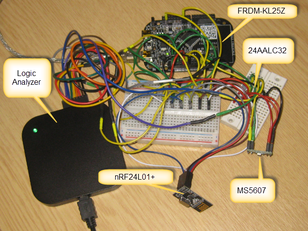
Bread Boarding the Data Logger System
Yes, the wiring in the picture looks messy, but it allows quick prototyping and inspection of signals with a logic analyzer.
💡 I get frequent questions and requests about “my SCI, SPI or I2C communication is not working!”: A logic analyzer or oscilloscope is something you should own. Without a logic analyzer, you likely will waste many, many hours. If you do not want to spend around $100 for professional tools, then I recommend you buy at least a $15 FRDM-KL25Z board and use it as a logic analyzer, see this post.
The system has following main parts:
- Microchip 24AA external I²C EEPROM to store data values and configuration data. Data is stored in the EEPROM until it is transmitted over the wireless transceiver.
- Nordic Semiconductor nRF24L01+ wireless transceiver for connectivity.
- MEAS MS5607 I²C digital absolute pressure sensor.
- ARM Cortex-M0+ processor on the FRDM-KL25Z.
I want to use a Cortex M0+ because of the low power characteristics of my application: The KL25Z is over-powered for my final design, but gives me a powerful development platform. And with using Processor Expert as hardware abstraction it allows me to change the processor later very easily: it will be just a different configuration made with a few mouse click :-).
The question is: how to use the FRDM-KL25Z to help with developing a battery operated low power embedded application?
My plan is the following:
- Breadboard setup of the system with the FRDM-KL25Z: this allows me to develop the software with all the needed hardware.
- Developing a simple ‘Arduino’ shield for the FRDM-KL25Z which has all the external parts (pressure sensor, EEPROM, transceiver) on it. This system will be battery operated and allows me to make long time measurement of the system.
- And finally to develop my board with another microprocessor on it (most likely a KL02 or KL05). In this stage I do not need the FRDM-KL25Z any more.
Low Power (not ‘Ultra-Low-Power’)
The final system will be battery operated, so I need to make sure it uses as few energy as possible. Or better: that it uses as few energy as reasonable possible. And this means that the system shall consume less than 1 mA in average. Yes, this is not one of these ‘ultra-low-power’ applications. Silicon vendors advertise ‘nano-ampere’ solutions, but for many applications they are never achievable: to me these benchmarks are not realistic, as they assume that the processor is alive maybe one second every day? But my system needs to continuously measure and communicate several days a day. So a 99.9% inactivity is not achievable.
Silicon vendors build in multiple low power modes into their microcontroller: unfortunately many modes are easily usable waking up from the ultra-low-power modes is like a power-on-reset: all your SRAM is gone, and the peripherals and pin states are gone too. Such ultra-low-power modes are cool for a ‘dumb’ application, but were hard to deal with a more complex system where for example an operating system is running. Just to set the stage :-).
There is a lot which can be done to cut the power consumption, without impacting the application functionality or usability. The wireless transceiver, pressure sensor and EEPROM do not have critical power consumption in my design. What is critical is the processor: I need to get it down to below 0.5 mA. And do not want to switch the processor completely off: it shall run the operating (FreeRTOS) RTOS all the time :-).
FRDM-KL25Z RevE
For my experiments, I’m using the RevE version of the FRDM-KL25Z board. Compared to the earlier RevD it has a newer silicon plus jumpers to disconnect better parts on the board to reduce the power consumption. And I’m using CodeWarrior for MCU10.5 with Processor Expert:
- Processor Expert makes it easier to deal with the low power modes: no need to spend many hours reading to silicon reference manual to understand all the different low power modes. And it makes it really easy to move to another processor later.
- CodeWarrior debugger nicely is able to debug low power modes. Unlike other debuggers, it keeps the connection with the target under debug even if the microcontroller is in low power modes.
Test Setup
To keep things simple in a first phase, I measure only the power consumed by the FRDM-KL25Z (and ignore the external sensors/etc).
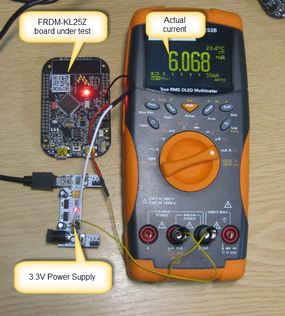
Test Setup
In my system I use a microcontroller voltage of 3.3V. Reducing the Vdd voltage usually has positive (square) impact. In my experiments I’m not going to reduce the Vdd. I instead focus on disabling unused board components, reducing clock speed and using low power modes.
The FRDM-KL25Z board runs a stripped down version of my application (just without the sensor and wireless application pats. I’m using a technique with ‘platform macros’ to enable/disable application functions:
#ifndef PLATFORM_H_ #define PLATFORM_H_ #define PL_BOARD_IS_FRDM 1 #define PL_HAS_LOW_POWER 1 #define PL_HAS_SHELL     0 #define PL_HAS_LED       1 #define PL_HAS_RTOS      0 #endif /* PLATFORM_H_ */Board Power Measurement Jumpers
The FRDM-KL25Z RevE board has two jumpers (J3 and J4) to measure the power used by the KL25Z and/or the power used by the K20 for the OpenSDA debug interface:
J3 and J4 on FRDM-KL25Z (Source: Freescale)
Both headers are not populated by default. J3 has a 0 Ohm and 10 Ohm resistor populated.
💡 I guess the idea is to remove the 0 Ohm (R73) so the voltage across R81 (10 Ohm) could be measured by the KL25Z itself?
On the RevD boards both headers hat a ‘cut trace’ between the jumper. I decided to remove all three resistors (R73, R81 and R74) so I can measure the current consumed.
R73 R81 and R74 removed
💡 Removing SMD components without the proper equipment is challenging! It works best with SMD de-soldering iron tips. The RevD approach with cutting traces was more user-friendly.
Starting Point: 19.58 mA
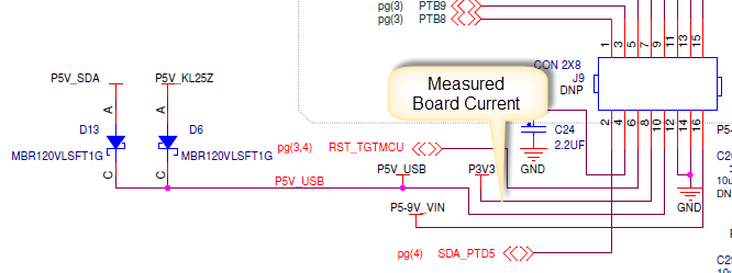
I’m not so much interested here about the current consumed by the KL25Z and K20 (OpenSDA), as I need to focus on the overall board consumption. For my experiments I measured the board current coming through the P3V3 on pin 8 of J9:
Measured Board Current (Schematic Source: Freescale)
I started my experiments with following starting point:


- KL25Z using 8 MHz external crystal (PEE mode, 48 CPU clock and 24 MHz bus clock)
- FreeRTOS running SysTick for with 100 Hz RTOS tick counter
- Shell command line interface through OpenSDA (38400 baud)
- Blinking LED heartbeat so I can see that the application is running properly
With this, the board consumes 19.58 mA:
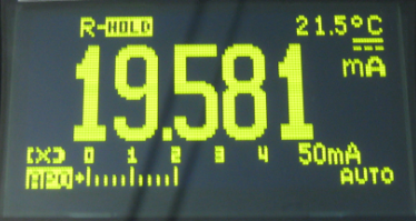
Base Board Current Consumption
Disabling Accelerometer: 19.55 mA
One rule of low power: disable what I do not use. The FRDM-KL25Z has the MM8451 accelerometer on the board, so I disabled it (disabled the accelerometer through the I²C interface/shell). But saving were minor. I guess only removing the accelerometer would bring some extra savings.
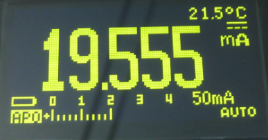
Accelerometer disabled
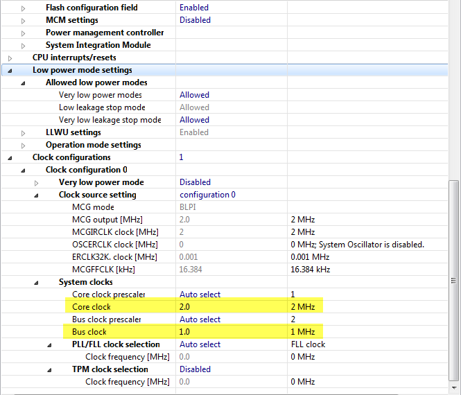
Reduced Clock Speed: 11.91 mA
Second rule of low power: slow down the clock speed. Current consumption usually is linear to the used clock speed. So reducing the clock speed should greatly reduce the current. I do not need that 48 MHz clock speed for my application. So I reduce the core clock to 2 MHz and the bus clock to 1 MHz:
- External Crystal 8 MHz
- MCG settings to BLPE (Bypass Low Power External reference clock)

BLPE with external Crystal
gives about 12 mA:

2 MHz with external clock
Disabled OpenSDA: 7.23 mA
I still have a lot of current consumed. And one part of this is the K20 microprocessor on the board used for OpenSDA. To get rid of that extra current:
- Disconnect P3V3_SDA (remove R74 and remove jumper on J3)
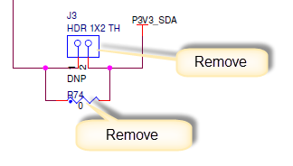
Removed Power to K20
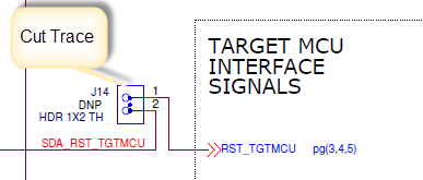
- Disconnect OpenSDA reset line: for this cut the trace under J14 and install a jumper

Cut J14 Trace
Remove the J14 jumper to disconnect the reset line between the KL25Z and K20 OpenSDA, as otherwise current can flow between the K20 and KL25Z:
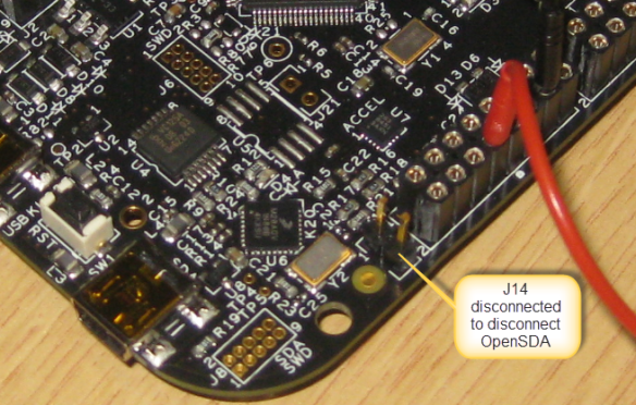
J14 disconnected by Jumper


With this, the current went down to 7.2 mA:
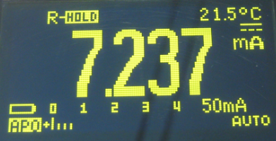
Disabled OpenSDA
Cut J20: 3.55 mA
Good progress so far: from 20 mA down to 7 mA. But what caused me a lot of head scratching: I would not have expected that 7 mA: it should be more in the 3-4 mA range. And indeed, measuring the current to the KL25Z microcontroller on J4 showed 3.4 mA:

KL25Z current at 2 MHz
So what is using all the excess current? My goal is to go below 1 mA, and somehow the board itself already uses 3.6 mA somewhere. It took me more head scratching (that’s why I’m getting bald ;-)). And after a while I realized that current must be flowing back into U1:
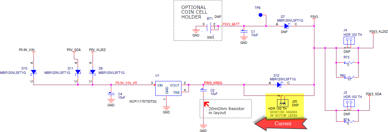
Current flowing back through J20
With this, I decided to the trace under J20 and to install a jumper there to prevent that current:
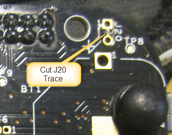
Cut J20 Trace
Now my board shows a current I expect :-):
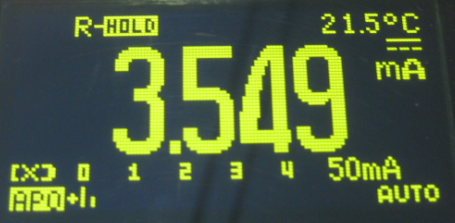
Current after cutting J20
Using Internal Clock: 2.69 mA
One general rule for low power is: using an external crystal uses less energy than using an internal (on chip) clock generator. However as the FRDM-KL25Z has a high frequency 8 MHz clock needed for its USB operation, it is probably better to use the internal (slower) clock generation module.
For this I disable the external crystal and change the mode from BLPE to BLPI (Bypass Low Power Internal):

Disabled Oscillator and BLPI mode
BLPI Settings
And the result is again a reduced current consumption:

Internal Clock
❓ I did not expect that much reduction. Not sure why it has such a big impact. But it seems that this 8 MHz external crystal really is not good for low power applications?
Very Low Power Mode: 2.08 mA
To enter the ‘Very Low Power Modes’, I enable the setting in the CPU component. But as the bus clock cannot exceed 800 kHz in this mode, I set it to the next closest value:

Very Low Power Mode Settings
With this, I’m close to 2 mA :-). But still twice as high as where I want to be :-(.
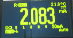
Very Low Power Enabled
Where is my current going?
To be clear: I’m down to 2.08 mA for the board, while the microprocessor is in RUN mode. So I not enter any of the special low power modes (yet). Still for 2 MHz CPU clock that 2.0 mA are too high to me?
So decided to do another measurement: measuring both the board current and the KL25Z current with the OpenSDA on the board enabled (J14 and P_SDA enabled).

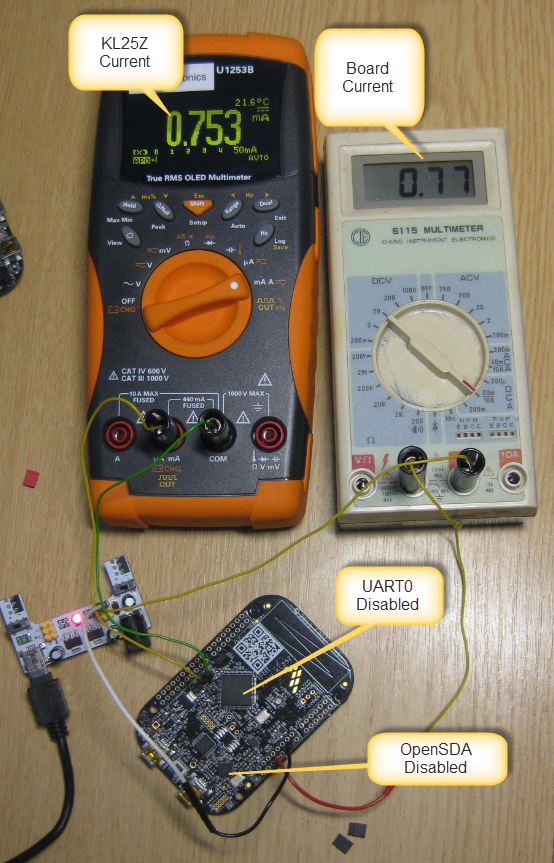
KL25Z and Board Current
That 6.65 mA for the board is no surprise: the K20 of the OpenSDA is active. However what is interesting to see is that the K25Z current is down to 0.754 mA with the OpenSDA active, while it is very close to the 2.083 mA if the OpenSDA is *not* active. This means that about 1.3 mA is going ‘somewhere’ from the KL25Z if the OpenSDA is deactivated. The question is: where, and why?
OpenSDA Serial Interface
I already have cut the reset line between OpenSDA and the KL25Z. But there is the OpenSDA Serial-to-USB CDC connection:
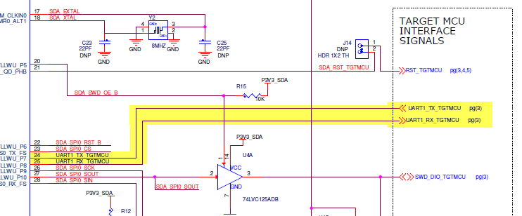
OpenSDA UART Connection
And I’m using a UART0 in my application: I’m using it to communicate through OpenSDA to the host machine. But now I have OpenSDA disconnected, and there could be a current flowing from the KL25Z to the K20 (which is unpowered). So I turned of the shell and UART, and look at this :-):
UART0 and OpenSDA disabled
I’m getting definitely better 🙂
Processor Expert Low Power Modes
So far I’m not using any low power modes. The cool thing with Processor Expert is, that it makes usage of low power modes really easy. Calling SetOperationMode() changes between the different low power modes:
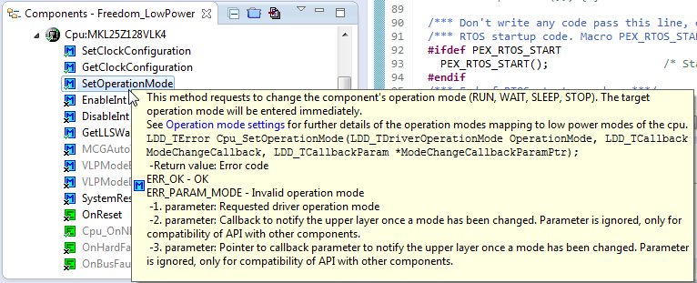
SetOperationMode
There are several settings inside the CPU component which deal with low power. First is the ‘Low power mode settings‘ group:

Low Power Mode Settings
In above dialog I specify which modes are allowed, and which interrupt/events bring me out of Low Leakage mode (LLWU = Low Leakage Wakeup Unit): Usually I use the Low Power Timer (LPTMR) to wake me up.
In the Operation mode settings I can specify
- Which mode shall be entered with SetOperationMode()
- What should happen after the wake-up interrupt
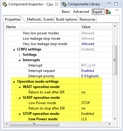
Operation Mode Settings
Entering Low Power Mode: WAIT down to 0.155 mA
With this, everything is ready to use low power modes from the application.
In my application I have a variable LP_mode:
typedef enum { LP_RUN, LP_WAIT, LP_SLEEP, LP_STOP } LP_PowerMode; static LP_PowerMode LP_mode;which is defining the current active low power mode. To switch into a low power mode I use SetOperationMode():
if (LP_mode==LP_WAIT) { Cpu_SetOperationMode(DOM_WAIT, NULL, NULL); /* next interrupt will wake us up */ } else if (LP_mode==LP_SLEEP) { Cpu_SetOperationMode(DOM_SLEEP, NULL, NULL); /* next interrupt will wake us up */ } else if (LP_mode==LP_STOP) { Cpu_SetOperationMode(DOM_STOP, NULL, NULL); /* next interrupt will wake us up */ } /* interrupt will wake us up, and we are back in RUN mode */WAIT is really easy to use: basically it stops the core clock, while interrupts are still active. And a perfect place to enter that low power mode is from the FreeRTOS Idle task hook:
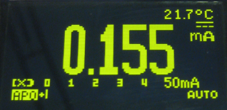
void FRTOS1_vApplicationIdleHook(void) { /* Called when the RTOS is idle (from the IDLE task). Here would be a good place to put the CPU into low power mode. */ LP_EnterLowPower(); }Just doing the WAIT mode I get down to 0.155 mA :-):
WAIT mode enabled
❗ With the above setup, I have only one task running and a blinking LED. The application with all the sensors will have two more tasks added, so the power consumption will go up again.
FreeRTOS Tickless Idle Mode: 0.132 mA
FreeRTOS comes with a cool low power feature: the Tickless Idle Mode. I have enabled it along with using the special Systick Prescaler:
FreeRTOS Tickless Idle Mode
With this, the RTOS will delay the SysTick interrupts as long as possible, extending the low power idle modes and reducing the interrupt load. And this is what I get as board current 🙂 :
WAIT with FreeRTOS Tickless Idle Mode
UPDATE: Down to 2 uA with FRDM-KL25Z Board RevE
I tried the same project with my FRDM-KL25Z Board RevE. Here I removed the resistors R73 and R81 to measure directly the current over J4. And finally, I reached 2 uA 🙂
2.11 uA with FreeRTOS on FRDM board
I had to change a few things:
- Disabled the serial/shell connection to the OpenSDA
- I had the external crystal enabled (but had not used it 😦 ). This alone was drawing a lot of current. Disabling System Oscillator 0 in the CPU setting helped a lot.
- Disabled the PLL module in STOP mode (as not used).
Summary
The week-end is over, and I need to stop here at the WAIT mode. I have not explored the more advanced SLEEP and STOP modes, but on the other hand I’m now well below my target of 1 mA for the board anyway
.
Modern microcontroller come with many advanced low power modes. Unfortunately for many applications most extreme low power modes are not usable as they completely shut down the processor, making it hard to use with an application e.g. using an operating system. The Freescale KL25Z processor is no exception to this. But even with ‘moderate’ power saving settings I’m able a reasonable power reduction. Still, there are a lot of settings, and I it is definitely not easy to find my way through the endless and complicated settings the silicon designers have invented. But at least with Processor Expert things are easier to find and configure.
Development boards are great for development or evaluation. They are usually not designed for low power usage, because they have too much components on it consuming energy. However, as shown with the FRDM-KL25Z it is possible to get into a working solution:
- Disable by software any external devices not used (e.g. Accelerometer)
- Disable any on-board debugging devices (e.g. OpenSDA). Do not only cut power, disable as well any other debugging signals (e.g. Reset).
- Carefully check the changed current flow if not using the on board regulators (e.g. prevent current flowing back to the regulators).
- Make sure that there is no current through connection lines to unused devices (e.g. UART0 to K20 OpenSDA).
- Using an RTOS like FreeRTOS does not mean it cannot use low power modes. A mode like WAIT already greatly reduces the power consumption. The tickless idle mode of FreeRTOS is helping to reduce the power consumption too.
- I would not have been able to reach this in such a short time without the help of Processor Expert 🙂
The project I have used for my testing is available on GitHub. Hope this is useful, and helps your battery powering a FRDM-KL25Z. So far I have reached my goals with a board consumption less than 1 mA :-). But as soon as I find time, I’ll explore the more advanced low power modes. Until then, have a look at the Freescale web site for any documenation about how to use the low power modes for the KL25Z (or any other ARM Cortex-M0+).
Happy Low-Powering 🙂


Great!
Maybe you will think of powering the board from a small solar cell and charging a small Li-Ion battery? This way the system will become autonomous.
This is why I switched from Microchip PICs to Freescale. I struggled about 1 year on a past project trying to obtain such power reduction.with no good results.
LikeLike
Hi Cristian,
yes, the plan is to have a small battery (potentially with a solar cell added to charge it). I would like to achieve at least 6 month of battery operation.
LikeLike
By the way, you have a nice multimeter!
LikeLike
Hi Cristian,
you mean the orange one? Yes, it is a really nice one, but I do not own it: I borrowed it from the university lab for my weekend work. I own the cheap one shown on one of the pictures: it is not as accurate and has not that many functions, but good enough for simple measurements.
LikeLiked by 1 person
Nice post and useful!
Before you did it, I tried the VLLS0 and I achieve a 0,242 mA. Future Challange: your 0,132 mA ^^
LikeLike
Did you measure this for the whole board or just for the microcontroller? As outlined in the post, there is a lot of current consumed by the board itself. The other things I noticed: forgetting to set a bit in the microcontroller has a big impact on the power consumption: this is where Processor Expert helped me a lot.
LikeLike
Hi Erich!
I don’t use the FRDM Board, I use my own one (is for a remote controller).
When I need to improve my project, I will read this post further for reduce the power consumption.
Keep doing this fantastic/useful work!
LikeLike
Erich
What batter y do you think of using? Will it be the coin-sized 3.3V type?
LikeLike
Initially it will use 3 AAA NiMH batteries. This gives me easily 3k-4k mAh. Weight/size is not much of a concern.
LikeLike
Will you get the full capacity out of NiMH cells over the span of 6 months? I would think they’d go dead sooner than that because of self discharge.
LikeLike
Yes, I have that concern too: I have not made measurements (yet), but I do not expect to get the full capacity.
LikeLike
What about the battery banks used for phones and mobile devices? They have their own charge system and come with capacities from 1200 mAh to 50000 mAh or more,,, I bought one of 12000 mAh and I’m thinking of using it in my final project for the institute… What do you think?
LikeLike
I would be careful using such battery packs if they do not come with the needed protection. If they have have their own charging, undervoltage and overvoltage protection, they might be safe to be used. NiMh cells are are safe compared to LiPo cells: You can easily burn down a house (or more) if not handling them properly! Things might be safe if they are under constant supervision. But even using normal battery charging systems might be dangerous if not constantly monitored or put into a fire-safe place.
LikeLike
Hello,
I really enjoyed this post, and many others.
To obtain a decent low power design, you really have to create your own board–too much stuff on the Freedom KL25Z leaking current. To that end, would you consider a post creating a bare minimum board from scratch?
Thanks,
John J. Flicker
LikeLike
Hi John,
yes, I 100% agree: for decent low power board it would require a re-design. Along with potentially lowering the supply voltage say to 2.8V or lower. If I create my next board from scratch, I’ll post something for sure.
LikeLike
Erich,
I modified this project to run on a FRDM-KL46Z board and it seems to work fine but I have found one unexpected thing inside the Cpu_OnLLSWakeUpINT() handler. For me, the Cpu_GetLLSWakeUpFlags() always returns 0. I tested this by putting a conditional LED toggle inside the ISR. This doesn’t seem to impact the operation but it is not the behavior I expected. I found a post freescale community about a similar issue using the RTC_Seconds LLWU interrupt. I’m curious, when using the KL25Z do you actually see the LPTMR flag being set?
Thanks!
Eric
LikeLike
Hi Eric,
yes, it has the LPTMR flag set for me using the FRDM-KL25Z.
Below is my code I’m using. Posted with https://mcuoneclipse.com/2014/03/16/starting-point-for-kinetis-low-power-lls-mode/
void Cpu_OnLLSWakeUpINT(void)

{

  APP_OnLLSWakeUpInterrupt();

}

void APP_OnLLSWakeUpInterrupt(void) {

  uint32_t tmp;
tmp = Cpu_GetLLSWakeUpFlags();
if (tmp&LLWU_INT_MODULE0) { /* LPTMR */
LPTMR_PDD_ClearInterruptFlag(LPTMR0_BASE_PTR); /* Clear interrupt flag */
}
}
I hope that helps. But I have not used that mode with the KL46Z, so it even could be a silicon problem.
LikeLike
Thanks for the reply, Erich. Here’s my code, adapted from your FreeRTOS version. I found that calling LED1_On inside your original “if” didn’t work, so I created another “if” just to see if any flags are set but they aren’t. If I move the LED1_On call outside of the “if” statements then the LED illuminates as expected so I know this function is being executed.
void Cpu_OnLLSWakeUpINT(void)
{
uint32_t tmp;
tmp = Cpu_GetLLSWakeUpFlags();
if (tmp&LLWU_INT_MODULE0) { /* LPTMR */
LED1_On(); /* red */
LPTMR_PDD_ClearInterruptFlag(LPTMR0_BASE_PTR); /* Clear interrupt flag */
}
if (tmp) {
LED1_On();
}
}
I’ll be happy to post my project if you want to try it out. In the mean time I’ll try the Freescale forums to see if they have an explanation.
LikeLike
Hi Erich,
Using this post as a starting point I was able to get down to 220uA.
Actually I disabled the low power clock modes and kept the processor running at 48MHz. And simply called Cpu_SetOperationMode(DOM_STOP, NULL, NULL) within FRTOS1_vApplicationIdleHook. I had FreeRTOS set to use Systick, and also enabled the low power timer in the FreeRTOS setup. Actually in my app, I’m using a UART for outputting status info, so in Idle I actually have to check if it’s still outputting characters, and do a DOM_WAIT if that’s the case rather than stop. For me, WAIT draws about 3mA, and STOP draws 220uA. Status is infrequent enough to not impact the overall power significantly. Give it a try!
LikeLike
Hi Erich,
The weirdest thing happened.. I’m using the same board and the same software version of CodeWarrior, but there is no Cpu_SetOperationMode function avaiable. Did you do a update or something like that to enable the Low Power Mode functions?
LikeLike
Hi Aline,
you are very likely in the ‘Basic’ view. Switch to the Expert/Advanced view, see https://mcuoneclipse.com/2013/01/27/enabling-the-expert-level-in-processor-expert/
I hope this solves your problem.
Erich
LikeLike
Hi Erich! I’m using a KL46Z for make a stand alone sensor with a battery, but the board consumption is 25mA, I’m using FreeRTOS and puting in the Application Idle Hook the WFI instruction, and works good downing the consumption to 22mA. But I’m trying put the MCG in FBI mode but the LCD display and the buttons don’t work. Do you know what I need configuring to work in FBI mode (or another with less consumption) for down the consumption and work with the display and buttons of the board. Thanks!
LikeLike
Hi Carlos,
WFI will not be enough: use it with tickless idle mode (see https://mcuoneclipse.com/2013/07/06/low-power-with-freertos-tickless-idle-mode/). Key is that you have no task activity as long as possible. Then use the low power timer (LPTMR) as outlined in https://mcuoneclipse.com/2014/02/09/iot-freertos-down-to-the-micro-amps/), but keep in mind that only some interrupt sources are able to wake up from the deep low power modes.
I hope this helps,
Erich
LikeLike
Hi Erich,
currently I am working on a project which involves both the KL25Z and the FRDM-FXS-MULTI sensor board.
The sensor board alone draws approx. 2mA of power (with an SD-Card present) and the KL25Z on its own if put into standby is <1mA. However both components together draw a whooping 10-11mA when running and about 9mA when put into standby.
Any ideas what I am doing wrong?
LikeLike
Hi Maximilian,
there are a lot of components on that board (many sensors), so are you sure all and every of them is in low power mode and does not draw extra current? Additionally, the FRDM board itself (as outlined in my article) is not that much low power too, because of the extra components. So I suggest you check your board and all the sensors, how much current they use?
LikeLike
Just re-meassured everything.
The only thing I noticed was a slightly increased power draw when the sd-card is writing (which is expected), but that does not happen when the board is put into standby.
Also one odd thing I noticed if I removed R24 on the Kl25Z the power consumption gets down to the expected level, but then I2C communication with the sensor board fails (apparently the SCL signal is pulled down then).
LikeLike
Hi, I have tried to follow the steps when I the resistors (R73, R81 and R74) and cut the trace for J3 to measure the current consumption of KL25 I encounter a problem. My code does not run as I know there should be a LED blinking. Power goes to MCU but nothing happens. If I put hat of J3 back and put power for the FRDM-KL25 everything is good and it is working. I want to put the power down and I need to measure current consumption of the MCU.
Thanks,
Bharat
LikeLike
Have you cut the J14 as well?
LikeLike
Hi,
How can I impliment
Cpu_SetOperationMode(DOM_STOP, NULL, NULL);
in online Mbed Compiler? Do you have any example? I do not have access to Eclipse and I want to load a low power mode code to my KL46Z.
Do you have any low power mode code in Mbed Compiler?
I tried just to put to deeplsleep(); but this does not make the system to be low power. I measured the consumption and it is 0.54 mA.
Thanks,
Xie
LikeLike
Hi Xie,
No, this is Processor Expert code and does not exist in mbed. I recommend you should use the MCUXPresso SDK instead, as this is easier to use than mbed and you have working drivers and examples with it.
I hope this helps,
Erich
LikeLike
Hi Erich,
I’m using FRDM-KL02z board and this board communicates with an external sensor using I2C, I’m measuring the current consumption of the KL02Z MCU from J4 it is 6.87mA. Do not know why it consumes this high current as it should be much less. I’have tried to disable the OpenSDA circuit supply by removing the jumper from J5 but the microcontroller stops communication with the sensor. Could you please give me advice on how to reduce the current?
Regards
Banu
LikeLiked by 2 people
Are you in deep sleep/low power mode with the KL02Z? If you are in running mode, then 6 mA are not that unusual.
LikeLiked by 2 people
Hi Erich,
Thank you for replying.
Yes, I tried the low power mode and the current consumption reduced from 8.4mA at running mode to 6.8mA at low power mode.
Are they any method to reduce the current consumption? like the demo, you explained above for FRDM-KL25z. I want to disable the open SDA circuit by removing the jumper but the microcontroller does not seem working when I do that. Could you please explain to me how to do that?
LikeLiked by 1 person
You can go down much more than 6.8 mA, but you have to use LLS mode for example (https://mcuoneclipse.com/2014/03/16/starting-point-for-kinetis-low-power-lls-mode/). To disable the OpenSDA circuit you have to not power the K20. Additionally you have to make sure you are not driving it with the Rx/Tx lines (OpenSDA UART connection to the KL25Z). Check your accelerometer: is it still running?
I hope this helps.
LikeLiked by 1 person
Hi Erich,
I did the following steps:
1- Removed the accelerometer.
2- Checked the Rx/Tx lines.
3- I don’t have P3V3_SDA but based on the KL02z schematic, I Disconnect P3V3_USBSER of FRDM-KL02z ( R28 removed but when I remove the jumper on J5 the MCU stops working, therefore, I kept the jumper), do you have any idea why?.
4- Changed the MCG mode to BLPI and core and bus clock to 2MHz as I could not go lower because of the I2C bus speed 100KHz.
The MCU current consumption reduced to 1.5mA please notify me if I did something wrong in my steps. Do you have any other suggestions for reducing the current exclude the LLS mode?
LikeLike
3) I’m not sure why removing P3V3_USBSER has that impact. That part of the schematics is different from other boards, but it seems indeed to be the voltage rail to supply the accelerometer and the OpenSDA circuit.
4) Other suggestion would be to check if there any other peripherals on your device still clocked, but you don’t need them. For example if you have a UART and you don’t use it, make sure it is not provided with a clock (turn off the clock gate).
I hope this helps.
LikeLiked by 1 person
Hi Eric,
I have a FRDM-K25Z board, with the 8MHz crystal replaced by 32768 Hz. I followed your instructions, except for disabling the accelerometer. No peripherals are enabled, except for some GPIO ports.
I have a simple SDK 2 program which basically just sits there in VLPS mode:
BOARD_InitBootPins();
BOARD_InitBootClocks();
BOARD_InitBootPeripherals();
SMC_SetPowerModeProtection(SMC, kSMC_AllowPowerModeVlp);
SMC_PreEnterStopModes();
SMC_SetPowerModeVlps(SMC);
SMC_PostExitStopModes();
It is definitely stuck there, however the power (measured on the P3V3_KL25Z jumper) is 2mA, and is also dependent on the clock frequency (2MHz in this case). So, the clock is apparently running for some reason? This is also independent on whether the debugger USB is connected or not (all relevant jumpers are disconnected).
Do you have an idea whet may be happening?
Thanks,
Eyal Doron
LikeLike
Hi Eyal,
I suspect that you still have clocking enabled in InitBootClocks()?
Best if you could compare the code with Processor Expert settings, as Processor Expert is dealing with low power settings in a smart way.
LikeLike
Dear Erich,
Thanks for your MCU on Eclipse, which is a great webpage to have guidelines about the Kinetis microcontrollers!
I have been testing the VLPR of the KL03, and there is something very strange that I would like to discuss:
If I evaluate my code with the FRDM-KL03 REVB2, the current consumption of my microcontroller after setting the VLPR mode is 318 µA (measured at the J10 jumper, and removing both the R32 and R27 resistors). However, if I do this measurement in a KL03 microcontroller (also QFN package) that has been programmed with the same code, and connected to a 3.3 V source, I have a current consumption of 1.4 mA while running in VLPR.
Is it possible that the FRDM board and its J10 is not giving me the real current consumption of the device? I would have expected that the FRDM measurement would be higher because of the debugging system, but this is not the case and the difference is huge. I am concerned about the current consumption of the bare microcontroller. The FRDM measurement is very similar to that stated in the KL03 datasheet.
To have in mind about the code:
LIRC is the main clock, running at 8 MHz.
Core/system clock = 4 MHz
Bus and flash = 1 MHz
Peripherals enabled: ADC, LPTMR, LPUART, TPM, PORTB
Have you ever seen this in your projects? Any idea would be greatly appreciated 🙂
LikeLike
Hi Andy,
What is different on your custom board? It could be that your microntroller has some floating pins or driving unwanted peripherals (I2C or UART can do this if they are not pulled down to GND).
Other than that, I have seen devices/microcontrollers damaged by ESD which can cause higher than usual power consumption: the device still ‘works’ but drains power internally. So it this just with one microcontroller or do you see this on others too?
I hope this helps,
Erich
LikeLike
Dear Erich,
The custom board does have floating pins (unconnected), however I forgot to configure all of them in the disabled state in MUX to avoid unwanted leakage. Thanks also for your comment about ESD, I will be more careful than ever with this issue. Once again, thanks for your reply!!!
LikeLiked by 1 person