Bootloaders are a very useful thing: it allows programming an application file without a debugger. This makes it ideal for upgrading a system in the field.
Usually, there are application notes and examples from silicon vendors available. But typically they are for a certain microcontroller, and hard to change it to another system without a lot knowledge about its implementation. What I need for a project based on the FRDM-KL25Z is a bootloader which shall be small and portable. As I’m using Processor Expert to keep my applications portable across different microcontroller families: why not create a bootloader with Processor Expert components? With the Processor Expert drivers available, things can get a lot simpler compared to the ‘traditional’ approach. With less than 10 KByte footprint?

Serial Bootloader made with Processor Expert
A bootloader is a program which is able to load another program (the application program). Typically the bootloader program is not changed, and is kept in the microcontroller. That way the bootloader can load again and again a different program.
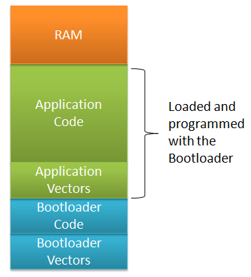
Bootloader and Application Memory Map
💡 Architecturally there can be a ‘mini’ or ‘micro’ bootloader which can load the ‘real’ bootloader. E.g. the OpenSDA bootloader on the Freedom boards have this capability.
The Bootloader Code and the Bootloader Vectors are programmed into a new part (e.g. with a debugger or a standalone flash programmer (e.g. with USBDM). Then the Bootloader can be used to load or change the Application Code and Application Vectors. With this, the Bootloader remains the same, while the Application can be updated.
Bootloader Sequence
A typical bootloader is doing something like this
- The bootloader decides at startup if it should enter bootloader mode or if it shall run the application. Typically this is decided with a button or jumper set (or removed). If it shall run the application, the bootloader calls the application and we are done :-).
- Otherwise, the bootloader will reprogram the application with a new file. S19 (S-Record) files are often used for this, as they are easy to parse and every tool chain can produce them.
- The bootloader needs to use a communication channel to read that file. That can be RS-232, USB or an SD card file system (e.g. FatFS).
- Using that file, the bootloader programs the flash memory. Special consideration has to be taken into account for the application vector table. As the bootloader runs out of reset, it is using its own (default) vector table, and needs to relocate the vector table if running the application.
💡 It would be possible to use the reset button on the FRDM-KL25Z board as a user button (see this post). To keep things simple, I’m using a dedicated bootloader push button on PTB8.
So writing a bootloader requires the following parts:

Bootloader System Block Diagram
- Communication Channel: File I/O or any other means to read the Application File.
- File Reader: A reader which reads the Application File.
- Flash Programming: to program the Application.
- Vector Redirection: To switch between the Bootloader and Application Vector Table.
- User Interface: Showing status and information to the user, and to switch between application and bootloader mode at system startup.
Processor Expert comes with Flash Programming and Communication components (USB, SCI, I2C, …) installed. I have a Shell user interface already, plus an S19 file reader component created. Combining this with my other components should enable me to make a bootloader :-).
Flash Memory of the Bootloader
To make sure the bootloader gets linked only into its space, I reduce the FLASH memory for it. With the settings below I limit the FLASH memory from 0x0000 (vector table) up to 0x3FFF. That means my application memory area starts at 0x4000.
So I change the available flash for the bootloader in the CPU properties, and cut the available FLASH size on the KL25Z128 from 0x1FBF0 (~128 KByte) in the Build Options tab to 0x3FB0:
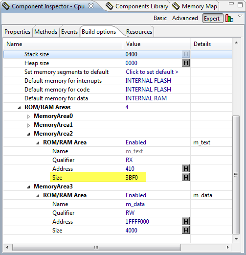
Bootloader FLASH Area
With this, the bootloader occupies the space from address 0x0000 (vector table) up to 0x3FFF.
Flash Protection
My bootloader resides in the first lower flash pages. To avoid that it might get destroyed and overwritten by the application, I protect the bootloader flash blocks. There is a setting in the CPU component properties where I can protect 4 KByte regions:

Protecting Regions in the CPU Component
Terminal Program
For my bootloader I need a way to send a file with a terminal program. As my serial connection has only Tx and Rx, but no RTS/CTC lines for flow control, it is useful if the terminal program either implements software flow control (XON/XOFF), or a delay value for sending a file.
After some searching the internet, I have found an open source terminal program which exactly can do this: https://sites.google.com/site/terminalbpp/

Terminal Program
It supports sending a file with a delay (shown above with 1 ms delay), and supports XON and XOFF. I used it successfully with my bootloader.
💡 Using a zero delay did not work in all cases. Not yet sure why. What worked was sending a file with a 1 ms delay setting.
Bootloader Shell
The bootloader features a shell with following commands:
--------------------------------------------------------------
FRDM Shell Bootloader
--------------------------------------------------------------
CLS1                      ; Group of CLS1 commands
  help|status             ; Print help or status information
BL                        ; Group of Bootloader commands
  help|status             ; Print help or status information
  erase                   ; Erase application flash blocks
  restart                 ; Restart application with jump to reset vector
  load s19                ; Load S19 file
The ‘BL status’ command shows the application flash range, and the content of the application vector table (more about this later):
  App Flash  : 0x00004000..0x0001FFFF
  @0x00004000: 0xFFFFFFFF 0xFFFFFFFF
With ‘BL restart’ it starts the user application (if any), and with ‘BL erase’ the application flash can be erased:
CMD> Erasing application flash blocks...done!
Bootloading an Application
With ‘BL load s19’ a new application file can be loaded. It will first erase the application flash blocks, and then waits for the S19. To send the file, I use the ‘Send File’ button:
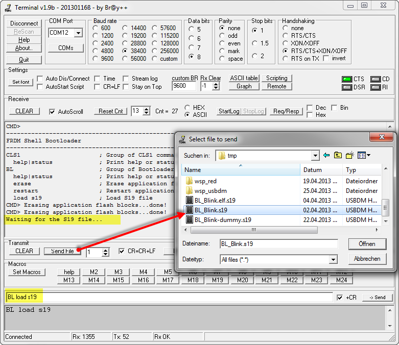
Loading S19 File
It writes then the address of each S19 line programmed to the shell console:
CMD> Erasing application flash blocks...done!
Waiting for the S19 file...
S0 address 0x00000000
S1 address 0x00008000
S1 address 0x00008010
...
S1 address 0x00009420
S1 address 0x00009430
S1 address 0x00009440
S9 address 0x00009025
done!
CMD>
Bootloader Details
If I enter ‘BL Load S19’, it executes the function BL_LoadS19() in Bootloader.c:
static uint8_t BL_LoadS19(CLS1_ConstStdIOType *io) {
  unsigned char buf[16];
  uint8_t res = ERR_OK;

  /* first, erase flash */
  if (BL_EraseAppFlash(io)!=ERR_OK) {
    return ERR_FAILED;
  }

  /* load S19 file */
  CLS1_SendStr((unsigned char*)"Waiting for the S19 file...", io->stdOut);
  parserInfo.GetCharIterator = GetChar;
  parserInfo.voidP = (void*)io;
  parserInfo.S19Flash = BL_onS19Flash;
  parserInfo.status = S19_FILE_STATUS_NOT_STARTED;
  parserInfo.currType = 0;
  parserInfo.currAddress = 0;
  parserInfo.codeSize = 0;
  parserInfo.codeBuf = codeBuf;
  parserInfo.codeBufSize = sizeof(codeBuf);
  while (AS1_GetCharsInRxBuf()>0) { /* clear any pending characters in rx buffer */
    AS1_ClearRxBuf();
    WAIT1_Waitms(100);
  }
  do {
    if (S19_ParseLine(&parserInfo)!=ERR_OK) {
      CLS1_SendStr((unsigned char*)"ERROR!\r\nFailed at address 0x", io->stdErr);
      buf[0] = '\0';
      UTIL1_strcatNum32Hex(buf, sizeof(buf), parserInfo.currAddress);
      CLS1_SendStr(buf, io->stdErr);
      CLS1_SendStr((unsigned char*)"\r\n", io->stdErr);
      res = ERR_FAILED;
      break;
    } else {
      CLS1_SendStr((unsigned char*)"\r\nS", io->stdOut);
      buf[0] = parserInfo.currType;
      buf[1] = '\0';
      CLS1_SendStr(buf, io->stdOut);
      CLS1_SendStr((unsigned char*)" address 0x", io->stdOut);
      buf[0] = '\0';
      UTIL1_strcatNum32Hex(buf, sizeof(buf), parserInfo.currAddress);
      CLS1_SendStr(buf, io->stdOut);
    }
    if (parserInfo.currType=='7' || parserInfo.currType=='8' || parserInfo.currType=='9') {
      /* end of records */
      break;
    }
  } while (1);
  if (res==ERR_OK) {
    CLS1_SendStr((unsigned char*)"\r\ndone!\r\n", io->stdOut);
  } else {
    while (AS1_GetCharsInRxBuf()>0) {/* clear buffer */
      AS1_ClearRxBuf();
      WAIT1_Waitms(100);
    }
    CLS1_SendStr((unsigned char*)"\r\nfailed!\r\n", io->stdOut);
    /* erase flash again to be sure we do not have illegal application image */
    if (BL_EraseAppFlash(io)!=ERR_OK) {
      res = ERR_FAILED;
    }
  }
  return res;
}
It first fills a callback structure of type S19_ParserStruct:
typedef struct S19_ParserStruct {
  uint8_t (*GetCharIterator)(uint8_t*, void*); /* character stream iterator */
  void *voidP; /* void pointer passed to iterator function */
  uint8_t (*S19Flash)(struct S19_ParserStruct*); /* called for each S19 line to be flashed */
  /* the following fields will be used by the iterator */
  S19_FileStatus status; /* current status of the parser */
  uint8_t currType; /* current S19 record, e.g. 1 for S1 */
  uint32_t currAddress; /* current code address of S19 record */
  uint16_t codeSize; /* size of code in bytes in code buffer */
  uint8_t *codeBuf; /* code bufffer */
  uint16_t codeBufSize; /* total size of code buffer, in bytes */
} S19_ParserStruct;
That structure contains a callbacks to read from the input stream:
static uint8_t GetChar(uint8_t *data, void *q) {
  CLS1_ConstStdIOType *io;

  io = (CLS1_ConstStdIOType*)q;
  if (!io->keyPressed()) {
#if USE_XON_XOFF
    SendXONOFF(io, XON);
#endif
    while(!io->keyPressed()) {
      /* wait until there is something in the input buffer */
    }
#if USE_XON_XOFF
    SendXONOFF(io, XOFF);
#endif
  }
  io->stdIn(data); /* read character */
  if (*data=='\0') { /* end of input? */
    return ERR_RXEMPTY;
  }
  return ERR_OK;
}
Parsing of the S19 file is done in S19_ParesLine() which is implemented in a Processor Expert component which I already used for another bootloader project:

S19 Parser
This parser is calling my callback BL_onS19Flash() for every S19 line:
static uint8_t BL_onS19Flash(S19_ParserStruct *info) {
  uint8_t res = ERR_OK;

  switch (info->currType) {
    case '1':
    case '2':
    case '3':
      if (!BL_ValidAppAddress(info->currAddress)) {
        info->status = S19_FILE_INVALID_ADDRESS;
        res = ERR_FAILED;
      } else {
        /* Write buffered data to Flash */
        if (BL_Flash_Prog(info->currAddress, info->codeBuf, info->codeSize) != ERR_OK) {
          info->status = S19_FILE_FLASH_FAILED;
          res = ERR_FAILED;
        }
      }
      break;
    case '7':
    case '8':
    case '9': /* S7, S8 or S9 mark the end of the block/s-record file */
      break;
    case '0':
    case '4':
    case '5':
    case '6':
    default:
      break;
  } /* switch */
  return res;
}
Of interest are the S1, S2 and S3 records as they contain the code. With BL_ValidAppAddress() it checks if the address is within the application FLASH memory range:
/*!
* \brief Determines if the address is a valid address for the application (outside the bootloader)
* \param addr Address to check
* \return TRUE if an application memory address, FALSE otherwise
*/
static bool BL_ValidAppAddress(dword addr) {
return ((addr>=MIN_APP_FLASH_ADDRESS) && (addr<=MAX_APP_FLASH_ADDRESS)); /* must be in application space */
}
If things are ok, it flashes the memory block:
/*!
* \brief Performs flash programming
* \param flash_addr Destination address for programming.
* \param data_addr Pointer to data.
* \param nofDataBytes Number of data bytes.
* \return ERR_OK if everything was ok, ERR_FAILED otherwise.
*/
static byte BL_Flash_Prog(dword flash_addr, uint8_t *data_addr, uint16_t nofDataBytes) {
  /* only flash into application space. Everything else will be ignored */
  if(BL_ValidAppAddress(flash_addr)) {
    if (IFsh1_SetBlockFlash((IFsh1_TDataAddress)data_addr, flash_addr, nofDataBytes) != ERR_OK) {
      return ERR_FAILED; /* flash programming failed */
    }
  }
  return ERR_OK;
}
The Flash Programming itself is performed by the IntFLASH Processor Expert components:
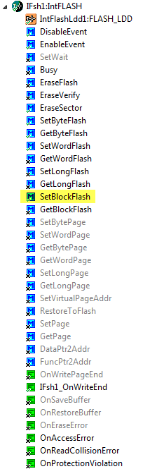
Processor Expert Flash Programming Component
This component is used for erasing too:
/*!
 * \brief Erases all unprotected pages of flash
 * \return ERR_OK if everything is ok; ERR_FAILED otherwise
 */
static byte BL_EraseApplicationFlash(void) {
  dword addr;

  /* erase application flash pages */
  for(addr=MIN_APP_FLASH_ADDRESS;addr<=MAX_APP_FLASH_ADDRESS;addr+=FLASH_PAGE_SIZE) {
    if(IFsh1_EraseSector(addr) != ERR_OK) { /* Error Erasing Flash */
      return ERR_FAILED;
    }
  }
  return ERR_OK;
}
Bootloader or Not, that’s the Question
One important piece is still missing: the bootloader needs to decide at startup if it shall run the Bootloader or the application. For this we need to have a decision criteria, which is typically a jumper or a push button to be pressed at power up to enter bootloader mode.
In this bootloader this is performed by BL_CheckForUserApp():
/*!
 * \brief This method is called during startup! It decides if we enter bootloader mode or if we run the application.
 */
void BL_CheckForUserApp(void) {
  uint32_t startup; /* assuming 32bit function pointers */

  startup = ((uint32_t*)APP_FLASH_VECTOR_START)[1]; /* this is the reset vector (__startup function) */
  if (startup!=-1 && !BL_CheckBootloaderMode()) { /* we do have a valid application vector? -1/0xfffffff would mean flash erased */
    ((void(*)(void))startup)(); /* Jump to application startup code */
  }
}
The function checks if the ‘startup’ function in the vector table (index 1) is valid or not. If the application flash has been erased, it will read -1 (or 0xffffffff). So if we have an application present and the user does not want to run the bootloader, we jump to the application startup.
Below is the code to decide if the user is pressing the button to enter the startup code:
static bool BL_CheckBootloaderMode(void) {
  /* let's check if the user presses the BTLD switch. Need to configure the pin first */
  /* PTB8 as input */
  /* clock all port pins */
  SIM_SCGC5   |= SIM_SCGC5_PORTA_MASK |
             SIM_SCGC5_PORTB_MASK |
             SIM_SCGC5_PORTC_MASK |
             SIM_SCGC5_PORTD_MASK |
             SIM_SCGC5_PORTE_MASK;
  /* Configure pin as input */
  (void)BitIoLdd3_Init(NULL); /* initialize the port pin */
  if (!BL_SW_GetVal()) { /* button pressed (has pull-up!) */
    WAIT1_Waitms(50); /* wait to debounce */
    if (!BL_SW_GetVal()) { /* still pressed */
      return TRUE; /* go into bootloader mode */
    }
  }
  /* BTLD switch not pressed, and we have a valid user application vector */
  return FALSE; /* do not enter bootloader mode */
}
I’m using BitIOLdd3_Init() to initialize my port pin, which is part of the BitIO component for the push button:
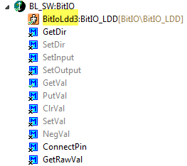
BitIOLdd Component
💡 When creating a BitIO component for Kinetis, Processor Expert automatically creates a BitIO_LDD component for it. As I do not have control over the name of that BitIO_LDD, I need to use in my bootloader whatever Processor Expert has assigned as name.
I’m using PTB8 of the Freedom board, and have it connected to a break-out board (pull-up to 3.3V if button is not pressed, GND if button is pressed):

FRDM-KL25Z with Bootloader Switch Board
You might wonder why I have to initialize it, as this is usually done automatically by PE_low_level_init() in main()? The reasons is: I need to do this *before* main() gets called, very early in the startup() code. And that’s the reason as well why I need to set the SIM_SCGC5 register on Kinetis to clock the peripheral.
Inside the CPU component properties, there is a Build option setting where I can add my own code to be inserted as part of the system startup:

User Code before PE initialization
To make sure it has the proper declaration, I add the header file too:

User data declarations
These code snippets get added to the __init_hardware() function which is called from the bootloader startup code:

Custom startup code with Bootloader code inserted
This completes the Bootloader itself. Next topic: what to do in the application to be loaded…
Application Memory Map
As shown above: the bootloader is sitting in a part of the memory which is not available by the application. So I need to make sure that application does not overlap with the FLASH area of the bootloader. My bootloader starts at address 0x0000 and ends at 0x3FFF:

Bootloader Memory Map
While the application can be above 0x4000. These numbers are used in Bootloader.c:
/* application flash area */
#define MIN_APP_FLASH_ADDRESS        0x4000  /* start of application flash area */
#define MAX_APP_FLASH_ADDRESS       0x1FFFF  /* end of application flash */

#define APP_FLASH_VECTOR_START      0x4000  /* application vector table in flash */
#define APP_FLASH_VECTOR_SIZE       0xc0    /* size of vector table */
The application just needs to stay outside the FLASH used by the bootloader:

Application Memory Map
To make this happen, I need to change the addresses for m_interrupts and m_text in the CPU build options:

Application Memory Area Settings
That’s it 🙂
💡 As for the ARM Cortex-M4/0+ do not need to copy the vector table in the bootloader to a different location, I can debug the application easily without the bootloader.
S-Record (S19) Application File Generation
The bootloader loads S19 or S-Records. This post explains how to create S19 files for Kinetis and GNU gcc.
Code Size
The bootloader is compiled with gcc for the FRDM-KL25Z board. Without optimization (-O0), it needs 13 KByte of FLASH. But optimized for size, it needs only 8 KByte 🙂 :
text       data        bss        dec        hex    filename
8024         24       2396      10444       28cc    FRDM_Bootloader.elf
Summary
With this, I have a simple serial bootloader for only 8 KByte of code. The bootloader project and sources are are available on GitHub here.
And I have several ideas for extensions:
- Using a memory stick to load the appliation file (USB MSD Host).
- Using a SD-Card interface with FatFS.
- Using a USB MSD device to load the file.
- Performing vector auto-relocation: the bootloader should detect the vector table at address 0x00 of the application file and automatically relocate it to another location in FLASH. That way I can debug the Application without change of the vector table.
- Making sure it runs on other boards and microcontroller families.
- Creating a special component for the bootloader.
While the bootloader only needs 8 KByte for now, I keep the reserved range at 16 KByte, just to have room for future extensions.
Happy Bootloading 🙂

Thank you for sharing this, Erich. I will almost certainly be adapting this for use in an SD card-based and eventually an over-the-air (WiFi) bootloader. Hopefully, I can contribute something back to your examples section on Github if I am successful.
Your blog has been my textbook for the past few weeks and will probably continue to be that in the near future.
LikeLike
Why can’t I find S19 in my processor expert components? (Also, Shell, Utility…)
LikeLike
Hi Liz,
you need to load the additional Processor Expert components first. See https://mcuoneclipse.com/2013/05/09/processor-expert-component-peupd-files-on-github/
LikeLike
Thank you!
LikeLike
I must update… okay I see. Sorry!! 🙂
LikeLike
Hey Erich,
I don’t have a switch board available, do you have any ideas how to avoid using one? Is using the TSI component of KL25z practical?
Thanks, Liz
LikeLike
Hi Liz,
you could consider to use the reset button:
LikeLike
Thank you! I have the bootloader somewhat working but I think I’m having trouble with the application part. I basically just made a copy of the FRDM_Bootloader project you provided and changed the Memory Areas like you showed in your tutorial above (for applications). I have the .s19 file being created but when I send it to the FRDM_Bootloader project through serial, I keep getting errors saying “Failed or unknown command” as it goes through the whole .s19 file.
Is there something I’m missing? Is the application code not supposed to have bootloader files on it?
Thank you,
Liz
LikeLike
Hi Liz,
are you using “BL load s19” as command?
LikeLike
Yes I am. I used “BL load s19” it erases and waits for the s19… then I send the s19 file.
LikeLike
I know that sending the S19 file is the most critical part. Are you sure you use an S19 file? Which program do you use to send the file? Can you post what you get after ‘waiting for the S19 file…’?
LikeLike
This is what I see while sending the s19 file…
Erasing application flash blocks…done!
Waiting for the S19 file…
S0 address 0x00000000ERROR!
Failed at address 0x00000400
failed!
Erasing application flash blocks…done!
*** Failed or unknown command: BL load s19
*** Type help to get a list of available commands
CMD> *** Failed or unknown command: S11340000030002035650000B151000
*** Type help to get a list of available commands
CMD> *** Failed or unknown command: 0BD510000B2
*** Type help to get a list of available commands
CMD> *** Failed or unknown command: S1134010BD510000BD510000BD51000
*** Type help to get a list of available commands
CMD> *** Failed or unknown command: 0BD51000064
… and it goes on and on with the failed or unknown commands, I’m guessing it goes through the whole s19 file.
I used https://mcuoneclipse.com/2012/09/13/s-record-generation-with-gcc-for-armkinetis/ to make my project generate a s19 file, I was originally getting hex files but then I read in the comments to that tutorial that you can change the suffix.
I use the terminal you recommended here to send the s19 file.
Thanks,
Liz
LikeLike
Can you try to increase the delay (the dialog next to ‘send file’)?
LikeLike
No success increasing the delay… is there an project of an application I can try using instead of using my own? Thank you.
LikeLike
I have sent you an S19 file I used by email.
LikeLike
Hi Erich,
I also meet the same issue. S19 file can not load correctly.
Can you send me you S19 file?
LikeLike
https://github.com/ErichStyger/mcuoneclipse
It’s in the BL_Blink project.
LikeLike
Thanks Erich, it worked
LikeLike
Hi Erich,
I’m having exactly the same problem as Liz below. I’ve tracked the parse error down to the second line in my S19 file, which uses the address 0x0400:
1: S01100004D4B32305F426C696E6B2E7331399A
2: S1130400FFFFFFFFFFFFFFFFFFFFFFFF7EFFFFFF79
3: S113400000000020CD480000694400008544000001
4: S11340108544000085440000854400008544000078
…
It looks like that line is related to the Flash memory configuration which resides at 0x0400, and I don’t quite know what to do about it or how you worked around that. Here is the corresponding section in my linker script:
MEMORY {
m_interrupts (RX) : ORIGIN = 0x00004000, LENGTH = 0x000001C0
m_text (RX) : ORIGIN = 0x000041C0, LENGTH = 0x0001BE40
m_data (RW) : ORIGIN = 0x1FFFE000, LENGTH = 0x00002000
m_data_20000000 (RW) : ORIGIN = 0x20000000, LENGTH = 0x00002000
m_cfmprotrom (RX) : ORIGIN = 0x00000400, LENGTH = 0x00000010
}
I’m going to try removing that line and sending the S19 file again, but please let me know if you have any better ideas.
Thanks!
Vishal
LikeLike
Hi Vishal,
I have committed my example project on GitHub. The important thing is that hte memory map is correct. See as well how the burner.bbl file is used in that project:
https://github.com/ErichStyger/mcuoneclipse/tree/master/Examples
LikeLike
Thanks, Erich! That was very helpful. Turns out, I had the Flash configuration field enabled in the CPU component, which was generating that S19 record.
LikeLike
I am working my way up to a Wifi-based firmware update procedure, as I mentioned in an earlier comment. The bootloader is basically working at this point, but I am having an issue with the button debouncing wait inside of BL_CheckBootloaderMode:
WAIT1_Waitms(50); /* wait to debounce */
After entering this code, the program seems to run some of the wait_cycles code a few times before resetting. I’m not sure why this happens, but I am using the FRDM K2050M, and I’ve made this project from scratch so there could be some tiny difference between my PE component setup and your FRDM KL25Z project that is messing with the flow. I can’t imagine what, since the WAIT component doesn’t require any initialization, and all the functions do is wait. Perhaps there is some incompatible assembly code in the lowese-level wait-cycle routines?
LikeLike
The Waitms(50) is simply to wait for some time in order to debounce the push button. As bouncing depends on the button, 50 ms might not be enough (I have seen buttons bouncing for as much as 200 ms). The other thing is that in earlier versions of the Wait component, the timing was not always correct. The new component on the GitHub has the fix (I’m using “Version : Component 01.059”, you can get that information from the WAIT1.c file. In any case, if this should be the problem, simply increase the waiting time to say 500 ms and let me know if this helps.
LikeLike
Sorry to keep bugging about this bootloader… I’ve been having a problem where the application will not run after successfully loading the s19 file and then restarting or running the program again without pressing down the button that loads the bootloader.
For example:
1. Press button and run project. “BL load s19” and send the s19 file.
2. Stop the debugging process.
3. Debug program again without pressing down button that loads bootloader.
4. EITHER a. Bootloader will run again (red light blinking). OR b. I get this error: No source available for “0xFFFFFFFE (0xFFFFFFFE)() ”
As I stepped through, the condition that doesn’t allow the application to run is when the BL_CheckBootloaderMode() returns FALSE to the if statement in CheckForUserApp(), the FALSE ends up being a “ÿ” which won’t allow the if statement to be completely true. I hope that’s clear.
I tried also using the reset button as well as soldering wires and using test leads as a “button press” similar to this tutorial but I keep getting this error. I haven’t changed anything from the projects you posted on GitHub, either.
LikeLike
Hi Liz,
>>3. Debug program again without pressing down button that loads bootloader.
Keep in mind that depending on how you debug, this will erase the whole flash, so only the bootloader will present on the target.
If that ‘No source available’ shows up, then this means that the debugger initial PC is set at this address where is no code, or that the ‘application code detection’ somehow failed to properly detect the application mode.
That “ÿ” is probably a debugger display problem, as it tries to show the value as character. Could you check the value in hex mode?
And: are you modified my unchanged example code, or your own one?
LikeLike
I did not modify your example code.
I made a bool variable, checkMode, to see what BL_CheckBootloaderMode() returns, it shows “checkMode = ÿ”, when I hover over the variable in the code. But, when I go into the “Variables” tab I see just a space like so, ‘ ‘ , with the single apostrophes. I made a uint32_t variable and set checkMode to it and in the “Variables” tab, the uint32_t variable reads 0. Stepping through, BL_CheckBootloaderMode() is for sure returning FALSE.
The “Variables” tab is where to see the hex value, correct?
LikeLike
Yes, you can use the variables view for this. To change the variable format right click on it and select Format > Hexadecimal.
See as well https://mcuoneclipse.com/2012/10/01/debugging-variables-in-hexadecimal-with-eclipse/
LikeLike
It shows that checkMode in hex is 0x00, and startup is not equal to -1, so I have no clue why the if statement isn’t allowing me in.
LikeLike
Hi Liz,
The code in BL_CheckBootloaderMode() is the following:
if (!BL_SW_GetVal()) { /* button pressed (has pull-up!) */
WAIT1_Waitms(50); /* wait to debounce */
if (!BL_SW_GetVal()) { /* still pressed */
return TRUE; /* go into bootloader mode */
}
}
/* BTLD switch not pressed, and we have a valid user application vector */
return FALSE; /* do not enter bootloader mode */
The logic is the following: if the button is pressend, then the pin returns 0 (FALSE). So pushing the button means that it gets a low voltage. If the button is not pressed, it shall be HIGH (logic high level). Typically this means that a normal button needs to have a pull-up resistor (either internally or externally). Do you have this? The button (BL_SW) shall not be floating. It needs to be either LOW if pressed, and high if not pressed.
LikeLike
Erich,
I have GND and PTB8 connected and working as a button press and P3V3 with a resistor and PTB8 connected when I want no button pressed (not working).
I feel like I want to give you more information… but I’m not sure what else to give.
Thanks,
Liz
LikeLike
Hi Liz, how much is your resistor? It should not matter, but if using the pin as input and 3.3V, you do not need a resistor.
LikeLike
3 Kohms. Remember I mentioned using the restart button and it showed “no source available” and such? When I Run instead of Debug, without triggering the button, the chip goes into bootloader mode then if I Ran it again it the RGB LED does not flash. So maybe the application code isn’t found…
I just noticed… do you think my MCU Wizard and Tools Plugin being expired has something to do with this?
LikeLike
No, the wizard or tool plugins do not expire. Only if your evaluation license expires, your code size is limited for debug to 32 Kbyte. I don’t think you have more than that.
Try it withoug the 3 KOhms resisotr. And use ‘Reset’, not ‘Restart’: restart performs a new download which is not what you want.
LikeLike
I’m sorry, I did use the reset, I accidentally called it restart. I put the resistor on after you mentioned it for the pull up so I have tried it without the resistor. It’s just not entering application mode. When I run it and the bootloader doesn’t come on, there is no action in the RGB LED, even after I sent the BL_Blink s19 file to make it blink blue. Maybe I should download CW again, maybe that will miraculously solve my issue.
LikeLike
Hi Liz,
I don’t belive that a new CodeWarrior installation will solve your problem. It must be something different. I have not had the time to try with the hardware my project again, but maybe I should now.
LikeLike
Okay. I am wondering, when I initially set up OpenSDA and put files in that bootloader, I had some troubles. Do you think those troubles could affect what is going on now? Should I look into getting a new board to try?
LikeLike
Hi Erich,
Your Post for Serial Boot-loader is a great help for understating the basics of how it worked. Thanks for posting it.
Do you have any serial bootloader post for MC9S08SH8 like KL25Z….
i was using the AN2295SW bootloader but couldn’t find any for MC9S08SH8 and its bit difficult to understand…. Please help me to figure this out….
Thanks in advance…
Regards,
Swapnil
LikeLike
Hi Swapnil. No, I do not have a post on SH8, and I do not have that hardware neither. But my KL25Z project is with Processor Expert, and with this it is applicable and should work with the S08 too (or with any device supported by Processor Expert). The principles are the same.
I hope this helps.
LikeLike
Thanks erich, i am working with your component….will let you know if it is successful…
LikeLike
How to generate .s19 file and .bll file????
LikeLike
See
and
LikeLike
Hi Erich,
before all thanks alot for your work and this site. I was losing every hope on using the freedom board for my purposes before to discover your site.
Now i need a little help to finish the mixing of your serial bootloader with the CDC virtual COM firmware. I’ve a strange behavior with my freedom board (KL25Z).
If I try to load and start the bootloader’s firmware with the openSDA cable plugged in and the debugger running all goes fine. I can enter in bootloader mode or in application mode without any problem.
But if I disconnect the openSDA cable or I turn off the debugger, after the device’s reset, the bootloader mode doesn’t start anymore. The application mode starts correctly but, the bootloader mode causes the reset of the KL25 mcu when the BL_CheckBootloaderMode reach this point of the code.
if (!BL_SW_GetVal()) { /* button pressed (has pull-up!) */
WAIT1_Waitms(50); /* wait to debounce */
if (!BL_SW_GetVal()) { /* still pressed */
return TRUE; /* go into bootloader mode */
}
}
I’ve tryed also to maintain only the return TRUE condition without the other part of the code but the board doesn’t start in bootloader mode without the openSDA connected and the debugger running.
Thank in advice for your help,
Walter
LikeLike
What are you using as the bootloader switch? The board reset button or your own button? I would need to try it out myself first, but maybe there is a delay or something which makes the boot process of the microcontroller different?
LikeLike
Hi,
for the bootloader switch I use the pin PTB9 with an external pull-up of 3kohm.
Currently I was able to solve the problem adopting a led, used to understand where the execution of the firmware crash. So I’ve discovered that the execution of the “__arm_start.c” file never reach the instruction “exit(main(0, argv));” without the debugger of the codewarrior.
This seems to happen because of some #ifdef instruction before the exit directive. Following what is written in your article that talk about the optimization of the start up procedure (https://mcuoneclipse.com/2012/11/11/optimizing-the-kinetis-gcc-startup/) I’ve removed this ifdef and now the device works fine also without the debugger.
The removed code is:
#if defined(__SEMIHOSTING)
// semihost initializations
__init_semihost();
#endif
// call main(argc, &argv)
#if SUPPORT_SEMIHOST_ARGC_ARGV
exit(main(__argc_argv(__MAX_CMDLINE_ARGS, argv), argv));
#else
I don’t understand why, without the debugger this part of code inhibits the execution of the exit(main()) instruction but now the code works.
if I can explain why I would be very happy…
Hi and good work,
Walter
LikeLike
Hi Walter,
interesting, interesting.
So this means that ‘semihosting’ was enabled in your project? Can you check your compiler/build tool settings if you have semihosting enabled (I never use it because of these kind of problems).
What Semihosting does is: it allows the application to do printf(), and it will be catched by the debugger and sent to the debugger console in the debuggger. Great for demo purposes, but typically this does not work or block the target without debugger attached 😦 I think this is what you are seeing?
LikeLike
digging more into semihosting: this is enabled if you select ‘Debugger Console’ under ‘I/O Support’ during project creation (Language and Build Tools Options step).
Text shown in this dialog:
‘Debugger Console’ support will be included in the project.
* This setting configures how the GCC-ARM library deals with the console (e.g. printf() or puts()). With ‘Debugger Console’ the library uses a virtual connection with the debugger (also known as ‘semi hosting’).
What it does: it sets up the library (Librarian in build settings) to ‘ewl_hosted’: change it to ewl_noio.
I think this would have fixed it for your project too.
LikeLike
Hi Erich,
thank you very much for your explanation. I can confirm that “semihosting” was active.
How can I turn it off without creating a new project?
Thanks again,
Walter
LikeLike
Go to the project settings, then C/C++ Build > Settings > Librarian and then select the ewl_noio library model.
That should do it. I hope this helps.
LikeLike
Dear sir,
Do you know to speed up to write s19 to flash? Because delay 1ms is too slow. But use 0ms, it will crash.
Thanks.
BR,
Sean
LikeLike
Hi Sean,
I have not measured it. But that 1ms is not the flash programming speed, it is about the communication with the host. If not using handshaking, you easily run into a RX buffer overflow. I have not completely solved this on my end, but I think some advanced buffering would be needed?
LikeLike
Hi Erich,
Thanks for your reply.
LikeLike
Hi Erich
I can not see “Internal Peripheral” in my “MCU Component Inspector”:
Just “Clock setting” “CPU interrupt” and “Clock configuration”
LikeLike
Hello,
Looks like you have not enabled ‘Expert’ mode in the inspector. See https://mcuoneclipse.com/2013/01/27/enabling-the-expert-level-in-processor-expert/
LikeLike
Hi Erich,
S19 file is “hex” file in FLASH folder, correct?
LikeLike
Yes. Unfortunately that gcc build integration plugin in Eclipse uses a hardcoded .hex extension for all files, even if it is an S19 file. You can verify this if you open the file with a text editor. More details about this in https://mcuoneclipse.com/2012/09/13/s-record-generation-with-gcc-for-armkinetis/
LikeLike
Hi Erich.
Do you have plan to create a USB CDC bootloader for KL25Z?
I’m intending to do it but I’m not sure it’s impossible or not, because USB CDC driver is quite big.
LikeLike
Yes, such a USB CDC bootloader is on my wish list for a very long time. But as you say: a USB stack is much more complicated and bigger than an serial driver. So no surprise that if this is double more of the size of a serial bootloader. Simply because a USB driver and stack is a very big thing.
LikeLike
Hi Erich.
I completely download your Boot Loader source to KL25Z FRDM. When debugging, I receive following log file in Terminal screen:
It didn’t stop
————————————————————–
FRDM Shell Bootloader
————————————————————–
CLS1 ; Group of CLS1 commands
help|status ; Print help or status information
BL ; Group of Bootloader commands
help|status ; Print help or status information
erase ; Erase application flash blocks
restart ; Restart application with jump to reset vector
load s19 ; Load S19 file
CMD> *** Failed or unknown command: ——————————-
*** Type help to get a list of available commands
CMD> *** Failed or unknown command: ——————————-
*** Type help to get a list of available commands
CMD> *** Failed or unknown command: FRDM Shell Bootloader
*** Type help to get a list of available commands
CMD> *** Failed or unknown command: ——————————-
*** Type help to get a list of available commands
CMD> *** Failed or unknown command: ——————————-
*** Type help to get a list of available commands
CMD> *** Failed or unknown command: CLS1 ; Gro
*** Type help to get a list of available commands
CMD> *** Failed or unknown command: up of CLS1 commands
*** Type help to get a list of available commands
CMD> *** Failed or unknown command: help|status ; Pri
*** Type help to get a list of available commands
CMD> *** Failed or unknown command: nt help or status information
*** Type help to get a list of available commands
CMD> *** Failed or unknown command: BL ; Gro
*** Type help to get a list of available commands
CMD> *** Failed or unknown command: up of Bootloader commands
*** Type help to get a list of available commands
CMD> *** Failed or unknown command: help|status ; Pri
*** Type help to get a list of available commands
CMD> *** Failed or unknown command: nt help or status information
*** Type help to get a list of available commands
CMD> *** Failed or unknown command: erase ; Era
*** Type help to get a list of available commands
LikeLike
It looks to me like your terminal program is echoing all incoming characters back? Have you configured it in a loop-back mode?
LikeLike
it’s my stupid bug, mistake from uart cable, It’s leaked. (I’m using USB UART converted IC).
It worked very well now.
LikeLike
Hello Erich,
This is a very informative tutorial thanks for this,i would like to implement this boot loader code into my k60 core(MK60FN1MOVLQ12),i am using the TWR-K60F120M board , but the processor expert settings are a bit different ,for instance, there is no specific memory protection area where i enter the addresses to protect.
Could you please instruct me on the processor expert settings for k60 core cpu. I use code warrior 10.3 and have already installed all your latest PE packages.
LikeLike
I have not checked the details, but I would be surprised if the K60 does not have this protection mechanism.
In any case: try to get it working without the protection (as a proof of concept): the protection is only needed for ‘production’ where you want to avoid that the bootloader gets overwritten.
And CodeWarrior 10.3 is pretty old: Why are you not using 10.5 (latest current version)?
LikeLike
There is a protection detail present but,i am not able to enter the address to protect, i will try to get it working without the protection.
I am using cw 10.3 because there seems to be some problems programming in cw10.5 via PE multilink programmer.
LikeLike
What kind of problems? I’m using the PE multilinks with 10.5 without problems.
LikeLike
It sometimes does not program the controller and gives a flash error,and frequently it disconnects when in middle of a debug session.I noticed these errors come once i generate(in 10.5) the code from Processor expert.If i just copy a project previously created in cw 10.3 and run it using 10.5 it programs correctly.
LikeLike
That sounds really strange. Maybe you should submit this to P&E and or the Freescale forum?
LikeLike
sorry for the late reply,was out of town for a few days 🙂
Yep i will.
comming back to my bootloader,i keep getting a HARD FAULT status(ISR) when ever i add the serial_ldd module in my BL_CheckForUserApp() function.
Any idea why that is happening?
Here is my full function:
#include “bootloader.h”
void bootloader_usercode()
{
boot_serial_ptr = AS1_Init(NULL); //if removed the function it works correctly.
char str[20] = “BOOTLOADER ENTERED.”;
//clock all the port pins.
SIM_SCGC5 |= SIM_SCGC5_PORTA_MASK |
SIM_SCGC5_PORTB_MASK |
SIM_SCGC5_PORTC_MASK |
SIM_SCGC5_PORTD_MASK |
SIM_SCGC5_PORTE_MASK;
BitIoLdd1_Init(NULL);
if(Bit1_GetVal())
{
boot_flag = FALSE;
AS1_SendBlock(boot_serial_ptr,str,sizeof(str));
//enter bootloader sequence.
}
else
{
boot_flag = TRUE;
//proceed to user code operation.
}
}
LikeLike
That init of AS1_Init() looks not good, and too early. Try to move it later in the sequence, as clocks/etc need to be set up.
And use my component (https://mcuoneclipse.com/2012/12/28/a-processor-expert-component-to-help-with-hard-faults/) to locate where it is crashing.
I hope this helps.
LikeLike
Hi Eric
I am working with K64, using Code Warrior 10.6,the boot loader loads the app and work fine with simple project led_blink. but when try to load my application project srec file which is pretty big, I am getting Hard fault interrupt after some half the file is loaded.after debugging using Hardfault processor component, I see it is Fault address error “Precise data bus error” bit set on
SCB->CFSR register. I do see fault address loaded in the register SCB->BFAR.
do you know what could be causing this.
LikeLike
I have not seen something like this. Are you crossing some memory boundaries? Is it always at the same place?
LikeLike
I see some strange address which is out of range in the SCB->MMFAR and SCB->BFAR Register, I dont know how I am getting that. its always at the same place.
LikeLike
I would try to load a program to that same place to see if the problem is related to the place where you load it, or if it is related to the size of the binary.
LikeLike
‘314D0″this was the last address I saw on terminal. I have copied a part of srec file icluding that address.
S214031450ACF1040C2CE9FF00F0BC8CF3088862B6F0
S214031460704700BF70474FF08002D0E84F1F002937
S2140314700CBFC0E8432F00F003B8002B7FF4F5AF92
S21403148008467047EFF309807047EFF3088070470C
S21403149080F308887047EFF30380704762B670479F
S2140314A072B670477046704778467047EFF31480FD
S2140314B0704700BF2400002000ED00E0000000108D
S2140314C020ED00E0FF000000000000080000000020
S2080314D0F613030004
S2140314D4EC1000206C0E0020F8270020782500204E
S2140314E4F8220020782000206C130020981C00208B
S2140314F400000000FFFFFFFFE9FA00000000000001
S21403150400000000000000000000000000000000CF
S2140315148192020041940200A19502000196020002
S2140315242D960200C996020000000000E996020008
S21403153459970200B978010000000000000000007B
LikeLike
Hi Eric,
the issue looks to be with Srec file generation
the address it fails is at “314D4” which is intermediate address where processor fails to flash.
do you have any option to changes the srec file generation
LikeLike
Please help me with that: what is wrong with that address 0x314D4?
What would you like to change?
And in case this helps: this is a powerful tool for S-Record manipulation: https://mcuoneclipse.com/2015/04/26/crc-checksum-generation-with-srecord-tools-for-gnu-and-eclipse/
LikeLike
if you see my srec file below all the address are in boundary range
S2 31450
S2 31460
S2 31470
……
…..
but at the point where it starts failing, srec has Boundary range has
S2 314D4
S2 314E4
here flash block address has changed and I get that Hard fault interrupt.
LikeLike
how could I set up srec generation in code warrior setting
so that block address remains multiple of 16
LikeLike
CodeWarrior cannot do this, you need to use srec_cat (http://srecord.sourceforge.net/man/man1/srec_cat.html). Try option −Output_Block_Alignment
LikeLike
Hi Eric
how do I use the srec_cat in codewarrior
do you have syntax or example of srec_cat used in code warrior for −Output_Block_Alignment
LikeLike
You can use it in CodeWarrior the same way as described in https://mcuoneclipse.com/2015/04/26/crc-checksum-generation-with-srecord-tools-for-gnu-and-eclipse/. You can use a post build or multiple postbuild steps (see https://mcuoneclipse.com/2014/09/23/executing-multiple-commands-as-post-build-steps-in-eclipse/). This post shows how to use post build steps in CodeWarrior: https://mcuoneclipse.com/2013/10/29/s-record-manipulation-with-gnu-objcopy-and-burner-utility/
I do not have an example ready for you, have a look at the srecord excellent manual and help pages (http://srecord.sourceforge.net/man/man1/srec_examples.html).
I hope this helps.
LikeLike
hi Eric,
I was able to use srec cat for block alignment and that fixed download issue
but now I have other issues, i am getting interrupt at Unhandled_ivINT_Reserved7.
I tried downloading and running application from debugger and it does the same. application halts at interrupt “Unhandled_ivINT_Reserved7”
if I change the Interrupt memory address and Memory address to default at processor expert->cpu->build options
and download with debugger it works fines.
I have below setting memory address for which i am seeing a problem
memory area 0 – interrupt
address -> 0x7410
size -> 198
memory area 1 – m_text_0000198
address -> 0x75a8
size -> 268
memory area 2 – m_text
address -> 0x8000
size -> F8000
LikeLike
Hi Niranjan,
hard to tell me what is going wrong 😦
Is this Unhandled_ivINT_Reserved7 present in your vector table (which vector number?).
I think somehow your vector table might not be properly setup.
And you need to find out what is causing this interrupt in your application. I would step through it with the debugger to see what is causing it.
LikeLike
Hi Eric,
I see that is vector 7, this interrupt occurs when scheduler started by calling this function “_sched_start_internal” this is called _mqxlite().
i did checked the map file and linker file interrupt vector set right to address where it is configured (0x7410)
LikeLike
As I’m not using MQX, I’m affraid that I cannot really help you here 😦
LikeLike
Hi Eric,
finally issue got solved, i changed the application start address from 0x7410 to 0x7400.
it started working with no interrupt.
I might MQX has boundary issues.
thank you very much 🙂 .
LikeLike
GREAT 🙂
LikeLike
yes i got it now.should add it much later.
The code seems to be working(i can see the serial data showing on my console)
But now i am getting a few another strange problems:
Firstly,
When i debug the code is functions correctly
But when i program,and try again it doesn’t seem to work.
Secondly,
(When debugging )I keep getting stuck in hard fault ISR whenever i enter “BL erase”.
Thirdly,
I am a little confused as to why the MIN_APP_FLASH_ADDRESS and APP_FLASH_VECTOR_START in bootloader.c have got the same value?
LikeLike
Update:
I figured out the HARD FAULT error
Had given the wrong flash start adress
But now while programming the application gives me an error
CLS1 ; Group of CLS1 commands
help|status ; Print help or status information
BL ; Group of Bootloader commands
help|status ; Print help or status information
erase ; Erase application flash blocks
restart ; Restart application with jump to reset vector
load s19 ; Load S19 file
Erasing application flash blocks…done!
S11300204D1200004D1200004D1200004D120000503322E68657804
10 address 0x00000S000ERROR!
0Failed at1 address 03×00000000
S9030C21CF000000FE0000000000000000000000E2
failed!
Erasing application flash blocks…done!
*** Failed or unknown command: BL load s19
*** Type help to get a list of available commands
CMD>
Cannot make sense as to where it is giving error ??
LikeLike
Maybe there is something wrong with your application S19 file? Can you try the one from my example project in
https://github.com/ErichStyger/mcuoneclipse/tree/master/Examples
?
LikeLike
Would vector redirection be needed if there was no need for interrupts in bootloader routines?
LikeLike
Yes, if you are not going to use any interrupts in the bootloader (well, except reset of course), then you do not need to remap vectors.
LikeLike
Hi Erich,
Thanks for the bootloader tutorial!
I have converted the bootloader to a KL46Z project using the USB CDC component instead of the Asynchronous Serial component. The bootloader firmware runs and its possible to send S19 files to it. However, the S19 file parsing always fails within the first couple of lines. I saw a comment above that discussed disabling the “Flash configuration field” in the CPU component to make the bootloader work. I’m not sure if this had to be done on the bootloader firmware or the test app (a blink app) or both. In any case, what effect has this on the bootloader? I tried disabling this option for the blink app and this caused the bootloader to continue to parse more lines past the original parsing error I saw (0x400). Howevever, the bootloader still shows parsing errors in the lines that follow. We’re running the application at 0xA000 and the first line loaded (0xA000) causes a “Fail at address…” error which doesn’t make sense to us at the moment.
Thanks in advance Erich. Any insight would be appreciated!
LikeLike
Hi Carlos,
first, make sure your S19 file is correct. I realized that something was wrong with the Blink_LED project I had published on GitHub. it was using the Burner.exe to generate the S19 file, and that S19 file was incorrect (S19 lines at the end were missing). I fixed that in the Blink_LED project (not using the burner for the S19 file, but using instead the GNU objcopy instead). You might check this out.
The other thing is: you need to be careful not to send the data too fast to the bootloader (there is no flow control). I know this is not ideal, but I had these parsing errors with the serial bootloader too if sending the file too fast. That’s why I was using that Terminal program shown in the post with a delay for each character sent. So what I suggest is that you slow down as well the speed of sending/receiving the data just to see if this helps?
LikeLike
Hello again,
I just wanted to mention that we have already tried checking that we typed in the correct addresses for the global variables in Bootloader.c.
We’ve closely followed with all the steps in your tutorial with the exception of using the USB CDC component and with starting our application’s address at 0xA000 instead of 0x4000. Other than that the bootloader seems to work. For example the erase instruction works fine.
Thanks again!
LikeLike
Hi Carlos,
see my other comment: I believe it has something to do with the speed the data arrives at the bootloader. The erase is probably not a problem because it does not need data for it. But if you send data too fast while it is programming, then because of no flow control data gets received in a corrupted way (bytes in the S19 missing).
LikeLike
Hi Erich,
Thanks for the comment about the delay! We can now run the bootloader on the FRDM-KL46Z with USB CDC instead of UART.
Now we’re trying to step into the Bootloader without using a button. The code is essentially the same as yours except we have a timeout loop that determines whether the processor will stay in bootloader mode or if it will run the application. The loop runs for ten seconds upon power up. If any character is received via USB then the processor remains in bootloader mode. Otherwise the application code is supposed to run. The reason is that we’re developing a custom board without buttons.
However, we have two issues we’re trying to solve:
1) The bootloader sometimes erases the application code upon reset (either by pushing the FRDM-KL46Z’s reset button or by issuing “BL restart”). We have commented out the two calls for the flash erasing procedures during the S19 load feature. But we still see that this happens sometimes.
2) At other times the application seems to be downloaded (we check this by running “BL status”) but resetting the board will not run it. Rather it repeatedly seems to reset at the ten second intervals. Sometimes it seems like the application code has been partially erased.
Other concerns:
a) We’re concerned that the reason why our blink app works with the button-capable bootloader is that we’re not implementing interrupts and/or because we aren’t relocating the application’s interrupt vector table through using the VTOR register. Our end application needs interrupts so we think that we need to relocate the interrupt vector table to 0xA000. What’s your opinion on this matter?
b) Since the bootloader has used the stack before we jump into the application, don’t we need to re-initiallize the stack before we jump into the application
c) What’s the reason for displaying the first and fourth words when asking for the status (BL status)? Wouldn’t we want to know only the first two words: the stack pointer and the reset vector?
Here’s a link to our code. Perhaps it would be easier to diagnose the issues by looking at it. The only code differences are a couple of lines at the beginning of BL_Run() and the fact that we commented out the flash erasing calls within the load S19 function and the BL_CheckForUserApp().
https://www.dropbox.com/s/d6mi5uonemovnvn/IMA_BOOT.zip
Thanks again!
LikeLike
Hi Carlos,
wow, a lot of questions! Unfortunately it will be hard for me even check your source code, simply not having time for everything. But maybe someone else who reads this can comment.
Here are my thoughts:
1) if the bootloader erases the application code, check the conditions who is causing this. Maybe you have glitch somewhere?
2) yes, my simple implementation does not check for a ‘finished’ status. There should be a verify and CRC added for additional checks.
a) Yes, if your application is using interrupts/different interrupt vectors, you need to relocate the vector table.
b) Up to you, resetting the stack pointer should be enough (you do not need to initialize the stack memory, but you can).
c) I simply show the first two 32bit words of the application space so I can see if they are erased or not. Of course you could change that to show anything else, including SP and PC.
I hope this helps,
Erich
LikeLike
Hi Eric
Im working with Carlos on the bootloader project. We can now download and run the simple blink program via the bootloader(not using any interrupts). Our real application uses interrupts and it freeses. I have downloaded via PE programmer and run the real application from address 0xA000 and it works well(vectors a A000 too). When I burn the bootloader and download the real appication via it (and redirect the vectos to the start of the application in Flash: SCB_VTOR= (uint32_t)APP_FLASH_VECTOR_START;), the program freeses (seems to be a hard fault), so I suspect problems with interrupts.
I have seen in several app notes that when redirecting the vector table, it is put in RAM. I have not foud the argument for that, do you know why?
Best regards
Baldur
LikeLike
Hi Baldur,
for which architectures are the application notes? Many architectures (like ColdFire or S08) can redirect the vector table, but only to RAM, and not to FLASH. So that’s in my view the reason why you see the vector table redirected to RAM.
LikeLike
Hi Eric
And thank you for a quick reply.
The application notes where for a range of architectures (including coldfire) so your comment makes complete sense out of it. This also complies with the fact that I allready ran my real application from A000 when flashed with a programmer.
What now remain is why I get hard faults in my real app when the blink runs fine. Lets say that the vector table is OK, what else could it be?
Any comment would be of help.
Best regards,
Baldur
LikeLike
it could be that your startup code does not correctly initialize the hardware. For example you need to setup the clock gates/etc otherwise you will run into hard faults. You could attach to your board while running the bootloader/application to see what is going on?
LikeLike
Hi Erich
and thanks for the comments, it really helped me!
I suspected that the bootloader iniatilazed some interrupt generation that the application did not have a service routine for. Carefully looking at vectors.c for both projects I could see that this was not the case, every interrupt used by the bootloader was also used by the applicatio, and as the application starts up, these interrupts must be set right.
Then there could be some setup that happens after BL_CheckForUserApp. In stead of calling my app from BL_Run, I call it from BL_CheckForUserApp and now my application runs. 🙂
Best regards,
Baldur
LikeLike
Hi Erich
Now I can download my application to flash via the bootloader. When I press the reset button on my PCB the application starts fine (when called from BL_CheckForUserApp ). My problem is that in the future I will not have access to the reset button so I would like to start the application from the bootloader (BL_Run, as you do it). But when I call the following(from BL_Run() ), after download of application the bootloader just freeses.
startup = ((uint32_t*)BL_FLASH_VECTOR_TABLE)[1];
if (startup!=-1)
{
((void(*)(void))startup)(); // restart bootloader
}
First of all I do not understand why the bootloader will not work if it reset (as the application has never run and nothing has changed – mabe some interrupt is active, might I have to disable interrupt before restarting?)
Second, is there a programable way to imitate the reset button ( pull reset line low)?
Best regars,
Baldur
LikeLike
Hi Baldur,
BL_Run() does not perform a reset: it only jumps to the startup vector and runs from there. Therefore, no peripherals are reset, so BL_Run() is only a ‘weak’ software restart. What you need is a ‘real’ reset, and to my knowledge without external hardware (which toggles the reset line) the only feasible way is to enable the watchdog: as soon as you do not kick the dog any more, the system will go through a reset.
LikeLike
Hi Erich
Excelent idea with watchdog, I never got to to try it as disabling interrupts in BL_Run() before “soft restart” seems to do what I want:
/* disable all interrupts */
asm(” CPSID i”);
Thank you for all your help! 🙂
Best regards,
Baldur
LikeLike
Thanks Erich! I’ll let you know how it goes!
LikeLike
Hello Erich,
We figured it out!
Clicking reset in CW’s Debug view erases the application’s image in flash. However, pressing the reset button on the freedom board preserves the application’s image.
This is why the problem seemed to be intermittent.
Thanks again for all your help!
LikeLike
Hi Carlos,
this does not make sense to me: pressing the reset button only performs a reset (loading the PC and SP from the vector table), but shall not erase your flash. I believe there must be a different problem
LikeLike
Hi Eric
When in Bootloader project (uses flash up to A000), stopping he debugging session in CW and starting again erases all flash, also the application part (above A000).
LikeLike
Hi Baldur,
can you check what is your ‘erase flash’ condition in your bootloader? I assume it wrongly assumes that condition.
LikeLike
When I run the bootloader in CW debug and download my application I can see the code appear at A000. If I press the reset button in CW (reset the debugger) I see all the code being erased.
I dont know what the ‘erase flash’ condition is.
When closing down the debugger and runing the bootloader code by it self, pressing reset button on my PCB does not erase my application (so this is in real not a problem as this is how it will usually be used (that is bootloader is normally not run out of debugger))
Baldur
LikeLike
Hi Erich
The bootloader is working fine in most computers I have tried, but not in mine. At reset the processor should start in bootloader mode and wait for 10 seconds and then jump to application if available. When switching from bootoader to application most computers give a sound signal (as when USB port is disconnected, I asume that the connection happens so fast that I dont hear that) and I can communicate with the application.
On my PC I dont hear the sound and my terminal program (RealTerm) says “A device attached to the system is not functioning” when I try to open the port, and I can not communicate. There is never a problem communicating with the bootloader immediatley after pulling out and reconnecting the USB connector. I can see that the enumeration in the call to CDC1_App_Task fails.
One idea I had, was that my computer would be slow to detect the disaperance of the port, reconnects to soon again and get confused. I tried to add delays but without luck. I also thought if there was a way to activly disconnect usb, but did not have any luck in finding such functions.
I would be happy for any comment on what the problem could be or where to look.
Best regards,
Baldur
LikeLike
Hi again.
Finally I found some reason. All the ports on my machine is USB3, adding a hub solved the issue 🙂
LikeLike
ah, that makes sense. I avoid USB3 ports whenever possible 😉
LikeLike
Hi Erich,
It works fine on a FRDM-K20D50M after some adjustments.
Thanks a lot.
LikeLike
Hi Bernhard,
great!
LikeLike
About speed to program S19, it takes 5minutes with Terminal.exe, and only 5 seconds with an dedicated application in C#!!
LikeLike
Yes, this because the delay needed for each character is rather large in the terminal program. I tried to get reliable XON/XOFF software handshaking working, but no big success 😦
LikeLike
would you be so kind as to upload your project with FRDM-K20D50M? would be of great help.
Thanks
LikeLike
Hi,
I don’t know if can upload my project here.
LikeLike
You cannot upload it here, but in another public place if possible? Or send it to me by email and I can put it on the McuOnEclipse GitHub, or you can make a pull request on Git too.
LikeLike
My email is : jerryowens@libero.it
If you prefer to make it public send it to Erich.
Thanks
LikeLike
I received the project from Bernard (many thanks!), and I have uploaded it to GitHub here:
https://github.com/ErichStyger/mcuoneclipse/tree/master/Examples
LikeLike
Hello Erich,
I have followed the above procedure to test the bootloader on FRDM-KL25Z. I have downloaded the BL_Blink project as i have no s19 files. I have programmed the bootloader code first. Then through the terminal, I have loaded the s19 file successfully.
If I leave the PTB8 unconnected, Program is always going into bootloader mode. I have connected the 3V3 supply to it, even then also flow is going into bootloader mode only.
What could be wrong with my setup.
Thanks in advance
LikeLike
Hi Durgesh,
the normal configuration is that PTB8 is having a pull-up resistor to 3.3V. The bootloader only goes into bootloader mode if the pin is LOW. If the pin is high, it checks if there is a valid application vector. If so, it enters application mode. Otherwise it remains in bootloader mode. Have you debugged your bootloader code? Then you should see what is going wrong.
LikeLike
Hello Erich,
thanks for this nice job! I have tested under MCF51 (CN128) and works excellent!
Regards,
Juan A Luna
LikeLike
Excellent! Thanks for the confirmation that things work for you that way. I appologize that many times I just test and use things for my own usage, and that this means many times cutting corners too much…
LikeLike
Hi Erich,
I have use your components for FAT filesystem using SDHC (4 data lines) interface in a MK10DN512VLK10. I works really great. But now I need a bootloader for my system using the same interface SD. A few months ago I used AN2295 bootloader for a kl15 cpu and it worked just fine but it does not support SD card interface. You mention before about some possible extension to include SD card support using FAT to read the S19 file. Is this already done or at least I have some code to start from. If you have some comment or hint before I start I will really appreciate it.
Best regards,
William
LikeLike
Hi Erich,
Thank you for this fantastic blog!
I have a FRDM-K64F that use with Kinetis Design Studio and PE now more and more after reading your blog. I got my problem with Freemaster solved!
Although I haven’t tested yet to change from Uart0 that uses the virtual serial port -> Uart2 + using an external USB->wire http://www.ftdichip.com/Support/Documents/DataSheets/Cables/DS_TTL-232R_CABLES.pdf
This is where I run into problem porting your serial bootloader for FRDM-KL25Z to my FRDM-K64F. I haven’t tested all the way to send an s19-file but the help and status command works fine when I use UART0, with RX at PB16 and TX at PB17.
But then when I just change to use Uart2 with RX at PD2 and TX at PD3, there is no communication on this port in the terminal program (on my COM6), but even stranger is that it still works to use the virtual CDC J-link port (on my COM9) where status and help prints ok on this port ????
Can you try to test to change from Uart0 in your project and see if you have this strange behavior also, or does the FRDM-KL25Z only have Uart0?
Kind regards,
Anders
LikeLike
The FRDM-KL25Z has UART0, UART1 and UART2. I used UART0 on the FRDM-KL25Z because this is the one connected to the OpenSDA so I have a virtual COM port on the PC. Same on the FRDM-K64F board: the UART0 is connected to the OpenSDA. Everything sent to the UART0 will end up on the K20, so if you are using the J-LINK firmware, then you will get it there. If you send things to UART2, then you should not get anything on UART0 (at least I have not seen that on my side). I believe you made a change, but you are still downloading the previous program? Have you regenerated code and compiled it again?
LikeLike
Yes you are right it is the old serial bootloader on Uart0 that is still running. Now I created a smaller test-program that just sends on Uart2 without anything else but I still see the red led blink and the debuggger is strange and doesn’t stop at main etc, so I looked at the GDB printouts in the console window and this line:
ERROR: Failed to erase sectors 0 @ address 0x00000000 (Algo135: Flash protection violation. Flash is write-protected.)
explains why 🙂
How do I erase this protected flash?
/Anders
LikeLike
Hi Anders,
The easiest option is to use the P&E (not the Segger) firmware. The P&E OpenSDA firmware always does a mass erase, while the J-Link does not. I see if I can find and post a solution for J-Link. Until then, use the P&E firmware.
LikeLike
I found J-Link commander and managed to unlock 🙂
/Anders
LikeLike
which command(s) did you use? I tried ‘erase’ and this did not work for me.
LikeLike
Guess I have answered now my own question 🙂 with https://mcuoneclipse.com/2014/10/05/unlocking-and-erasing-flash-with-segger-j-link/
It looks like I need to set the device first, then unlock followed by an erase.
LikeLike
Pingback: Unlocking and Erasing FLASH with Segger J-Link | MCU on Eclipse
Hi Erich!
I have problem with this serial bootloader that I have “ported” to FRDM-K64F
It seems that it flashes everything ok, but then when I run the code, I get a hardfault in __copy_rom_to_ram it reads from 0x20c314 where there are no ROM
I have tested to dowload both the BL + my testApp with the debugger and then it works ok and reads from 0xc314
To verify the complete s19 file to what has been flashed it seems it should be possible with J-link commander, you can use “savebin” and veryfybin and even loadfile that takes a s19 file als.
But I dont trust the verify command, as it already complains at the first address and says it is not zero that it should be, but with the debugger I can see that it is zero.
Do you have any other tool or Idea to use to compare what has been flashed to the complete s19 file?
LikeLike
it seems to me that maybe the code is wrong if you say it crashes for 0x20c314 but works for 0xc314?
Or is it a problem with resetting the processor and registers are not cleared properly? Does it happen if you do a ‘soft’ reset or a ‘hard’ reset (with the reset pin) too?
LikeLike
Sorry for not beeing clear, the bl + the app works perfectly if I download them via the debug interface from within KDS, but if I just download the BL and run it and download the app as an S19 file in the terminal program it takes quite a while BL is from 0-0x8000 and the test app is from 0x8000-0xC320 and the BL writes Done! And the red led starts blink again.
But after a reset the app doesn’t work. When I debug with just loading the symbols I singels step to just before I get the hard fault and it is because it tries to copy data from flash to ram but at 0x20C314 there are no memory at all.
If I instead debug to the same place with the app downloaded via gdb both symbols and executable it copies from the correct address 0xC314, and it runs perfectly after.
So my conclusion is that the flashed s19 is downloaded incorrectly. Either it is not correct generated or the BL doesn’t flash it correctly, do you follow me so far?
So here comes my question of best method or tool to read out a memory “dump” and first comparing this dump of the app that has been downloaded via gdb and works ok
And somehow compare it to the s19 file to be sure that the s19 is correctly generated
Than download via serial boot loader and compare the area 0x8000-0xC320 to the s19 file or an stored bin file of the same area but flashed via gdb.
As this readout and comparing tool I tested to use the J-link commander with its verifybin and savebin commands but I don’t trust the verifybin because it stated that it expected a zero byte at start address but it was something else, but when I debuged via gdb downloading just symbols and NOT the executable code I could see in memmory watch window at this address it was zero.
Any help on method or tools to compare memory to s19 file or bin file is much appreciated.
Anders
LikeLike
Hi Erich
I have found a bug:
My test app:
C:\Tools\srecord-1.64-win32>srec_info Test4.s19
Format: Motorola S-Record
Header: “Test4.s19”
Execution Start Address: 000089A1
Data: 8000 – 8197
8410 – C33F
and the last lines in this Test4.s19 are:
S10FC300F8B500BFF8BC08BC9E467047AE
S107C30C8584000020
S107C3105984000048
S10BC3140100000064000000B8
S113C31C14C3000000000020080000001CC300002F
S113C32C0000FF1F000000000000000000000000DF
S107C33C00000000F9
S90389A1D2
Note all other lines above these are all the same with 0x10 number of actual data (that is they start with S113)
After flashing this Test4.s19 via the “BL load s19” in the terminal
I use J-Link commander
and I try to read the memory at 0xC300
device mk64fn1m0xxx12
J-Link>mem 0xc300 0x40
Could not read memory.
After erasing and unlocking and downloading the serial bootloader again
and sending a modified Test_ver2.s19
where I hand modified the last lines so they are all 0x10 number of data;
S113C300F8B500BFF8BC08BC9E46704785840000A1
S113C31059840000010000006400000014C3000000
S113C32000000020080000001CC300000000FF1FE4
S113C33000000000000000000000000000000000F9
S90389A1D2
Then it works and I can read the data with the mem command + the application runs perfectly, it is a Freemaster Demo app that comes with the serial device driver ver 1.8.1 from Freescale
At 0xC300 is the copy from ROM to Ram init values that explain why I had the strange hardfault
Have you tested to flash with these kind of s19 file that doesn’t have a fixed 0x10 number of data all the lines, especially in the end?
Or do you think it is some difference in some “lash write number of bytes” parameter between K64F and your KL25Z?
/Anders
LikeLike
Hi Anders,
what is the ‘S19 Buffer Size’ setting of your S19 component?
Can you check S19_BUF_NOF_BYTES?
Erich
LikeLike
Hi Erich,
#define S19_BUF_NOF_BYTES 252 /* size in code bytes for the longest S19 line we expect */
No line is so long, the longest are the ones with 0x10 data bytes that start with “S113” and these seems to work ok.
Have you tested on your board to download these last lines, that i have problem with?
I will test to see if I can repeat the problem also with only these last lines in a very short s19 file.
Anders
LikeLike
I have tried on my KL25Z board your lines:
S00F0000424C5F426C696E6B2E686578A0
S10FC300F8B500BFF8BC08BC9E467047AE
S107C30C8584000020
S107C3105984000048
S10BC3140100000064000000B8
S113C31C14C3000000000020080000001CC300002F
S113C32C0000FF1F000000000000000000000000DF
S107C33C00000000F9
S90389A1D2
in a S19 files (just the above lines). And I checked the memory, and they get programmed correctly.
Can you check with the debugger/memory view, and that looks good.
LikeLike
Yes it doesn’t only have todo with these last lines, because they work also ok on my board, can I send you my complete s19 file somehow?
Kind regards
Anders
LikeLike
Yes, you can send it to my email address mentioned on the About page of this blog. I just might not have much time the next days or so.
LikeLike
Did you solve your problem? Because I work on it too.
I’ve already “ported” this bootloader on the K20 and that was easier 🙂 Now I have to work with the K64 and there are littles differences which stop me.
For this moment I can start with the bootloader and I have no error when I send the s19 file in the K64.
But my problem is to launch the application. I can’t left the BL mode.
I thnik its due to the start process. Indeed I can’t find the “User initialization” property in the build options. So I’ve tried to put BL_CheckForUserApp just after the PE_low_level_init but it does not seem the right thing to do..
When (and where) can I check if I have to go in the BL or in the application?
Regards,
Anthony.
LikeLike
Anthony,
is your K64F project a Kinetis SDK project? If so, then many options of Processor Expert are not available.
Erich
LikeLike
No, for the bootloader I choose to work on Codewarrior 10.6, I think it’s safer!
I have noticed that in my project with the K20 I have this option but not with the K64.
LikeLike
Well, I found a way to make it work.
This is my new main:
int main(void)
{
PE_low_level_init();
//Check if the button is pressed OR if there is no application
if(!BL_SW_GetRawVal() || !BL_CheckAppli())
BL_Run(0x00000000);
BL_LaunchApplication();
}
I don’t think it is the best way to do but it works very well 🙂
LikeLike
Yes, that way it works too 🙂
LikeLike
Hi Erich! You’re doing a wonderful work
In the part “Bootloader or Not, that’s the Question” you say:
“One important piece is still missing: the bootloader needs to decide at startup if it shall run the Bootloader or the application. For this we need to have a decision criteria, which is typically a jumper or a push button to be pressed at power up to enter bootloader mode.”
Is it possible when you are running your app, to jump through to the begining? For example: I have a LCD application and one menu that allows to upgrade the software. When I clicked on the menu, a flag is activated and jump to the startup, and the criteria is the flag.
Is it possible?
Thanks in advance!
LikeLike
Hello,
yes, this is possible of course during the application flow.
Erich
LikeLike
Ok, but how?
The blinking app is runing and after 10 seconds I want to jump to start. Should I call BL_CheckForUserApp(void)?
LikeLike
My KinetisTools component has a method SoftwareReset() which I use for this. See my latest version of the Serial Bootloader on GitHub.
LikeLike
Hi Erich! The reset worked ok!
Another question: at the section “Application Memory Map” you say that I must change area 0 from @0000 to @4000 and area 2 from @0410 to @40C0. I’ve changed and when compile/run the app it crashes.
Where do I should put the bootloader? And where the app?
Thanks!
LikeLike
It is up to you to decice. But have a look at my application project:
https://github.com/ErichStyger/mcuoneclipse/tree/master/Examples
Erich
LikeLike
You mean two different projects:
– Bootloader project > @0000 to @0410+size
Create new project:
– Application > @4000 etc.
Isn’t it?
Thanks!!
LikeLike
Yes, exactly.
LikeLike
Hi Erich
I’m debugging the BL_Blink project. When I run the project with debug it works ok. But if I stop the debug, unplug and plug the usb, the program doesn’t work itself.
I mean: the program begins at @4000, but if I don’t use the bootloader, how can I run the program without a bootloader? Should I put the decision criteria as at bootloader does?
I want to put the bootloader and the blinking project (or other) separtetly, but both must works independently.
Thanks in advance
LikeLike
If you load the vector table at 0x4000, then it does not work without bootloader, as the default vector table is at 0x0000.
So if you want to run that program without bootloader, you either need to change the vector table location in the BL_Blink project, or add a similar stub as the bootloader project.
Erich
LikeLike
Hello Erich
When I load a “light” program like BL_Blink, I use memory at 0x5000. But when I need heavy programs, I should move the app code to 0x10240.
I have a problem when reads the addresses of S19 files.
– S19 Blinking second address > S113500000300020FD59000009570000115700002E
– S19 MyApp second address > S214010240003000203D0C0100490901005109010060
It changes the S type. So when the BL_ValidAppAddress checks the address, it reads 1024 instead 10240.
How can I change the way of reading S2 instead S1??
Thanks
LikeLike
Solved!
LikeLike
Sorry, had no time to look at your request/question.But I’m curious how you have solved it?
LikeLike
Ok. It’s the first time that I answer you ^^
I was wrong about the first lines of each program:
– BL_Blink S19’s first two lines:
S00F000…..
(first_line) S21401024000300020350C010049090100….
– My App’s first three lines:
S01D0000…..
S214000400FFFFFFFFFFFFFFFFFFFFFFFF7EFBFFFF7C
(first_line) S214010240003000200D690100F55801……
As you can see, in my app appears a line between the S0 line (info line) and the first line of the program.
Inspecting the CPU component, this line belongs to:
Properties > Internal peripherals > Flash configuration field > Enabled/Disabled
If I check the enable, appears this line. If put disabled, it deletes the line and bootloader works Ok!
Yesterday I accomplished the challenge and I created a bootloader using the USB!!! Instead of using the AsynchroSerial, I’m using the USB and it works perfectly! The problem is the space of the KL25Z (just 128KB). I have few questions about. I’ll open another post, ok??
LikeLike
– BL_Blink S19’s first two lines:
(info_line) S00F000…..
(first_line) S2140102400030….
– My App’s first three lines:
(info_line) S01D0000…..
(???????) S214000400FFFF…
(first_line) S2140102400..
LikeLike
Yesterday I accomplished the challenge and I created a bootloader using the USB instead of using the AsynchroSerial, and it works perfectly! The problem is the space of the KL25Z (just 128KB).
I want to put on the flash the bootloader and my app. That’s cool if the app and the bootloader aren’t a remote control with an oled and the USB 😦
I have a menu in the bootloader and it communicates with the terminal using the USB. Then it loads the app in the flash, and after a reset boot my app. In my app I have a menu where you can update your the software, saving a flag at the flash and perfoming a KinetisTools > SoftwareReset. When it resets, checks the flag and enters in the bootloader.
– My problem is: I need the USB and Oled routines in both programs.
– My question is: Is it possible to put the USB component in a part of the flash and access from the bootloader and access from the app??? Basicly I want to reduce space.
Thanks Erich!
LikeLike
Hi Juanma,
there should be no issue or problems to combine the USB stack with anything you want, including an OLED driver. As for your second question: this is what is usually called a ‘ROM library’. If you google for “gnu linker rom library” you will find articles on that subject.
I hope this helps.
LikeLike
Hi Erich,
Thanks to your Serial Bootloader project I was able to modify it to upgrade my firmware from a uSD card using also your components for FAT with the SDHC controller. I’m using a custom board with MK10DN512VLK10 processor. In my case I’m not planning to use any pin to upgrade the firmware, my idea is to look for certain filename in the uSD card (the s19 file). If the file exist the bootloader will flash it and then execute it. If the file does not exist the bootloader executes the current firmware.
I had to increase the memory for the bootloader because of the FAT_Filesystem and FATFsMemSDHC components. I just doubled to make the calculations easier to me. I also changed the following definitions to match my cpu and my new segments sizes:
#define FLASH_PAGE_SIZE (IntFlashLdd1_ERASABLE_UNIT_SIZE) /* flash page size */
#define BL_FLASH_VECTOR_TABLE 0x0000 /* bootloader vector table in flash */
/* application flash area */
#define MIN_APP_FLASH_ADDRESS 0x8000 /* start of application flash area */
#define MAX_APP_FLASH_ADDRESS 0x7F7FF /* end of application flash */
#define APP_FLASH_VECTOR_START 0x8000 /* application vector table in flash */
#define APP_FLASH_VECTOR_SIZE 0x1E0 /* size of vector table */
My application’s s19 file looks like this:
S0140000486F6C7465725F4854383030302E733139AF
S1130400FFFFFFFFFFFFFFFFFFFFFFFF7EFBFFFF7D
S1138000C0A9FF1F2959020095E800009DE800005F
S11380109DE800009DE800009DE800009DE8000048
S11380209DE800009DE800009DE800009DE8000038
…
…
S214025F20B81CFF1F00020000FF0000006400000013
S214025F300000000000000000000000000900190038
S210025F400E0010000A00640001FF03FFC0
S80402592977
I manually erased the S1130400… line because “BL_ValidAppAddress” was failing with it. Probably it does not matters since that line I think is for flash configuration fields according to what I understood from the datasheet.
So far the bootloader reads the file and programs it to the flash memory. This part completes without error. The problem comes when it tries to call the application after it was flashed. The application does not start. I already checked the content of the flash comparing with the S records of the file (check only the first 20 and the last 20 srecords) and the perfectly match the srecords. But the application do not start.
Any idea or hint where to look for the problem will be highly appreciated. I can upload the bootloader project in case anyone need it but it is not working yet.
Thank you very much for all the work you have been doing with the PE component, they really make my life easier.
Bestr regards,
William
PD: You can see the details of the memory segments of the bootloader and the application in the following documment: https://drive.google.com/
LikeLike
Hi again Erich,
I forgot to mention in may previous post that I’m using IAR compiler for boot-loader and application. Is there any difference in IAR’s main function entry point? How can I troubleshoot this problem.
LikeLike
IAR is using a different startup code, so this indeed might make a difference. But the hardware entry point (interrupt vector table) is the same.
LikeLike
Hi Erich,
Thank you for the hint, it is working now. I took the JumpToUserApplication function from the application note AN2295 bootloader source code (I have used it before for a KL25 project and IAR). Just in case anyone else is on the same path here is what I changed to make it work with IAR.
add before BL_CheckForUserApp implementation:
void JumpToUserApplication(unsigned long userSP, unsigned long userStartup)
{
// set up stack pointer
__asm(“msr msp, r0”);
__asm(“msr psp, r0”);
// Jump to PC (r1)
__asm(“mov pc, r1”);
}
in BL_CheckForUserApp instead off:
((void(*)(void))startup)();
I use:
JumpToUserApplication(*((unsigned long*)APP_FLASH_VECTOR_START), *((unsigned long*)(APP_FLASH_VECTOR_START+4)));
After that everything started working.
LikeLike
Hello Erich,
I tried to increase the baud rate to 115200. It cannot program the application code successfully.
Could you advise?
Best Regards,
Kent
LikeLike
Hi Kent,
so what is the problem? Does it work for you with lower baud rates?
If you increase the baud rate, make sure you use appropriate buffering too.
Erich
LikeLike
Hello Erich,
The baud rate 38400 is too slow for me to program my application code.
Is there any suggestion buffering?
Thanks a lot.
Best Regards,
Kent
LikeLike
Hi Kent,
in the AsynchroSerial, under Interrupts, you can specify the size of the ring buffer used. Use as large as you can.
Erich
LikeLike
Hello Erich,
I am pretty sure I missed something, I hope you can help me out.
I have loaded your bootloader project on the KDS and when I hit the Compile button it says “Nothing to build for project FRDM_Bootloader”. What may I be doing wrong?
Can you help me here?
Thanks,
Thiago
LikeLike
Hi Thiago,
have you ported the project to KDS? You cannot directly use a CodeWarrior project in KDS as KDS is using a different toolchain. But you can create a new project in KDS, then copy over the components and source files, see https://mcuoneclipse.com/2013/03/31/copy-of-processor-expert-components/.
LikeLike
Hi Erich, that did the trick, thanks!
Is it possible to use any Linux tool to interface/send S19 file instead of that Windows terminal?
I am trying minicom, I could connect but so far I was unable to send the file….
Thanks
LikeLike
I don’t know minicom. But I know that only a few terminal programs have the ability to send files, and the one mentioned in my post I have found for Windows. Maybe something similar exists for Linux?
LikeLike
Answering my own question, I was able to use minicom to transfer files to the bootloader, so for anyone trying it on Linux, Minicom will do the job.
LikeLike
very good 🙂
LikeLike
Would it be possible to modify this code to enter bootloader mode if a specific character is received on the serial port after reset? I’m working on an application that doesn’t give me a lot of access to the GPIO’s. I do, however have access to the UART.
LikeLike
Yes, of course this is possible. You could wait for this character in the bootloader (during boot).
If you want to receive that character in the application: a) receive that character b) set some information for the bootloader about this (e.g. store that information in FLASH or RAM) c) trigger a reboot/restart by software d) the bootloader then can recognize that character/flag and acts accordingly.
I hope this helps,
Erich
LikeLike
Thanks Erich;
It turns out that I do have access to a GPIO pin that allows me to implement this bootlloader as is. However, when I try to run this on the MK20DX256, the code always breaks at __init_registers in __arm_start.c whenever I try to erase the device.
I still want to implement the UART approach, but do you know why it would break at this location? Can I not port this code to K-series chips? I will keep digging and let you know what the problem is, if I find anything, but any help you could offer would be much appreciated.
Greg
LikeLike
It looks like your device is doing a reset? Can you check if your watchdog is disabled? Or are you accessing peripherals which are not clocked? Or do you access memory areas which somehow do not exist? In the worst case, you need to step thought the bootloader to find out in which phase the problem occurs 😦
LikeLike
Hi Erich;
I figured out what the problem was, I was having memory addressing issues. I was trying to write to part of the protected region. Thanks for your help!
Greg
LikeLike
Hi Greg,
ah, you have found it 🙂
Erich
LikeLike
Great post, Erich, as forever, after all.
But i don’t understand if is possible to build the Bootloader project and the Application project as unique CW or KDS project, when is used the same serial channel (ex. uart0) both for Bootloader and for Application.
If i use the PE component (AsynchroSerial) to parse the s19 file in Bootloader, then how can use same component for my Application?
LikeLike
Hi Antonio,
usually, you have different Eclipse projects: one for the bootloader, and one for the application. That way there is no problem to share the same serial/UART port.
LikeLike
Where, in the code, you redirect the vector-table to a new address of Application vector-table? I don’t found…
LikeLike
Hi Antonio,
actually, this is done in the startup of the loaded application, not in the bootloader itself.
Erich
LikeLike
Hi Erich
I like the idea of your small bootloader. Already this post gives more documentation then the FSL_Bootloader files from the Freescale website.
I was trying to use that ‘official’ hid bootloader to load my own binary file however I get an immediate hardfault after flashing.
I’m using GNU GCC to compile my user programs but I’m wondering if I need to adapt the startup code. If you look in IAR examples from the FSL Bootloader user applications (like the LED demo) you’ll see they adapt the start code for the Bootloader Configuration sections etc.
For example:
MODULE ?cstartup
;; Forward declaration of sections.
SECTION CSTACK:DATA:NOROOT(3)
SECTION .intvec:CODE:NOROOT(2)
EXTERN __iar_program_start
EXTERN SystemInit
PUBLIC __vector_table
PUBLIC __vector_table_0x1c
PUBLIC __Vectors
PUBLIC __Vectors_End
PUBLIC __Vectors_Size
#ifdef BL_HAS_BOOTLOADER_CONFIG
PUBLIC __bootloaderConfigurationArea
#endif
Is this really required?
I guess there is nu equivalent for the bootloader startup files for GNU GCC?
LikeLike
The startup code for IAR is somewhat different because it initializes their special library too. I don’t htink that much special things are required.
As for your crash: have you debugged it to find out where things are crashing already?
LikeLike
Hi Erich
I wouldn’t even know how to begin debugging a bootloaded application like this with openocd/gdb.
Except for printf off course. But from printf I can see it doesn’t even reach the main function.
Jumps directly to my custom HardFault handler.
LikeLike
Debugging is not much different for P&E, Segger or OpenOCD with gdb. It would be much easier if you could use the debugger instead of printf(): downoad the bootloader with the debugger, then let it run and set breakpoints as needed. This should lead you to the place where the hardfault is generated.
LikeLike
Maybe it wasn’t clear. But the bootloader itself seems to work fine.
I can flash the binary from the FSL_Bootloader package. Then with their updater application I can flash my user program.
The jump from bootloader to user application does seem to happen since the hardfault handler is my own custom hardfault handler which is activated. My program runs fine if it is flashed at address 0x0000, however after changing the linker script to adjust the vector table to 0x8000 my own program immediately crashes after being flashed by the bootloader.
And since the FSL_Bootloader is IAR project (which I opened in Kinetis design studio) and my own project is a GNU GCC project I’m starting to think these are not compatible. But I can find very little GNU GCC support for the kl25z even though it seems to be the preferred solution now a days?
LikeLike
I believe Freescale is going to release the Bootloader projects for KDS in a couple of weeks or so (saw a community post about this, but cannot find it right now). As you have changed the vector table to a different address: is this supported by the bootloader? Maybe this is the problem why your program is crashing?
LikeLike
Hi Erich
no, the FSL bootloader really expects the user program (and its vector table) to be at 0x8000.
Too bad the community forums are not the easiest to search/get info.
Do you happen to know why the bootloaders are currently IAR only?
Especially since the SDK seems to support GNU GCC just fine.
LikeLike
I don’t know why they have supported IAR in the first place. Maybe it was a priority call.
LikeLike
Hi Erich
I wanted to share my progress in any case somebody else might be able to use this info in the future. I tried a simple Blinky program as my user program:
printf(“from main”);
while (1)
{
// Flash LED
for (int i = 0; i < 5000; i++)
asm("nop");
}
And this works fine! However, the second I want to use an interrupt the HardFault handler is called. When linking this program to start at address 0x0000 instead of 0x8000 the interrupt blinky works as expected.
LikeLike
It sounds to me like your vector relocation register is not properly pointing to 0x8000, that’s why you get the hard fault?
LikeLike
Good suggestion! But shouldn’t this be taken care of by the bootloader?
Since I’m placing my vector table at 0x8000 (as per the user guide of the bootloader) I would guess it this does for me before switching to the user application?
LikeLike
Depends how you want to implement it. It can be done in the bootloader or in the application.
LikeLike
Damn, I just checked the bootloader code the VTOR register is there.
I’ll check the defines just to be sure.
I really thought this was going to be it.
//! @brief Exits bootloader and jumps to the user application.
static void jump_to_application(uint32_t applicationAddress, uint32_t stackPointer)
{
shutdown_cleanup(true);
// Create the function call to the user application.
// Static variables are needed since changed the stack pointer out from under the compiler
// we need to ensure the values we are using are not stored on the previous stack
static uint32_t s_stackPointer = 0;
s_stackPointer = stackPointer;
static void (*farewellBootloader)(void) = 0;
farewellBootloader = (void (*)(void))applicationAddress;
// Set the VTOR to the application vector table address.
SCB->VTOR = (uint32_t)APP_VECTOR_TABLE;
// Set stack pointers to the application stack pointer.
__set_MSP(s_stackPointer);
__set_PSP(s_stackPointer);
// Jump to the application.
farewellBootloader();
}
And that points to –>
//! @brief Pointer to the application vector table, which is always at the
//! end of the bootloader region in flash.
#define APP_VECTOR_TABLE ((uint32_t *)BL_APP_VECTOR_TABLE_ADDRESS)
and then too –>
// The bootloader will check this address for the application vector table upon startup.
#if !defined(BL_APP_VECTOR_TABLE_ADDRESS)
#define BL_APP_VECTOR_TABLE_ADDRESS 0x8000
#endif
LikeLike
Yes, that looks good. So maybe something else is wrong with the vector table? Do you know which interrupt is causing that hard fault?
I’m affraid that you will need to debug it, even if it is hard.
LikeLike
I agree. I was trying this yesterday though using openocd.
After flashing the file with the bootloader and just using
‘file ./blinky.elf’ to load the file in gdb and then ‘monitor reset init’ but the bootloader doesn’t exit after the default 5s timeout. So I gave up on debugging with gdb at the time but I’ll look into this again.
I was trying to use the timer interrupt to create a fixed delay. I was going to try to generator a uart interrupt as well but it was already after 0:00 AM so I gave up for the day.
LikeLike
So I tried debugging the user application. Strange thing is as a standalone loaded program via debugger (at address 0x8000) it works fine. Only when it started from the bootloader the issue appears.
When trying to run an UART interrupt I can see in the debugger it crashes when trying to set NVIC_SetVector() as expected.
However, even when trying to initialize a c++ object the program crashes when started via bootloader. So I’m beginning to suspect memory issues.
When taking a look at the jump_to_application function: I can see the arguments are
0x80C1 for the applicationAddress and 0x20003000 for the stackpointer.
static void jump_to_application(uint32_t applicationAddress, uint32_t stackPointer)
{
shutdown_cleanup(true);
// Create the function call to the user application.
// Static variables are needed since changed the stack pointer out from under the compiler
// we need to ensure the values we are using are not stored on the previous stack
static uint32_t s_stackPointer = 0;
s_stackPointer = stackPointer;
static void (*farewellBootloader)(void) = 0;
farewellBootloader = (void (*)(void))applicationAddress;
// Set the VTOR to the application vector table address.
SCB->VTOR = (uint32_t)APP_VECTOR_TABLE;
// Set stack pointers to the application stack pointer.
__set_MSP(s_stackPointer);
__set_PSP(s_stackPointer);
// Jump to the application.
farewellBootloader();
}
LikeLike
About that C++ crash: are you calling _start() as part of your startup code? I know that there has been an issue around this, see https://mcuoneclipse.com/2014/10/25/c-with-kinetis-design-studio/.
If this is not called, the GNU library is not properly initialized, causing dynamic memory/C++ constructors to crash.
I would as well check the heap size used in the linker file, and to increase the size to make sure there is enough memory?
LikeLike
I’m sure I’m calling _start from my Reset Handler. It’s pretty basic otherwise.
I’ve tried making both stack and heap up to 0x400 to no avail.
I did just notice the following in the IAR startup code of the example project:
They seem to add an additional offset to the vector table.
Below is a part of the IAR version
#define SCS_BASE (0xE000E000) /*!< System Control Space Base Address */
#define SCB_BASE (SCS_BASE + 0x0D00) /*!< System Control Block Base Address */
#define SCB_VTOR_OFFSET (0x00000008)
PUBLIC Reset_Handler
EXPORT Reset_Handler
Reset_Handler
// Mask interrupts
cpsid i
// Set VTOR register in SCB first thing we do.
ldr r0,=__vector_table
ldr r1,=SCB_BASE
str r0,[r1, #SCB_VTOR_OFFSET]
// Init the rest of the registers
ldr r2,=0
ldr r3,=0
ldr r4,=0
ldr r5,=0
ldr r6,=0
ldr r7,=0
mov r8,r7
mov r9,r7
mov r10,r7
mov r11,r7
mov r12,r7
// Initialize the stack pointer
ldr r0,=CSTACK$$Limit
mov r13,r0
// Call the CMSIS system init routine
ldr r0,=SystemInit
blx r0
And here's my GCC version to compare
Reset_Handler:
ldr r1, =__etext
ldr r2, =__data_start__
ldr r3, =__data_end__
subs r3, r2
ble .Lflash_to_ram_loop_end
movs r4, 0
.Lflash_to_ram_loop:
ldr r0, [r1,r4]
str r0, [r2,r4]
adds r4, 4
cmp r4, r3
blt .Lflash_to_ram_loop
.Lflash_to_ram_loop_end:
ldr r0, =SystemInit
blx r0
ldr r0, =_start
bx r0
.pool
.size Reset_Handler, . – Reset_Handler
LikeLike
Also a dead end. I checked the SCB-VTOR register while breaking in main of the led_demo example project from Freescale and it’s definitively at 0x8000 without additional offset.
LikeLike
Hi Erich
I think I might hit myself over the head. After some more debugging I found my mbed supplied CMSIS Set_Vector() function copies the vector table to RAM when initially setting an interrupt. But it copies it from 0x0000, hard coded! And by default this cmsis code comes as a compiled object file instead of the actual source file. After downloading the source file and adjusting the code my user program starts fine. Next issue is figuring out why the wait() function hangs!
Thanks for the help
LikeLike
I have been trying to do nearly the same thing as Devil103, though with the GCC toolchain.
I also needed to alter some code in the mbed library to get my vector table loaded into RAM properly. The vector table being copied was hardcoded to 0x00000000, just as Devil103 described. The file I needed to change was:
https://github.com/mbedmicro/mbed/blob/master/libraries/mbed/targets/cmsis/TARGET_Freescale/TARGET_MCU_K64F/cmsis_nvic.c, as well as setting the SCB->VTOR register to the correct address in the bootloader itself.
LikeLike
Hi Erich,
Does your bootloader perform a checksum or a CRC?
LikeLike
Not in this example. It checks the checksums of each S19 line, but uses not a checksum over the whole application. That can be easily added 🙂 See https://mcuoneclipse.com/2015/04/26/crc-checksum-generation-with-srecord-tools-for-gnu-and-eclipse/
LikeLike
Hi Erich,
Can you upload all project header of this project?
LikeLike
Hello,
all the source files needed should be on GitHub (I just checked again), including all necessary header files. Of course all the generated (Processor Expert) header files and the GNU library header files are not on GitHub. Which header file are you missing? Have you generated code with Processor Expert? If so, then you find the header files in the Generated_Code subfolder of the project.
I hope this helps,
Erich
LikeLike
Pingback: Aligning S19 Records to 64-bit Boundaries | MCU on Eclipse
Hi Erich,
your project helped me wonderful with implementing my own bootloader for a KE02 controller.
Thank you for that !
Now i try to run a procedure (hw_init) from a fixed address , i want to access the same initialization code from within the bootloader but also the application software itself.
I think i need to alter the link file manually (.ld file) ? But maybe u know another easy way with the help of processor expert?
Do u have examples how to place code at a fixed address and then call them from within 2 different programs?
Want to do the same thing for a Version number, that i want to place is a common accessible place too somewhere in flash.
kind regards
Steve
LikeLike
Hi Steve,
thank you 🙂
I have don that kind of thing (calling a function from two programs, that is called a ROMLibrary sometimes) usually placing a function pointer or an array of function pointer at predefined address, see https://mcuoneclipse.com/2012/11/01/defining-variables-at-absolute-addresses-with-gcc/ how to do this.
I don’t have an example ready right now, but I’ll see what I can do.
LikeLike
Here is a quick example how to call a function from two ‘applications’. I’m using the approach to use a function pointer in FLASH, maybe there is a better idea?
In one application you define the function and a function pointer to it:
void myFunc(void) {
}
void (*const myFuncPtr)(void) = myFunc; /* allocated e.g. at address 0x1234 */
Then place myFuncPtr at a known address, or check the linker map file where it is. In the above example it is at 0x1234.
Now from the other application, use this:
__asm (“.set myFuncPtr, 0x1234”);
extern void (*const myFuncPtr)(void);
You can call the function with myFuncPtr().
I hope this helps?
Erich
LikeLike
Hi Steve,
You an place a version number at a given address in FLASH. Or you can use SRecord to create one for you and to add it to the S19 file. The following article is about placing a CRC into the application, but it is the same principle: https://mcuoneclipse.com/2015/04/26/crc-checksum-generation-with-srecord-tools-for-gnu-and-eclipse/
LikeLike
Hi Erich,
I have updated my Bootloader, because i did find a bug in it. The problem was that i started to erase Flash from within the software itseld, and that failed halfway.
So i have 2 options i think, still erasing within the main program but run that code in RAM or use the EEprom (Eflash) to write some “erase” flag that tells the BL to erase the main software then issue a reset so the BL reads the erase flash, wipe the user space and reset the flag.
What method would u prefer?
I have started with option 2 but had some problems.
the so called EEPROM, seems just flash location of 256 bytes where i can only write bits to 0. To set them i need to erase a sector first, fortunately the sector size is 2 in the EEPROM area.
I was wondering if processor expert offer functions especially for the EEPROM part?
I also was wondering what the difference is between
KIN1_SoftwareReset(); and
Cpu_SystemReset() ?
After i set the flash erase flag in the main software, i need to reset and need to be sure the controller is fully reset so the bootloader starts first. Can i use both reset functions?
Thank u 🙂
LikeLike
It seems there is another way, so i am able to wipe flah while i am running code in the same area that i want to wipe ? with FMC ? Can i find example code of this?
thx
LikeLike
If or if not you are able to erase/program the flash while the application is running in flash depends on the flash controller. I’m usually running my applet in RAM to have it as generic as possible. You might check the Freescale application notes on that subject if they have an example (I don’t have one).
LikeLike
Hi ,
i have done it with a flag in EEPROM memory area.
This works beautifull now.
The only issue thats left is that BL_EraseApplicationFlash() is quite slow ,it takes upto 2 seconds to wipe my ApplicationFlash area. (erase sector by sector)
So i tried to use IFsh1_EraseFlash(0); instead which should erase the full flash area.
But this function returns ERR_VALUE .
I think this is because the BL area (first 8K) is protected..
Does someone have any advice how to erase unprotected flash fast?
Thank u.
LikeLike
Hi Erich,
May I know where I could get the source code of this? The Github link that you have shared isn’t working.
Regards,
Naruto
LikeLike
Hi Naruto,
thanks for reporting that broken link! I have fixed it now. The Project is here: https://github.com/ErichStyger/mcuoneclipse/tree/master/Examples/CodeWarrior/FRDM-KL25Z/FRDM_Bootloader
LikeLike
Thanks Erich.
And one more thing, can this bootloader be used if I’m using 1 wire interface?
Regards,
Naruto
LikeLike
Hi Naruto,
do you mean only with a Tx line (and not Rx/Tx)? Technically, yes, that should be possible. But then sychronization will not be easy, you would need to make sure you are not sending data faster than the other side can consume it.
LikeLike
Hi Erich,
Yes. I intend to use Single Wire Interface using UART. For more info you can visit below link:
https://www.maximintegrated.com/en/app-notes/index.mvp/id/214
In the above link, it says, if I configure UART with 115200 Baudrate, I could achieve Single Wire Interface. So, is it possible to use Single wire interface to send the S19 file with both Tx and Rx present in single wire(half duplex)??
For connection between PC and FRDM Board for single wire interface, is the circuit in below link suffice?
http://www.instructables.com/id/1-wire-communication-interface/
Regards,
Naruto
LikeLike
Hi Naruto,
the bootloader has no depency on the actual physical layer. So nothing would prevent you in my view to use that approach. But you have to find your yourself, good luck 🙂
LikeLike
Thank you, Erich.
I’ll work on that. Will see how it goes.
Regards,
Bharath
LikeLike
Hi Erich,
Where Can I find the complete source code of this project? The above link has only few files.
Thanks and Regards,
Naruto
LikeLike
Hi Naruto,
all the needed files are on GitHub. The thing is that all the other files are generated by Processor Expert, and it does not make sense to put generated files on GitHub. Simply load the project with Eclipse/Processor Expert, and you will have all the sources.
LikeLike
Hello Erich,
I am a complete newbie in ARM MCUs ,I am on a project of making my custom MK22DX256VLF5 board.After some researching I was able to flash a blink code to my board using the SWD debug port of the OpenSDA hardware of my FRDM kl25z(Of course I have removed the J11 trace ). I have flashed the CMSIS-DAP.s19 bootloader to debug and flash my board using Keil IDE.This too wasnt easy either for me as there was no ready made examples for MK22DX256xxx5 so I had tried a few combinations and finally after modifying the example code of MK22FN512xxx12 and importing MK22DX256xxx5 libraries I was finally able to flash the blink code to my custom development board.Now I want to develop a bootloader for my board so that I can connect my Board directly through USB and can flash the code using Keil or Code warrior but I dont have that good understanding of ARM devices, in this post I thought you have mentioned a way to make a bootloader using Processor expert software but it is not so.I am also not familiar with the terms as,Shell,FreeRTOS,So kindly help me in this respect to meet my purpose to create a USB DFU bootloader of my own that has MSD Properties as well.
My next purpose is to implement OpenSDAV2.1 on MK22DX256VLF5 to make it a general ARM debuuger for other boards,How to achieve that ?
Along with Bootloader development I would finally like to combine my above two purposes and would make a custom dev board with a OpenSDAV2.1 circuitary(with MK22DX256VLF5 if possible) for flashing and debugging the target MCU on that board (MK22DX256VLF5).The things is I want to make make the board flexible so that it can be programmed directly (using its own DFU USB bootloader) and also I want to develop a S.19 file (a bootloader) that can be used on the ON-Board Opensda debugger’s MSD (primary) bootloader to flash and Debug the target MCU.If possible kindly provide me with enough references so that a newbie like me is able to make/develop a bootloader using Processor expert or KDS or CodeWarrior.
Here are few of my posts that i have made to get help from others but was not successful till now
freescale community thread/366615
freescale community thread/379038
freescale community thread/379120
Thank you so much 🙂
Best Regards,
Shubham Paul
LikeLike
Hi Paul,
as a starter: developing a bootloader is not the simplest thing in the world. If you are looking for a DFU bootloader, then have a look at the Kinetis SDK USB and examples: http://www.freescale.com/ksdk.
I hope this helps,
Erich
LikeLike
Hello erich.
Thank you so much for replying. I now understand what I want but still I am stuck, my purpose can be met by Porting AN4379 USB MSD bootloader to my MCU but I am not able to do it (even with the pdf ). Sorry I sent you a direct mail because I didnt see your reply.Can you provide me a guide to port AN4379 to my MCU ?
LikeLike
Additionally, have a look at the uTasker project as it features bootloaders too: http://www.utasker.com
LikeLike
Hello Erich,
I have done all the procedure step by step, but i have one issue in this,
I am using FRDM-KL25z board, now after load .S19 file in flash, some time after power on, the FRDM board goes in to the bootloader mode, or some time in the application mode. I am not getting what happened inside, why FRDM goes in the bootloader mode.
is there any facility to put device in the bootloader mode from the application mode during application run? so that we can flash new application in it.
I have another query, can we use this code for KL26 after some modification.
Thanks.
LikeLike
If it goes into bootloader mode or not, depends on your bootloader decision inside the bootloader. If you are using a GPIO pin, make sure you are using the proper pull-down or pull-up resistor.
And if you are debugging your application, you should see exactly why it is entering bootloader mode or not.
And yes, you can go into bootloader mode from the application: See the way how to reset the target (see as well https://mcuoneclipse.com/2015/07/01/how-to-reset-an-arm-cortex-m-with-software/) and then use a mofified bootloader decision code.
I have not used it with the KL26, but I don’t see why it should not work with it too.
LikeLike
Hi Erich,
Thanks for your reply,
I am debugging the application as you suggested, But now i am facing another issue like to share with you.
I am using CW10.6 IDE, Now when i am using your any example code like.. Freedom_LED, the output Freedom_LED.hex file is ok . In this Freedom_LED project, the memory address is for flash code start from 0x4000 and ends at 1B000. so in this application, the application will be in flash from 0x4000 to 0x1b000, Now when i open this .hex file, its ok as per our requirement. In this hex file does’t have any address between 0x0000 to 0x4000. But My problem start now,
When i create the same project using CW10.6 with all same settings with same components, the “frdm_led_kl25.hex” has one string which contain address 0x0400, so in this case bootloader gives error, as 0x0000 to 0x4000 is protected memories in bootloader code.
Now the twist is now, When i copy your MKL25Z processor component from example project to my project, and compile the project, the frdm_led_kl25.hex file doesnt have 0x0400 address line.
Can you explain what will be the issue …
For your ref : Freedom_LED.hex file
S012000046726565646F6D5F4C45442E68657884
S113400000300020BD470000194500002145000094—> 2nd line
S11340102145000021450000214500002145000004
S113402021450000214500002145000021450000F4
S113403021450000214500002145000021450000E4
S113404021450000214500002145000021450000D4
S113405021450000214500002145000021450000C4
S113406021450000214500002145000021450000B4
S113407021450000214500002145000021450000A4
S11340802145000021450000214500002145000094
S11340902145000021450000214500002145000084
S11340A02145000021450000214500002145000074
S11340B02145000021450000214500002145000064
S1134410002934D00123002210B488422CD3012473
S11344202407A14204D2814202D209011B01F8E708
S1134430E400A14204D2814202D249005B00F8E7C1
S1134440884201D3401A1A434C08A04202D3001BED
S11344505C0822438C08A04202D3001B9C08224320
S1134460CC08A04202D3001BDC082243002803D05E
S11344701B0901D00909E3E7101C10BC7047002890
S113448001D00020C04307B4024802A140180290A2
S113449003BDC046190000000029F0D003B5FFF7A2
S11344A0B9FF0EBC4243891A1847C0467047C0463C
S11344B0C046C046C04670470020C046C046C046FD
S11344C0C046C04601300928F7D9C0467047C046E7
S11344D038B5051E1ED0FFF7EFFFD024013CA4B26F
S11344E0013CA4B2FFF7E8FFFFF7E6FF002CF5D18B
S11344F0013DADB2FFF7DCFFFFF7DAFFFFF7D8FFAE
S1134500FFF7D6FFFFF7D4FFFFF7D2FFFFF7D0FF87
S1134510002DE0D138BDC04608B500F087F908BDCC
S1134520FFBE7047234B244A244910B5D150244C74
S113453088235A010020C021224BA0508802224A1D
S1134540E050A058B0214B010343A3501F4CA27864
S1134550110704D5A07808210143CBB2A370184BEE
S1134560184C00221A491A515C581A4820405850D5
S11345701C681948204018605C5818482040802462
S1134580640420435850164906230B704A70CC78B3
S11345901F200440134BCC7080241C700A714A7194
S11345A0102288790242FCD00D490C248B791C42DC
S11345B0FCD110BD080D000000E000E00040000048
S11345C000700440441000003810000000D0074080
S11345D004100000FFFFFEFFFFFFF3FFFFFFFFFCDF
S11345E00040064000500640224A38B5224813696C
S11345F0E0210340C9000B431361204B1F255C7964
S1134600AC435C711C790725AC431C711C4B7325AE
S11346101C78AC4350252C431C705C786325AC4358
S113462040252C435C709C781925AC439C70154B39
S113463000241C70156D284001431165C120124AE5
S113464084001359114900201940115100F022F837
S11346500F4D286800F042F8002000F04FF8686819
S113466000F070F8002000F07DF8A86800F09AF8D7
S113467062B638BD00900440FFF8FFFE00F007402A
S113468000D0074000E0074000E100E0FFFF00FF2A
S113469000F0FF1F0B4B0C4A802110605869C902BF
S11346A0014359611868094901401960084B0949D7
S11346B0986C01408020400001439964064B101C13
S11346C01A60704740F00F400CF0FF1FFFFFFBFF24
S11346D000A00440FFF8FFFE00F0FF1F8022024B01
S11346E0D00258607047C04640F00FF88022024B59
S11346F0D002D8607047C04640F00FF80B4B0C4A0C
S113470080211060586909030143596118680949F7
S113471001401960084B0949D86C014080204000D1
S11347200143D964064B101C5A60704740F00F4097
S113473010F0FF1FFFFFF7FF00A00440FFF8FFFE8B
S113474000F0FF1F8022024B100358607047C046E0
S113475040F00FF88022024B1003D8607047C04627
S113476040F00FF80A4B0B4A0221106058690843C5
S11347705861186888431860074B08495868014015
S11347808020400001435960054B101C9A6070471B
S1134790C0F00F4014F0FF1F00C00440FFF8FFFEFC
S11347A000F0FF1F014B02225A607047C0F00FF85F
S11347B0014B0222DA607047C0F00FF800F02AFCC7
S11347C0FFF7B0FE0848094A0021121A00F04CF81D
S11347D000F0F8FB00F094FB00F02AFC04490020F0
S11347E000F00AF800F024F800F0FF1F34F0FF1F77
S11347F018F0FF1F00B5FEE710B5FFF7F5FE0A4CF1
S11348006420FFF765FE2068FFF770FFC820FFF7FC
S11348105FFE6068FFF79EFFC8204000FFF758FE68
S1134820A068FFF7C5FFEBE700F0FF1F7047C04625
S113483038B5051C00F0E0FB00F086FB084C23684B
S1134840002B02D0984700202060064C21680029E4
S113485002D0884700222260281CFFF7CBFF38BD16
S11348601CF0FF1F20F0FF1F10B5041C00F0E4FA39
S1134870201C10BDF0B589B001901F1C0EAB039134
S1134880079202901A78081C01990FAC013800268F
S1134890049225780670B14217D1119BB34214D10A
S11348A0049B002B01D06F2D2FD0642D02D0692DD5
S11348B000D0A8E0022F02D1039802389FE0012F14
S11348C000D0A0E00398023894E0692D0ED004D8FB
S11348D0582D16D0642D1CD108E0752D04D0782DE8
S11348E00FD06F2D15D110E0002712E0019A002A95
S11348F00FDA80242606B2420DD051420191029172
S113490009E000273E1C102407E000273E1C082471
S113491003E0002600E001260A240090002006900F
S11349200298211CFFF7B8FD02980591211CFFF79E
S11349306FFD059A0290092A01D8303205E0059AE4
S11349403732782D01D1059A57320098069B029987
S11349500138D2B2009002700133002901D00693CD
S1134960DEE7011C082C0BD10498002808D0302A5B
S113497006D00B1C013B302200931A70069B0233B5
S1134980079802280FD1002E01D1002F02D01099D0
S113499001391091109A1192102C04D10498002816
S11349A001D0023A119203990098119A091A8918B0
S11349B0164A914226DC0099CA181199121A8A42A1
S11349C003DA013830220270F5E7102C0AD1049C76
S11349D0002C07D0019B002B04D0421E302102384A
S11349E015700170002E02D001382D2108E0012F2E
S11349F002D101382B2103E0022F04D101382021F8
S1134A00017000E0002009B0F0BDC046FD010000C7
S1134A10F0B5B64C1E1CA5446B460A900B913E3370
S1134A2020210020197008920590089A1578002D0D
S1134A3000D1F9E10898252100F04AFA0C900028E9
S1134A4011D1089800F053FA0599021C0818059032
S1134A50002A00D1E8E10B9808990A9EB047002883
S1134A6000D0E1E1CEE00C9F089C05993A1B8B181D
S1134A700593002A0CD10C980C9A437801321D1E20
S1134A80252D0CD000270121BC460D97069119E075
S1134A900B9808990A9DA8470028ECD1B2E00C9A1B
S1134AA00021023201240892079106943DE02B2B49
S1134AB00BDC202B10D0232B00D0BAE001239C4622
S1134AC0013213782B2BF2D1ABE12D2B00D1A5E1D0
S1134AD0302B00D0ADE004E00D9D012DF0D002207C
S1134AE0A0E1069C002CEBD002200690E8E7376892
S1134AF00436FB43D80F937802321C1C683C002117
S1134B00042C00D8C1E0DDB26E2B00D0C7E0013226
S1134B1008926E2D00D149E100D900E1632D00D146
S1134B2059E107D8252D00D0F3E010AC2570099683
S1134B30012619E0642D00D0EEE0321D09923068A0
S1134B40032900D0F6E00799664600960195029184
S1134B50039790A9069A0D9BFFF78CFE041E00D1C3
S1134B603FE1634F6F443E1A069800283CD020234F
S1134B70022800D130236F463E373B7022782B2A1F
S1134B8004D02D2A02D0371C202A0BD1371C302BFD
S1134B9008D10B98211C01220A9B9847002831D088
S1134BA00134771E069902290ED1612D01D0412DC1
S1134BB00AD1012F26DD0B98211C02220A9DA84749
S1134BC000281FD0023F0234351C079EB54209DA83
S1134BD069460B983E3101220A9B9847002811D060
S1134BE00135F2E73E1C00E0351C002E03D1069887
S1134BF0002819D115E0211C0B98321C0A9CA047EF
S1134C000028F4D10122554205950DE169463F3152
S1134C1020240B9801220A9F0C70B8470028F1D079
S1134C200135079FBD42F1DB059A53190593099E8F
S1134C30FBE6171C2A2B00D0E1E0341D36680796EA
S1134C40002E03DA73420025079306957B78013220
S1134C50261C284F0798B84200DDC2E02E2B11D144
S1134C6053782A2B00D142E7013200271C1C303C28
S1134C70092C05D80A214F4301323F191378F5E76F
S1134C8001203AE70027381C37E71B4D295D1B4DEF
S1134C902C57002C00D136E75378013233E76E2BC2
S1134CA00ADC632B2CD002DC582B30D115E0642BAA
S1134CB013D0692B2BD110E0732B23D009DC6F2B7D
S1134CC00BD0702B23D101237825082703219C4680
S1134CD01DE7752B01D0782B19D1002815D0069C1F
S1134CE0022C00D013E70123069310E7BCFDFFFF5D
S1134CF03F020000FD0100003A5000003550000062
S1134D00002804D1002902D101E70127FFE6FF258D
S1134D10FDE6582D65D116E0692D62D10DE7732D9E
S1134D2023D002D86F2D5CD10DE0752D0BD0782DDA
S1134D3057D108E0022901D100B204E7012900D0CB
S1134D4001E740B2FFE6341D09943068032906D018
S1134D50022901D180B202E0012900D1C0B2079E2C
S1134D606246009201950296F2E63468311D09917B
S1134D70002C00D12F4C6346002B07D02678013439
S1134D80002800D1F0E6BE4237DCEDE6002808D06A
S1134D90201C61463A1C00F08EF800282DD0061B1A
S1134DA0E2E6201C00F0A3F8061CDDE6351D09959B
S1134DB03468022907D003290AD0002900D036E735
S1134DC00598206033E76F461421CB5B23802EE7E0
S1134DD0059A22602BE73368301D10AC09902370CC
S1134DE0A6E60C9800F083F8059E021C351805957C
S1134DF0002819D00B980C992FE63E1CB4E6002429
S1134E000794191C3039092900D922E7079D0A2380
S1134E106B430132581807901378F2E7002706977E
S1134E204EE601200D904BE605989124A400A5447C
S1134E30F0BDC0463450000030B5C9B2031C1F2A6F
S1134E4031D944420323234005D0D21AC518017036
S1134E500130A842FBD1002905D00D060C042C43D7
S1134E600B02214319435409031C002C0ED0251CAA
S1134E70013D196059609960D9601961596199615E
S1134E80D9612033002DF3D16301C318D006400F3C
S1134E9007D0041C1D1C013C02C5002CFBD1800062
S1134EA01B18032422409D18002A03D019700133D3
S1134EB0AB42FBD130BD00B5C9B28218904205D0D7
S1134EC0037801308B42F9D1013800E0002000BDA5
S1134ED000B5C9B20378421C002B03D08B4205D025
S1134EE0101CF7E74B4259414942084000BD00B548
S1134EF0431E01331A78002AFBD1181A00BD0000A2
S1134F0010B50B4C0B4B9C4202D001CC8047F9E707
S1134F10094C0A48844202D008CC9847F9E7084C67
S1134F2008498C4202D004CC9047F9E710BDC04632
S1134F30405000004050000040500000405000002D
S1134F40405000004050000010B5084C084B9C42F3
S1134F5002D004CC9047F9E7064C0748844203D0BA
S1134F60043C21688847F8E710BDC0464050000063
S1134F7040500000405000004050000000B58842FE
S1134F801FD0002A1DD00323194207D1184205D18E
S1134F909A4203D908C9043A08C0F2E70123194226
S1134FA009D1184207D19A4205D90B88023A0380E5
S1134FB002310230E5E70B78013A03700131013028
S1134FC0DFE700BD38B50B4D002D11D000242B199F
S1134FD01968002906D02B1958689A68FFF7CEFF84
S1134FE00C34F4E75A68002AF5D198680028F2D105
S1134FF038BDC04640500000054B10B51C68002C5D
S113500004D0A068616888472468F8E710BDC046EA
S113501030F0FF1F054B181C002805D0854681B0D1
S11350200020C043009001B0F746704700300020D4
S1135030F746704700010000000102000000030071
S11350404050000000F0FF1F0000000000000000BE
S10B5050000000000000000054
S90347BDF8
And frdm_led_k25.hex
S01300006672646D5F6C65645F6B32352E6865780B
S1130400FFFFFFFFFFFFFFFFFFFFFFFF7EFFFFFF79——-> 2nd line
S113400000300020E547000041450000494500001C
S11340104945000049450000494500004945000064
S11340204945000049450000494500004945000054
S11340304945000049450000494500004945000044
S11340404945000049450000494500004945000034
S11340504945000049450000494500004945000024
S11340604945000049450000494500004945000014
S11340704945000049450000494500004945000004
S113408049450000494500004945000049450000F4
S113409049450000494500004945000049450000E4
S11340A049450000494500004945000049450000D4
S11340B049450000494500004945000049450000C4
S113441002B4714649084900095649008E4402BC59
S11344207047C04602B4714649084900095C490016
S11344308E4402BC7047C046002934D001230022B8
S113444010B488422CD301242407A14204D281420F
S113445002D209011B01F8E7E400A14204D281421F
S113446002D249005B00F8E7884201D3401A1A439C
S11344704C08A04202D3001B5C0822438C08A042D3
S113448002D3001B9C082243CC08A04202D3001B89
S1134490DC082243002803D01B0901D00909E3E703
S11344A0101C10BC7047002801D00020C04307B482
S11344B0024802A14018029003BDC0461900000042
S11344C00029F0D003B5FFF7B9FF0EBC4243891AA7
S11344D01847C0467047C046C046C046C0467047ED
S11344E00020C046C046C046C046C0460130092828
S11344F0F7D9C0467047C04638B5051E1ED0FFF731
S1134500EFFFD024013CA4B2013CA4B2FFF7E8FFC2
S1134510FFF7E6FF002CF5D1013DADB2FFF7DCFF5C
S1134520FFF7DAFFFFF7D8FFFFF7D6FFFFF7D4FF57
S1134530FFF7D2FFFFF7D0FF002DE0D138BDC04612
S113454008B500F087F908BDFFBE7047244B254A23
S1134550254910B5D150254C88235A010020C0218B
S1134560234BA0508802234AE050A058B0214B01AD
S11345700343A350204CA278110704D5A078082146
S11345800143CBB2A370194B194C00221B491A5199
S11345905C581B48204058501C68C020000320432E
S11345A018605C5817482040802464042043585005
S11345B0154906230B704A70CC781F200440134B16
S11345C0CC7080241C700A714A71102288790242CE
S11345D0FCD00D490C248B791C42FCD110BDC04683
S11345E0080D000000E000E00040000000700440FE
S11345F0441000003810000000D0074004100000F0
S1134600FFFFFEFFFFFFFFFC004006400050064096
S1134610224A38B522481369E0210340C9000B43FC
S11346201361204B1F255C79AC435C711C79072511
S1134630AC431C711C4B73251C78AC4350252C4394
S11346401C705C786325AC4340252C435C709C78DB
S11346501925AC439C70154B00241C70156D284023
S113466001431165C120124A8400135911490020E5
S11346701940115100F082F80F4D286800F0A2F89B
S1134680002000F047F8686800F068F8002000F0A7
S113469015F8A86800F032F862B638BD00900440FE
S11346A0FFF8FFFE00F0074000D0074000E007409D
S11346B000E100E0FFFF00FF00F0FF1F0A4B0B4A80
S11346C002211060586908435861186888431860CB
S11346D0074B084958680140802040000143596055
S11346E0054B101C9A607047C0F00F400CF0FF1F80
S11346F000C00440FFF8FFFE00F0FF1F014B022240
S11347005A607047C0F00FF8014B0222DA6070471C
S1134710C0F00FF80B4B0C4A802110605869090354
S1134720014359611868094901401960084B094956
S1134730D86C0140802040000143D964064B101C12
S11347405A60704740F00F4010F0FF1FFFFFF7FF63
S113475000A00440FFF8FFFE00F0FF1F8022024B80
S1134760100358607047C04640F00FF88022024B97
S11347701003D8607047C04640F00FF80B4B0C4A4A
S1134780802110605869C9020143596118680949B8
S113479001401960084B0949986C01408020400091
S11347A001439964064B101C1A60704740F00F4097
S11347B014F0FF1FFFFFFBFF00A00440FFF8FFFE03
S11347C000F0FF1F8022024BD00258607047C046A1
S11347D040F00FF88022024BD002D8607047C046E8
S11347E040F00FF801F08CF8FFF7B0FE0848094AD2
S11347F00021121A00F04CF801F05AF800F0F6FF0C
S113480001F08CF80449002000F00AF800F024F8C4
S113481000F0FF1F34F0FF1F18F0FF1F00B5FEE784
S113482010B5FFF7F5FE0A4C6420FFF765FE20681B
S1134830FFF7D0FFC820FFF75FFE6068FFF796FF21
S1134840C8204000FFF758FEA068FFF75DFFEBE7C4
S113485000F0FF1F7047C04638B5051C01F042F850
S113486000F0E8FF084C2368002B02D09847002092
S11348702060064C2168002902D08847002222606B
S1134880281CFFF7CBFF38BD1CF0FF1F20F0FF1FD3
S113489010B5041C00F03EFF201C10BDF0B589B01B
S11348A001901F1C0EAB0391079202901A78081C0A
S11348B001990FAC01380026049225780670B142A4
S11348C017D1119BB34214D1049B002B01D06F2D3F
S11348D02FD0642D02D0692D00D0A8E0022F02D180
S11348E0039802389FE0012F00D0A0E0039802381B
S11348F094E0692D0ED004D8582D16D0642D1CD107
S113490008E0752D04D0782D0FD06F2D15D110E04F
S1134910002712E0019A002A0FDA80242606B24208
S11349200DD051420191029109E000273E1C102450
S113493007E000273E1C082403E0002600E00126CF
S11349400A240090002006900298211CFFF7B8FD6D
S113495002980591211CFFF76FFD059A0290092A20
S113496001D8303205E0059A3732782D01D1059A05
S113497057320098069B02990138D2B20090027017
S11349800133002901D00693DEE7011C082C0BD16A
S11349900498002808D0302A06D00B1C013B302292
S11349A000931A70069B0233079802280FD1002E39
S11349B001D1002F02D0109901391091109A11924F
S11349C0102C04D10498002801D0023A11920399C2
S11349D00098119A091A8918164A914226DC0099FE
S11349E0CA181199121A8A4203DA01383022027065
S11349F0F5E7102C0AD1049C002C07D0019B002B56
S1134A0004D0421E3021023815700170002E02D0ED
S1134A1001382D2108E0012F02D101382B2103E0B8
S1134A20022F04D101382021017000E0002009B0D8
S1134A30F0BDC046FD010000F0B5B64C1E1CA544F7
S1134A406B460A900B913E33202100201970089286
S1134A500590089A1578002D00D1F9E108982521D0
S1134A6000F0ADFE0C90002811D1089800F0B6FEBD
S1134A700599021C08180590002A00D1E8E10B985A
S1134A8008990A9EB047002800D0E1E1CEE00C9FCF
S1134A90089C05993A1B8B180593002A0CD10C9895
S1134AA00C9A437801321D1E252D0CD000270121BC
S1134AB0BC460D97069119E00B9808990A9DA847E2
S1134AC00028ECD1B2E00C9A0021023201240892B1
S1134AD0079106943DE02B2B0BDC202B10D0232BCD
S1134AE000D0BAE001239C46013213782B2BF2D17B
S1134AF0ABE12D2B00D1A5E1302B00D0ADE004E0DB
S1134B000D9D012DF0D00220A0E1069C002CEBD0DD
S1134B1002200690E8E737680436FB43D80F937801
S1134B2002321C1C683C0021042C00D8C1E0DDB218
S1134B306E2B00D0C7E0013208926E2D00D149E1FE
S1134B4000D900E1632D00D159E107D8252D00D00B
S1134B50F3E010AC25700996012619E0642D00D00D
S1134B60EEE0321D09923068032900D0F6E007997F
S1134B706646009601950291039790A9069A0D9BAB
S1134B80FFF78CFE041E00D13FE1634F6F443E1AD1
S1134B90069800283CD02023022800D130236F46F9
S1134BA03E373B7022782B2A04D02D2A02D0371CA2
S1134BB0202A0BD1371C302B08D10B98211C012241
S1134BC00A9B9847002831D00134771E06990229A0
S1134BD00ED1612D01D0412D0AD1012F26DD0B9874
S1134BE0211C02220A9DA84700281FD0023F02343C
S1134BF0351C079EB54209DA69460B983E310122FD
S1134C000A9B9847002811D00135F2E73E1C00E0CA
S1134C10351C002E03D10698002819D115E0211C5B
S1134C200B98321C0A9CA0470028F4D1012255425B
S1134C3005950DE169463F3120240B9801220A9F16
S1134C400C70B8470028F1D00135079FBD42F1DB55
S1134C50059A53190593099EFBE6171C2A2B00D0CD
S1134C60E1E0341D36680796002E03DA734200250E
S1134C70079306957B780132261C284F0798B84283
S1134C8000DDC2E02E2B11D153782A2B00D142E74C
S1134C90013200271C1C303C092C05D80A214F4343
S1134CA001323F191378F5E701203AE70027381C51
S1134CB037E71B4D295D1B4D2C57002C00D136E7DF
S1134CC05378013233E76E2B0ADC632B2CD002DCE1
S1134CD0582B30D115E0642B13D0692B2BD110E065
S1134CE0732B23D009DC6F2B0BD0702B23D1012322
S1134CF07825082703219C461DE7752B01D0782BC6
S1134D0019D1002815D0069C022C00D013E70123EA
S1134D10069310E7BCFDFFFF3F020000FD01000009
S1134D202659000021590000002804D1002902D18D
S1134D3001E70127FFE6FF25FDE6582D65D116E0C2
S1134D40692D62D10DE7732D23D002D86F2D5CD16C
S1134D500DE0752D0BD0782D57D108E0022901D133
S1134D6000B204E7012900D001E740B2FFE6341D98
S1134D7009943068032906D0022901D180B202E0E7
S1134D80012900D1C0B2079E6246009201950296A5
S1134D90F2E63468311D0991002C00D12F4C634692
S1134DA0002B07D026780134002800D1F0E6BE425B
S1134DB037DCEDE6002808D0201C61463A1C00F0E0
S1134DC0E8FC00282DD0061BE2E6201C00F006FDBE
S1134DD0061CDDE6351D09953468022907D0032930
S1134DE00AD0002900D036E70598206033E76F46E3
S1134DF01421CB5B23802EE7059A22602BE73368CE
S1134E00301D10AC09902370A6E60C9800F0E6FC67
S1134E10059E021C35180595002819D00B980C998D
S1134E202FE63E1CB4E600240794191C30390929E6
S1134E3000D922E7079D0A236B43013258180790D3
S1134E401378F2E7002706974EE601200D904BE613
S1134E5005989124A400A544F0BDC0462059000043
S1134E60F0B50027A9B0059006910F9309920D970C
S1134E700B9708970A970C970497099D2C78002C98
S1134E8000D103E3201C00F047FB002822D0099A3C
S1134E9001321078099200F03FFB0028F7D1002F6F
S1134EA000D0F1E2002106980A1C059CA047061CCC
S1134EB000F032FB002803D0049B01330493F1E794
S1134EC0701C04D12E98002800D1DFE20127069837
S1134ED0311CABE2252C1BD0002F19D1391C0698AC
S1134EE03A1C059EB047C1B2A1420AD006980122DD
S1134EF0B0472E9F002F00D1C8E2099D01350995C6
S1134F00C2E2049B09990133013104930991B4E786
S1134F101EAC201C00212822FFF7BAFC0998A54EDC
S1134F2045786660281E25280CD1211C14A8282247
S1134F30E57000F03BFC099C0020023409940790C2
S1134F400E90D7E02A2D02D0099C013405E00123FC
S1134F5009992370099C88780234021C303A092A82
S1134F601FD800260A256E433038013436182078BD
S1134F70031C303B092BF5D91EAD6E60002E0ED1FB
S1134F8001235942E97014A8291C2822013400F095
S1134F900DFC2B780994FF2507960E969DE00126BB
S1134FA06E701EA9682804D06C280CD10320887068
S1134FB007E0637802228A70682B02D101258D7084
S1134FC06419607801341EABD8705838202871D821
S1134FD0FFF728FA7270702B707070707070701513
S1134FE0727070707072707070707272117070196B
S1134FF070727070720003269E7078215BE09A785C
S1135000002A59D056E09978002901D0FF20D870A1
S113501000231EAAD518FF2601332E72202BF8D1A7
S1135020C121FE205172107346E09D78002D01D0FD
S1135030FF26DE7063785E2B02D00134002102E08B
S1135040A378012102345D2B07D11EAB2020D87434
S11350506378013401E0E3780334002B00D139E2B2
S11350605D2B00D139E2DDB2EA081EAE0720B2188A
S1135070184001258540107A2E1C65780643167267
S11350802D2D14D1A278002A11D05D2A0FD001331E
S11350909342E0DCDEB2F0081EAD281807251D405F
S11350A00126AE40351C067A35430572EFE701341C
S11350B02B1CD2E7FF21D9701EAE311C282214A864
S11350C000F074FB6A467A327178107833780E9166
S11350D00790F578013476680994002B06D1252DC4
S11350E008D00F9A146804320F9200E000246E2D49
S11350F001D1ADE10024002F01D001270AE0069878
S1135100391C0222059B9847002803D02E9F002FAC
S1135110F3D1BBE1692D25D012D85B2D00D115E167
S113512006D8252D00D1D3E0582D00D0AEE13EE0C5
S1135130632D00D17CE0642D00D0A7E10A2012E0A9
S1135140732D00D1E6E007D86E2D00D180E16F2DDC
S113515000D09BE1082030E0752D2DD0782D00D0B3
S113516094E124E00020002F48D112A913AA11AD24
S113517001910292311C0095059A069B00F0E3F917
S1135180119E002E05D12E98002828D101240B94BD
S11351907CE1049B129D9E190496002D05D080216C
S11351A00A06904201D043422AE0031C28E0102062
S11351B003E0C046FFFFFF7F0A20002F1ED111AB82
S11351C013A912AD00930291069B311C0195059A17
S11351D000F0B9F9119E031C002E03D1D3E7012777
S11351E0331C0DE0049A129D90190490002D07D0F1
S11351F080210E06B34203D05B4201E00127002365
S1135200002C11D0079E032E09D8301CFFF70AF991
S113521006020406237002E0238000E023600C9D54
S1135220794279416A180C920A9801300A906EE02A
S11352300E98002800D10126002C33D000211191B2
S1135240A6198F4200D01FE1B44219D02E9A002A29
S113525004D01198002811DA01230D930021069837
S11352600A1C059DA8470890013009D008AB1D7899
S113527025701199013401311191E5E700240D9451
S1135280119E2E9A002E00D1A0E0002A03D00D9981
S1135290002900D1F8E0049A0C9C90190134049080
S11352A00C94D1E01194013E701C0CD0002106989E
S11352B00A1C059B9847013E0890013003D0119DBC
S11352C001351195F0E7119E002E00D0BCE0DDE021
S11352D0002F00D0D5E0002106980A1C059EB04797
S11352E0051C00F019F9002803D0049C013404942F
S11352F0F1E7252D08D001220698291CB0472E9AE3
S1135300002A00D142E7BCE0049901310491012450
S11353100B94B2E501230B93002F17D10698391C87
S11353203A1C059DA847051C00F0F6F8002806D095
S1135330049B00210133049306980A1CF1E701221F
S11353400698291C059B984701220B92002C49D0F2
S1135350002111918F4200D096E0013E351C711C52
S113536024D02E9A002A04D0119B002B1CDC01208F
S11353700D90002106980A1C059B9847089001305F
S113538014D008A90B7814A8DA0882180898072101
S11353900140127A01208840104207D02370119DE9
S11353A0013401351195D8E700260D96119B08AEFE
S11353B03178002B05D02E9800280AD00D9A002AA7
S11353C007D101220698059FB8472E9A002A5DD07E
S11353D05AE00020049E20700C9CF31801340493BE
S11353E00C942BE01194013E351C711C19D0002142
S11353F006980A1C059CA0470890013011D008A803
S1135400017814AACB080898D41807230340012173
S1135410247A9940013E214203D0119D0135119512
S1135420E2E7119E002E05D1069808990122059BFA
S1135430984722E5049B089998190490002D03DBF2
S113544006980122059DA8470A9901310A9114E59D
S1135450002C00D111E5079A032A00D90DE5101C90
S1135460FEF7E0FF070A02076D4610214A5B22801F
S113547003E50498206000E568461026335C237039
S1135480FBE401270B97F8E40127F6E400210698D2
S11354900222059DA8470A99002805D0002928D191
S11354A0012670420C9024E0002922D10B9A002A94
S11354B01FD00A9906980A1C059FB8470A99041C2C
S11354C002220698B8470028EAD10698211C012236
S11354D0B8470EE0FF211EABEDE5002900D1EBE556
S11354E020AD2A7828A8D6432E7001358542F8D1FC
S11354F0E2E50C9829B0F0BD8022031C00B5002021
S113550051008B4204D803480122C3185878104034
S113551000BDC0462B5900008022031C00B50020AA
S113552051008B4204D803481022C3185878104005
S113553000BDC0462B590000031C613B00B5192B6C
S113554000D8203800BDF0B587B0059101930D99BE
S11355500E9B009200220A60071C1A60904216DB20
S1135560012814D0242812DC0598904207DD009C01
S11355700198111CA0470126041C351C02E0141CD0
S1135580161C402500220392974209D002E0141C05
S1135590161C402501214842391CFEF74DFF03909B
S11355A00023029304930598864200DD9EE0621C6A
S11355B000D19BE06022154200D097E0681E0F28BE
S11355C0F1D8FEF725FF082EF03FF0F0F052F0F08E
S11355D0F0F0F0F0F052201CFFF79EFF021E09D0FD
S11355E00021009C01980A1CA047041C0498013067
S11355F00490D8E72B2C07D1009D0198111CA847D3
S11356000136041C0225CEE702252D2CCBD1111C1A
S11356100198009B98470D9901220136041C0A60E9
S1135620C1E7002F02D00825102FBCD10825302C4B
S1135630B9D10021009C01980A1CA0470136041C22
S11356400425B0E7582C01D0782C09D10021019809
S11356500A1C009B98470136041C08251027A2E762
S11356601025002F9FD108279DE7002F00D10A277E
S11356700398002805D101225042391CFEF7DCFEB4
S11356800390201C3038092802D8B84211DB0BE003
S1135690201CFFF731FF002806D0201CFFF74CFF29
S11356A0011C3639B94203DD102D1DD120257AE7BE
S11356B03738029D039C0123A54201D80E9B1B6829
S11356C0029AC5B27A43D1438D4200D901230E9C7C
S11356D08018002123600290009D01980A1CA847AD
S11356E00136041C10255EE740255CE734273D4065
S11356F003D10C9B02951D6004E0049D013E0C99AE
S113570076190E60211C01980122009CA047029882
S113571007B0F0BD30B5C9B2031C1F2A31D94442C9
S11357200323234005D0D21AC51801700130A842C2
S1135730FBD1002905D00D060C042C430B02214398
S113574019435409031C002C0ED0251C013D19607B
S113575059609960D960196159619961D96120339F
S1135760002DF3D16301C318D006400F07D0041CE9
S11357701D1C013C02C5002CFBD180001B18032416
S113578022409D18002A03D019700133AB42FBD18B
S113579030BD00B5C9B28218904205D003780130FB
S11357A08B42F9D1013800E0002000BD10B5002380
S11357B0934203D0CC5CC4540133F9E710BD00B567
S11357C0C9B20378421C002B03D08B4205D0101CB5
S11357D0F7E74B4259414942084000BD00B5431E1A
S11357E001331A78002AFBD1181A00BD10B50B4CEE
S11357F00B4B9C4202D001CC8047F9E7094C0A4884
S1135800844202D008CC9847F9E7084C08498C42F6
S113581002D004CC9047F9E710BDC0462C5A0000D2
S11358202C5A00002C5A00002C5A00002C5A00005C
S11358302C5A000010B5084C084B9C4202D004CCF2
S11358409047F9E7064C0748844203D0043C21689A
S11358508847F8E710BDC0462C5A00002C5A0000B7
S11358602C5A00002C5A000000B588421FD0002A90
S11358701DD00323194207D1184205D19A4203D9F6
S113588008C9043A08C0F2E70123194209D11842B1
S113589007D19A4205D90B88023A038002310230BB
S11358A0E5E70B78013A037001310130DFE700BD11
S11358B038B50B4D002D11D000242B19196800297F
S11358C006D02B1958689A68FFF7CEFF0C34F4E71A
S11358D05A68002AF5D198680028F2D138BDC0462C
S11358E02C5A0000054B10B51C68002C04D0A0688D
S11358F0616888472468F8E710BDC04630F0FF1F90
S1135900054B181C002805D0854681B00020C043F3
S1135910009001B0F746704700300020F74670470A
S1135920000100000001020000000300808080806C
S11359308080808080909090909080808080808013
S1135940808080808080808080808080180404042F
S1135950040404040404040404040404020202020B
S11359600202020202020404040404040443434342
S1135970434343414141414141414141414141410D
S113598041414141414141040404040404232323CB
S113599023232321212121212121212121212121ED
S11359A0212121212121210404040480000000007C
S11359B000000000000000000000000000000000E3
S11359C000000000000000000000000000000000D3
S11359D000000000000000000000000000000000C3
S11359E000000000000000000000000000000000B3
S11359F000000000000000000000000000000000A3
S1135A000000000000000000000000000000000092
S1135A100000000000000000000000000000000082
S10F5A2000000000000000000000000076
S1135A2C2C5A000000F0FF1F0000000000000000D2
S10B5A3C00000000000000005E
S90347E5D0
You can see the second line in each hex. file.
Can you guide me what to do to solve this issue.
Thanks.
LikeLike
Hello,
can you check in the CPU settings (as in image “Application Memory Area Settings”) that you don’t have anything allocated at address 0x400 or in the area of the bootloader?
You might check as well the linker file for this.
Erich
LikeLike
Hi Erich,
Thanks again for your reply..
The problem solved… In the CPU’s flash configuration settings in CW10.6, The “Flash configuration field” was Enabled. So after disabled it 0x0400 problem solved.
Have a nice week, thanks again!
Anand –
LikeLike
Hi Erich,
during the build process, is possible to know the crc or checksum of flash-image builded, via a variable/macro similar to the date and time-of-build as __DATE__, __TIME__?
Thats to validate/unvalidate an eventually partial storage of .S19 during an uploader, avoiding any launch of incomplete/errored .s19 file.
LikeLike
Hi Antonio,
not at compilation time, but after linking. See https://mcuoneclipse.com/2015/04/26/crc-checksum-generation-with-srecord-tools-for-gnu-and-eclipse/
Erich
LikeLike
Hi Erich,
Mind blowing work as always. If You have written any basic bootloader program say ” Hello World” bootloader for freescale KE-02Z processor kindly send me the link.
Thanks & Regards
Ganesh R
(Ardent follower of Erich’s Blog)
LikeLike
Hi Ganesh,
no, I have not written that for KE02Z, so I don’t have that example. But the principle should apply here as well.
LikeLike
Hi Erich
Oh fine Erich. Thanks for this article :).
LikeLike
Hi Erich
I have 2 doubts.
1. I am using J link segger to dump the code into board. Do I still need a terminal ?
2. I don’t have COM port, so I cant use terminal program right ?
I am yet to be graduated. So my doubt may sound rubbish to you. Kindly clear my doubt Erich.
Thanks & Regards
Ganesh R
LikeLike
Hi Ganesh,
1) If you are using a Segger J-Link to program your device/board, then you don’t need a serial bootloader.
2) You don’t need a COM (UART?) port, this works as well with USB CDC (Serial over USB)
I hope this helps,
Erich
LikeLike
Hi Erich,
Thanks for your speedy and clear response 🙂 . Have you tried writing a bootloader for any controller which is programmed by J link ? If you have kindly post the link. Sorry for pestering you often.
Thanks & Regards
Ganesh R
(An ardent follower of Erich’s Blog)
LikeLike
Yes, that board presented in this post with this bootloader is programmed with a J-Link. The board can be programmed by any programmer, it does not matter for the bootloader.
LikeLike
Hey Erich,
Thanks for the Updates to my KDS. When I tried to Include Shell to project I got this Pop Up message
“The component “CLS1” uses another shared component for item “Console Interface”. You can add new one just now or use existing one.”
1.FSL_USB_Stack
2.Bluetooth_EGBT
3.Serial
4.SeggerRTT
Which should I select.
LikeLike
This configures the ‘default’ configuration channel. It depends on what you want/need. Serial uses UART, SeggerRTT is using the debug channel, Bluetooth uses a UART-to-Bluetooth channel and FSL_USB_Stack uses USB_CDC.
LikeLike
Hey Erich,
I included USB CDC, but inside USB CDC Device’s CPU settings, the controller series which I use is not present. I am using Kinetis E series Controller. MKE02Z64VLD2
Thanks
LikeLike
The KE02 to my knowledge has no USB on it, correct? So using USB CDC does not make sense to me. Use Serial instead.
LikeLike
Hi Erich!
I’m trying to use this example of bootloader . I’m just configured the KDS 3.1 to create a flash image and the “Output file format (-O)” like “Motorola S-record”, to generate the “.srec” file. When I try to load the “.srec” file on “Terminal v1.93b” some errors appear, like these:
———————————————–
Erasing application flash blocks…done!
Waiting for the S19 file…
S0 address 0x00000000ERROR!
Failed at address 0x00000400
failed!
Erasing application flash blocks…done!
*** Failed or unknown command: BL load s19
*** Type help to get a list of available commands
CMD> *** Failed or unknown command: S113400000300020454300001544000
*** Type help to get a list of available commands
CMD> *** Failed or unknown command: 02144000016
*** Type help to get a list of available commands
CMD> *** Failed or unknown command: S113401021440000214400002144000
*** Type help to get a list of available commands
CMD> *** Failed or unknown command: 02144000008
*** Type help to get a list of available commands
CMD> *** Failed or unknown command: S113402021440000214400002144000
*** Type help to get a list of available commands
CMD> *** Failed or unknown command: 021440000F8
…….and more!
Do I need check some extra configuration on the Kinetis Design Studio 3.1?
Thanks!
André Lemke
LikeLike
Hi André,
seems that it is not able to earse the block at address 0x400? Could you run the debugger with the bootloader to see what the problem could be?
Erich
LikeLike
Hi Erich, thank you for reply!
The problem wasn’t in the bootloader application, but in my main application. In the component CPU, the “Flash Configuration Field” was Enabled, I just turn it to Disabled and everything works fine.
Have a nice week, thanks again!
André Lemke
LikeLike
Hi André,
thanks for posting the solution, appreciated!
Erich
LikeLike
Hey Erich,
As per your advice I used a USB to Serial converter and created a virtual com port. You said segger rtt wont go well, instead use SERIAL from processor expert. But when I included it, it is again showing that red color cross mark “X” over the component. I dono how to include screenshots in comments here. So I created a wordpress blog and posted it. Pls check out to understand my doubt clearly.This is the link: https://oscarganesh.wordpress.com/2016/03/17/problem-in-including-serial-component-in-kds/
I am using MKE02Z64VLD2 controller for your info.
Thanks Erich
LikeLike
Hi Ganesh,
unfortunately your screenshots are too small and not readable 😦
Erich
LikeLike
I guess now it will be readable.. https://oscarganesh.wordpress.com/2016/03/18/problem-in-including-serial-component-in-kds-2/
LikeLike
Hi Ganesh,
yes, now I can read it. I see that you have not assigned the UART.
Additionally, I recommend that you use the ‘no-tabs’ view, see https://mcuoneclipse.com/2014/06/20/switching-between-tabs-and-no-tabs-ui-in-processor-expert/
LikeLiked by 1 person
Hi Erich,
Thanks for suggesting to use tabs view. Now its more clear. But I didn’t understand the statement about assigning UART. How to assign UART ? Sorry for pestering.
Thanks
Ganesh
LikeLike
See that screenshot in https://mcuoneclipse.com/2015/04/18/uart-with-the-frdm-kl02z-board/: you need to assign a UART (e.g. UART0) to the Channel.
LikeLiked by 1 person
Hey Erich,
What is the use of terminal app ? I am a beginner(Still in undergraduation) with no previous experience in embedded. My understanding from this article is,
1. Write down the code you uploaded in GITHUB in the IDE (I use KDS)
2. Follow the first 2 steps of this article.
3. Before using Terminal App, dump the code into the Controller (I use KE-02Z) by using a debugger (I use Segger’s J link) connected, with the help of “Flash from file” option in KDS.
4. Once the code is dumped into the controller, disconnect the debugger, and connect the Serial to USB converter between the PC and Controller.
5. Now in the Terminal App, choose the virtual COM port created and then follow the 3rd step as mentioned in this article.
My 1st Doubt is, why do I need Terminal app, what exactly it does here ?.
I got this doubt because we have programmed a Press Button whose pressing and depressing is going to switch the control between Boot loader and Application codes.
My 2nd doubt is what should be sent over Terminal app and why ?
My 3rd doubt is https://github.com/ErichStyger/mcuoneclipse/tree/master/Examples/CodeWarrior/FRDM-KL25Z/FRDM_Bootloader
In this link there is no BL_Blink_s19 file. Where can I find it ?
Hope I create a boot loader without any hurdles after getting this doubt cleared by you.
Thanks
Ganesh R
LikeLike
Hi Ganesh,
A terminal program is a simple application on the host which allows you to send/receive text or binary data using a COM or virtual COM port.
https://github.com/ErichStyger/mcuoneclipse/tree/master/Examples/CodeWarrior/FRDM-KL25Z/BL_Blink
Erich
LikeLike
Hey Erich
Thanks for helping me in every step. So here, Terminal app is used for sending that BL_Blink project’s S Record file through the com port after loading the FRDM_Bootloader project’s code in to the FRDM-KL25Z right ?
LikeLike
Yes, exactly. See the explanation and usage in this article.
LikeLiked by 1 person
Hey Erich,
It is saying syntax error for this statement.
SIM_SCGC5 |= SIM_SCGC5_PORTA_MASK |
SIM_SCGC5_PORTB_MASK |
SIM_SCGC5_PORTC_MASK |
SIM_SCGC5_PORTD_MASK |
SIM_SCGC5_PORTE_MASK;
Is the syntax different for Kinetis E series controller ? I am using MKE02Z64VLD2. I am working on Kinetis Design Studio IDE.
Thanks
LikeLike
Hi Ganesh,
your MKE02 is using different registers and different register names.
Erich
LikeLike
Hey Erich,
Can u suggest any links where I could find solution for the problem ?
Thanks
LikeLike
Hi Ganesh,
you need to consult the RM (Reference Manual) of your device for this.
Erich
LikeLiked by 1 person
Hey Erich,
Is this step mandatory, because in the Github this code snippet is mentioned in Bootloader.c but in this article where you have explained, you have skipped this step. If its mandatory to be included can you explain what this code snippet will do ?
#if 0
/* GPIOB_PDDR: PDD&=~0x0100 */
GPIOB_PDDR = (uint32_t)((GPIOB_PDDR & (uint32_t)~0x0100UL) | (uint32_t)0x00UL);
/* Initialization of Port Control register */
/* PORTB_PCR8: ISF=0,MUX=1 */
PORTB_PCR8 = (uint32_t)((PORTB_PCR8 & (uint32_t)~0x01000600UL) | (uint32_t)0x0100UL);
Thanks
LikeLike
If you need that code or not depends how you want to use the bootloader. This code is about initializing the PORTB pin which can be used for a push button to enter bootloader mode.
If you don’t need something like that, you can skip that code.
LikeLike
Hey Erich, I need to configure PTB1 (PORTB1) pin as bootloader button in my customized board. Mine is a Kinetis E series controller (KE-02Z). Will this code (which I edited in one or two places from your original code) work ?
/* clock all port pins */
SIM_SCGC5 |= SIM_SCGC5_PORTA_MASK |
SIM_SCGC5_PORTB_MASK |
SIM_SCGC5_PORTC_MASK |
SIM_SCGC5_PORTD_MASK |
SIM_SCGC5_PORTE_MASK;
/* Configure pin as input */
#if 0
/* GPIOB_PDDR: PDD&=~0x0100 */
GPIOB_PDDR = (uint32_t)((GPIOB_PDDR & (uint32_t)~0x0100UL) | (uint32_t)0x00UL);
/* Initialization of Port Control register */
/* PORTB_PCR1: ISF=0,MUX=1 */
PORTB_PCR1 = (uint32_t)((PORTB_PCR1 & (uint32_t)~0x01000600UL) | (uint32_t)0x0100UL);
#else
(void)BitIoLdd1_Init(NULL); /* initialize the port pin PTB8 */
/* enable internal pull-up on PTB1 */
PORT_PDD_SetPinPullSelect(PORTB_BASE_PTR, 1, PORT_PDD_PULL_UP);
PORT_PDD_SetPinPullEnable(PORTB_BASE_PTR, 1, PORT_PDD_PULL_ENABLE);
Thanks in advance
LikeLike
Hi Ganesh,
I don’t have that board at hand, but your code looks reasonable. At the end, you need to check the reference manual for the correct pin configuration, and to debug it.
LikeLike
Thanks Erich, I hope that above code will configure my PTB! as Bootloader button 🙂
Can you kindly tell me why XON and XOFF is referred to 0x11 and 0x13 here..
#if USE_XON_XOFF
#define XON 0x11
#define XOFF 0x13
Thanks & Regards
Ganesh R
LikeLike
XON/XOFF is part of a software control flow implementation. See the links in the article and https://en.wikipedia.org/wiki/Software_flow_control
I hope this helps,
Erich
LikeLiked by 1 person
Dear Erich, I have few doubts which i have taken screenshots and posted in this link can you help me ?
Thanks
https://oscarganesh.wordpress.com/2016/04/06/44/
LikeLike
Hi Ganesh,
“unresolved inclusion” means that the header does not exist or cannot be found. Make sure that this header file exists and is present in the compiler include search settings. KIN1.h is generated by the ‘Kinetis Tools’ Processor Expert component (see https://mcuoneclipse.com/2015/07/01/how-to-reset-an-arm-cortex-m-with-software/). and yes, LEDR_Neg() is used to toggle the red RGB LED.
LikeLike
Hey Erich,
Thanks, I ll try to include KIN1.h as per your suggestion. Now coming to the LEDR_Neg doubt. See am not using Freedom board am using a customized board and I know its schematics. In this bootloader, we are sending s19 converted file of a LED blinking code right, my LED blinking code is like this
unsigned int i;
for(;;){
Bit1_ClrVal();
for(i=0;i<=1000000;i++); //software delay
Bit1_SetVal();
for(i=0;i<=1000000;i++); //software delay
}
In this code I have included a " General 1 Bit Input/ Output" Processor Expert Component. From the schematics of the board am using I found that the PORTD's PIN1 is connected to an LED. So I configured the " General 1 Bit Input/ Output" Processor Expert Component to PTD1 and set the Direction as Output, Initial value as 1. I executed the code, LED blinked fine. I tried with NegVal() instead of ClrVal and SetVal combination, the LED glew, probably the blinking was so fast to be noticed by human eyes. In you Code you have included LEDR_NegVal (). For my setup, what statement will serve the purpose instead of LEDR_NegVal()
Thanks & Regards
LikeLike
Your software delay method is not appropriate and subject of compiler optimizations. At least you should use
volatile unsigned int i;
or use a timer based or more accurate delay method (e.g. using the Wait component).
LikeLiked by 1 person
In reply to this comment. Actually the code works fine Erich. LED is blinking without givin volatile unsigned.. my doubt is in the place of LEDR_NegVal() what should I write for my led blinking code which is working fine for the syntax i followed. whether it should be
SHELL_Parse();
LEDR_SetVal();
WAIT1_Waitms(100);
Ledr_ClrVal();
WAIT1_Waitms(100);
instead of
SHELL_Parse();
LEDR_NegVal();
WAIT1_Waitms(100);
Sorry for brooding you. Thanks for help..
LikeLike
LEDR_NegVal() is fine. Just mame sure that the NegVal() method is enable in the component (it is disabled by default, having an ‘x’ in the icon).
Just one thing: you parse the shell every 100 ms. That’s a bit slow. I usually do it every 20 or 50 ms.
LikeLiked by 1 person
static void BL_PrintStatus(CLS1_ConstStdIOType *io) {
unsigned char buf[32];
CLS1_SendStatusStr((unsigned char*)”BL”, (const unsigned char*)”\r\n”, io->stdOut);
UTIL1_strcpy(buf, sizeof(buf), (unsigned char*)”0x”);
UTIL1_strcatNum32Hex(buf, sizeof(buf), MIN_APP_FLASH_ADDRESS);
UTIL1_strcat(buf, sizeof(buf), (unsigned char*)”..0x”);
UTIL1_strcatNum32Hex(buf, sizeof(buf), MAX_APP_FLASH_ADDRESS);
UTIL1_strcat(buf, sizeof(buf), (unsigned char*)”\r\n”);
CLS1_SendStatusStr((unsigned char*)” App Flash”, buf, io->stdOut);
UTIL1_strcpy(buf, sizeof(buf), (unsigned char*)” @0x”);
UTIL1_strcatNum32Hex(buf, sizeof(buf), MIN_APP_FLASH_ADDRESS);
CLS1_SendStatusStr(buf, (unsigned char*)””, io->stdOut);
UTIL1_strcpy(buf, sizeof(buf), (unsigned char*)”0x”);
UTIL1_strcatNum32Hex(buf, sizeof(buf), *((uint32_t*)MIN_APP_FLASH_ADDRESS));
UTIL1_strcat(buf, sizeof(buf), (unsigned char*)” 0x”);
UTIL1_strcatNum32Hex(buf, sizeof(buf), *((uint32_t*)MIN_APP_FLASH_ADDRESS+4));
UTIL1_strcat(buf, sizeof(buf), (unsigned char*)”\r\n”);
CLS1_SendStr(buf, io->stdOut);
}
I was going through your code in GITHUB, and now I am confused What does this above code snippet would do ?
Can you explain the job done by this code ?
LikeLike
Hello,
what this code does is listing the flash areas used with the bootloader. So it would show something like this:
App Flash : 0x00004000..0x0001FFFF
@0x00004000: 0xFFFFFFFF 0xFFFFFFFF
as outlined in this article.
LikeLiked by 1 person
Dear Erich,
I am a beginner. This whole boot loader code I found in Github. Thanks for making it available to us. I have one doubt. Whenever we create a project in KDS (any IDE for that matter) there will be following files created under SOURCES sub-folder
1.Events.c
2.Events.h
3.Main.c
Now in the SOURCES sub-folder of your Project I found the following.
1.Bootloader.c
2.Bootloader.h
3.Events.c
4.Events.h
5.Shell.c
6.Shell.h
7.sa_mtb.c
Should I delete the main.c file and create 2 seperate source files and 2 seperate header files and name them as Bootloader.c, Shell.c, Bootloader.h, Shell.h respectively and then fill in the codes provided by you?
What is the file “sa_mtb.c” for ? Is it something related to codewarrior ? I am using Kinetis Design Studio, So can I ignore it ?
Thanks & Regards
G.Ram
LikeLike
Hi G.Ram,
a bootloader is definitely not an easy start for a beginner: it is actually something of the more complex things. Events.c/.h and main.c are created and mainted by Processor Expert. If you read the sources and comments, you will see where you are can do changes. You should not delete main.c, keep it as it is. sa_mtb.c is for the ‘Software Analysis with Micro Trace Buffer’. See as well https://mcuoneclipse.com/2012/12/28/migrating-kinetis-l-projects-from-beta-to-final-mcu-10-3/. Simply keep that file in your projects, and it is CodeWarrior related only (there is no such trace option in Kinetis Design Studio).
LikeLike
Hey Erich,
Thanks for the reply sir. In future scope, you have quoted, ” Performing vector auto-relocation: the bootloader should detect the vector table at address 0x00 of the application file and automatically relocate it to another location in FLASH. That way I can debug the Application without change of the vector table.”
Can you explain this ? Like how it is done in this project ? and What is that you are suggesting ?
Thanks alot sir
G.Ram
LikeLike
Usually I do the vector allocation in the linker file to the correct place, so the bootloader does not need this relocation. Otherwise simply implement that in the bootloader: check if you have objects at the default vector table location, starting at address zero. If so, copy the vector table to predefine location in FLASH. Of course that re-located location needs to be available.
LikeLiked by 1 person
Dear Erich,
This is Ganesh again.. I am at the finishing stage of the boot loader project Erich. Now am facing few errors while building it. I have attached the screenshots in my blogpost. Kindly help me with the bugs.
https://oscarganesh.wordpress.com/2016/04/18/bugs-while-building-the-boot-loader-project/
Thanks
LikeLike
Hi Ganesh,
As a first comment: you are using the term ‘bugs’ for the problems you face porting that project to the Kinetis E series. Strictly speaking such things are not ‘bugs’ but porting errors while you are doing the port.
I’m affraid that the Kientis E series is very different from the other Kinetis, so that porting task is not an easy one.
Here are my hints for the problems you are facing:
1. You need to check the manual of the device to find out what your page/flash sector size is (FLASH_PAGE_SIZE). This has nothing to do with your component settings.
2. For the SIM code in BL_CheckBootloaderMode, you need to read the reference manual about all the SIM settings. You need to rewrite that function for your device. Alternatively you could check at the Processor Expert code how it does handle the clocking and muxing for your device.
3. For the PDD macros, here again you would need to check your device manual how you turn on pull-ups on a push button (unless you use a different method to enter bootloader mode).
I hope this helps.
2.
LikeLike
Dear Erich,
Thanks a lot for suggestions. But this reference manual of Kinetis E series is no where to be found. Can you suggest me the link ?
LikeLike
It is here:
http://www.nxp.com/products/microcontrollers-and-processors/arm-processors/kinetis-cortex-m-mcus/e-series/kinetis-ke02-40-mhz-entry-level-high-robustness-esd-emc-performance-microcontrollers-mcus:KE02_40?fpsp=1&tab=Documentation_Tab
LikeLike
Dear Erich,
In KDS, Project Explorer -> Static_Code -> PDD -> PORT_PDD.h … I found this for my project.
/* —————————————————————————-
— SetPinPullSelect
—————————————————————————- */
/**
* @brief Sets pull type.
* @param PeripheralBase Pointer to a peripheral registers structure (peripheral
* base address). You can use the constant defined in the registers
* definition header file (_BASE_PTR) or the constant defined in
* the peripheral initialization component header file
* (_DEVICE).
* @param PinIndex Pin index inside the port. This parameter is of index type.
* @param Type Pull type. This parameter is of “Constants for pull type
* selection” type.
* @return Returns a value of void type.
* @remarks The macro accesses the following registers: PCR[PinIndex].
* @par Example:
* @code
* PORT_PDD_SetPinPullSelect(_BASE_PTR, periphID,
* PORT_PDD_PULL_DOWN);
* @endcode
*/
#define PORT_PDD_SetPinPullSelect(PeripheralBase, PinIndex, Type) ( \
PORT_PCR_REG(PeripheralBase,(PinIndex)) = \
(uint32_t)(( \
(uint32_t)(( \
PORT_PCR_REG(PeripheralBase,(PinIndex))) & (( \
(uint32_t)(~(uint32_t)PORT_PCR_PS_MASK)) & ( \
(uint32_t)(~(uint32_t)PORT_PCR_ISF_MASK))))) | ( \
(uint32_t)(Type))) \
)
/* —————————————————————————-
— SetPinPullEnable
—————————————————————————- */
/**
* @brief Sets pull type.
* @param PeripheralBase Pointer to a peripheral registers structure (peripheral
* base address). You can use the constant defined in the registers
* definition header file (_BASE_PTR) or the constant defined in
* the peripheral initialization component header file
* (_DEVICE).
* @param PinIndex Pin index inside the port. This parameter is of index type.
* @param State Requested state of pull enable. This parameter is of “Constants
* for pull enabling/disabling” type.
* @return Returns a value of void type.
* @remarks The macro accesses the following registers: PCR[PinIndex].
* @par Example:
* @code
* PORT_PDD_SetPinPullEnable(_BASE_PTR, periphID,
* PORT_PDD_PULL_DISABLE);
* @endcode
*/
#define PORT_PDD_SetPinPullEnable(PeripheralBase, PinIndex, State) ( \
PORT_PCR_REG(PeripheralBase,(PinIndex)) = \
(uint32_t)(( \
(uint32_t)(( \
PORT_PCR_REG(PeripheralBase,(PinIndex))) & (( \
(uint32_t)(~(uint32_t)PORT_PCR_PE_MASK)) & ( \
(uint32_t)(~(uint32_t)PORT_PCR_ISF_MASK))))) | ( \
(uint32_t)(State))) \
)
My code:
PORT_PDD_SetPinPullSelect(PORTB_BASE_PTR, 1, PORT_PDD_PULL_UP);
PORT_PDD_SetPinPullEnable(PORTB_BASE_PTR, 1, PORT_PDD_PULL_ENABLE);
In your code you have used PTB8 as BTLD button. I am trying to use PTB1 as BTLD button.
As per the PORT_PDD.h the syntax I am following is correct. But still it shows error 😦
LikeLike
Does PORTB_BASE_PTR exist in your system/header files?
LikeLike
Dear Erich, In continuation with the previous reply, the wrong was on my part. Sorry. I forgot to read the first few lines of the code in PORT_PDD.h
Only these controllers in Kinetis E series supports the statements.
!defined(MCU_MKE02Z2) /* PORT */ && \
!defined(MCU_MKE02Z4) /* PORT */ && \
!defined(MCU_SKEAZN642) /* PORT */ && \
!defined(MCU_MKE04Z1284) /* PORT */ && \
!defined(MCU_MKE04Z4) /* PORT */ && \
It says,
#error encountered with text: PORT PDD library: No derivative is active. Place proper #include with PDD memory map before including PDD library.
I couldn’t find anything with respect to this problem in reference manual too.
1. Is there any header file other than #include PORT_PDD.h which will support this statements in my code.
2. I configured the BL_SW (PTB1) as input in the processor component properties. So is it enough if we write code for enabling the Pull up ? (Though the code which configures PTB1 as input didn’t throw any error while building the project. I got the error only in the code statements pertaining to Pull up )
LikeLike
Dear Erich,
I promise this will be the last doubt I ll be troubling you with respect to Code. I have made few changes with regard to enabling Pull up and initializing Port Pin which didn’t result in error 🙂 . I want you to validate it. All my previous errors are cleared now, but I have got a new error on KIN software reset. I guess KE-02z is not supported by KIN.c 😦 . I have compiled my last doubts and screenshots in this link. Please take a look and help me .
https://oscarganesh.wordpress.com/2016/04/22/probably-my-last-doubt-erich-as-for-as-code-is-concerned/
Thanks Erich
LikeLike
KE02Z support has been added to the latest McuOnEclipse component release on SourceForge (https://sourceforge.net/projects/mcuoneclipse/files/PEx%20Components/) in the 2016-04-03 release. Please use that one.
LikeLike
Dear Erich,
After installing the update, I closed and reopened the project. Then tried to generate PE code for my project. A new error is thrown 😦 . I have attached the screenshots in NXP forum in reply to your answer.
LikeLike
Dear Erich,
Now the code is building fine. There is no errors thrown. But I have one doubt. Once the controller enters the Boot loader mode, what all it does ? Like when it enters application mode, it loads the srec application file for blinking the LED. Similarly when it enters the boot loader mode what it does ?
LikeLike
When it enters bootloader mode, it will check/ask for an s19 file to be programmed as the application.
Erich
LikeLiked by 1 person
Thanks Erich.. But I am facing another problem when I tried to test my code with the Hardware. Kindly check this link. https://oscarganesh.wordpress.com/2016/04/25/no-code-gets-executed-after-programming-the-board-with-my-boot-loader-project/
I flashed the Boot loader project into my board. It threw semihosting error. After that no code which am trying to run in the board is working. Not even a simple blinking of an LED code.
I have posted the errors I am getting. I am afraid my board got spoiled. Please help me like you always do.
LikeLike
Dear Erich,
I flashed the Boot loader project into my board. It threw semihosting error. After that no code which am trying to run in the board is working. Not even a simple blinking of an LED code.
https://oscarganesh.wordpress.com/2016/04/25/no-code-gets-executed-after-programming-the-board-with-my-boot-loader-project/
Check this link. I have posted the errors I am getting. I am afraid my board got spoiled. Please help me like you always do.
Thanks
LikeLike
You should set one handler for each interrupt (see https://mcuoneclipse.com/2012/02/20/oh-my-an-interrupt/), otherwise you don’t know what is causing the interrupt. To me it seems that you don’t have configured the vector table properly?
LikeLike
Dear Erich, I don’t remember doing anything with regard to Vector Table.. All I have done is partitioning the flash. I did that as per the AN4775 document (Page number 9) available in the NXP site. Do you have any articles elucidating, how to configure the vector table?
Thanks
Ganesh
LikeLike
Hi Ganesh,
I don’t have a specific tutorial/article about this topic.
But your vector table for the bootloader (at 0x00000000) is different from the application vector table. You need to set the VTOR to point to the application vector table as I have done this in my bootloader.
Erich
LikeLike
Hi Erich
I can understand what is my problem from your reply but I don’t know how to to set the VTOR to point to the application vector table as I am new to this IDE and this controller. Can you give me more insights about this ?
Thanks
LikeLike
Hi Ganesh,
see DOC-103961
Erich
LikeLike
Hi Erich,
I have one doubt. In the Screenshot titled, “Boot loader Flash Area”, you have configured m_text (Memory area 2) with address 410 and size 3BF0. At the end of this article in the screenshot titled “Application Flash Area”, you have configured the m_text (Memory Area 2) with address 40C0 and size 1BF40. Have you over-written the m_text area from address 410 to 40C0 and size from 3BF0 to 1BF40.. I am confused here.. Have you over-written that or is it separate memory areas for boot loader and application. If its separate, how is it done ?
Thanks
G.Ram
LikeLike
Hi Erich,
I am trying to implement this on FRDM-K22F. I am using FAT FS to read the executable from the SD Card. The problem I am facing is as below.
CPU MK22FN512VLH12 has no option to set the code that should be called before the PE_Initialization is called? Any alternative for this?
LikeLike
Hi Vishal,
So you want to do a bootloader which uses a file from the SD card?
In that case, you only need to check if you want to enter bootloader mode inside PE_Initialization. Then proceed to the bootloader main and load the file from the bootloader application code.
I hope this helps,
Erich
LikeLike
Hi Erich,
What else should I do to make a Kinetis SDK project run with this bootloader? I had 100% success using PE projects and following all the above steps from this post, but failed on trying to upload KSDK projects… Tips, related posts, and why not, the complete solution are very much appreciated!
Thanks in advance.
William
LikeLike
Hi William,
is your problem that the bootloader works, but you cannot load KSDK projects? I don’t see any reason why it would not work for SDK projects? But you need to make sure that the SDK project is using a different vector table location than the the one of the bootloader (at address zero).
I hope this helps,
Erich
LikeLike
I adapted this bootloader project for a FRDM-K64F, and I am sure the problem is not the modifications itself. I’m going to try to explain what I did so far to make it work.
1) Adapted the project for FRDM-K64F using pretty much the same steps from this post, but changing UART pins and the defines
MIN_APP_FLASH_ADDRESS to 0x8000;
MAX_APP_FLASH_ADDRESS to 0xFFFFF;
APP_FLASH_VECTOR_START to 0x8000;
APP_FLASH_VECTOR_SIZE to 0x400.
These values are like that due to the minimal erasable region of K64 which has a size of 0x8000.
2) Created a simple blink led KSDK project following instructions from this link (DOC-103429);
3) Changed the RAM/ROM areas as shown in the image below:
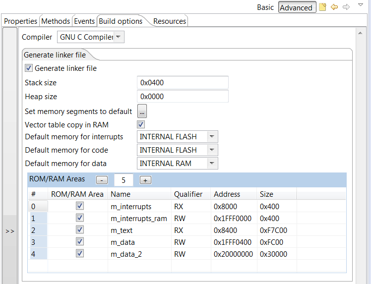
4) As i didn’t find the checkbox for “Flash Configuration Field” in CPU->properties, I opened the file startup_MK64F12.s and erased the lines where was written the following:
/* Flash Configuration */
.section .FlashConfig, “a”
.long 0xFFFFFFFF
.long 0xFFFFFFFF
.long 0xFFFFFFFF
.long 0xFFFFFFFE
(Procedure suggested as shown in page 12 of this document: KBOOT.pdf
5) Generated the .S19 file, downloaded to the board and right after jumping to the application address, nothing else happens…
I believe I’m quite close to the solution and there is a little detail that I didn’t get yet. Also, there was a strange behavior in this project because I couldn’t debug it properly. KDS was unable to start debugging from the main function address, it didn’t even set the breakpoint in the beginning.
So, what is the missing trick then?
LikeLike
Hi William,
I don’t spot any obvious mistake. Did you run the bootloader with the debugger? You should see how it jumps into the application code. Maybe something is missing there?
Erich
LikeLike
Well, after testing my adapted bootloader with a simple KSDK application, I have some conclusions:
1) In fact, it is possible to run a KSDK project after the bootloader jump. The project I was testing is a simple blink led. But there is something very particular when I try to put extra code in my project. In this same working project, i just tried to put two toggling leds and the project was no longer able to run…
2) Depending on the size of the S19 file, bootloader calls HardFault handler when it tries to record addresses at the end of the file…
If you have a FRDM-K64F in hands, and would like to help me in this issue, the related project files are in the link below. Bootloader project opens in CW and Blink_test opens in KDS. Also, there is a small terminal that I made to rush flash progress where terminal waits ack message from bootloader to send the next line. So that it’s not needed to put a 1ms delay between bytes sent.
https://www.dropbox.com/sh/58c24jor9rm5z9g/AABuLRNPF9NmRpsHGafxvo51a?dl=0
Hope you can help me. Thanks in advance.
William.
LikeLike
Hi William,
I don’t have a K64F board with me (I’m travelling right now). I try to have a look at your files next week when I’m back in the office.
LikeLike
Hi Erich!
Did you find some time to take a look at my files?
LikeLike
No, not yet 😦
LikeLike
Hi William,
finally I have found some time to look at your files, and I had taken with me a FRDM-K64F board while travelling. But when I tried your project, I see that you are using CodeWarrior, not KDS? I don’t have CodeWarrior installed on my machine right now as the notebook has been migrated to Windows 10. It will take me some more time to try this out on CodeWarrior.
LikeLike
Hi William,
I just see that your bootloader project is set up to a RAM target by default? Is this really the case for you on CodeWarrior (I loaded it into KDS).
Erich
LikeLike
Hi Erich!
If I knew you would discontinue using codewarrior for your projects, i would have migrated the whole BL project to KDS, but I just adapted the project available on your GItHub. Anyway, about the question, in CW the project apparently appears to be set up to flash target. This is what i see…
And please, tell me if it would be better for you to migrate this project to KDS. I can make it quickly.
LikeLike
I still have a few CodeWarrior projects, but they are for maintenance only. I have moved my ARM development to GNU and KDS nearly completely. So if you have that project for KDS, that would be easier for me for sure.
Erich
LikeLike
Ok, I’ll be waiting. Thank you, Erich.
LikeLike
Hi Erich,
I Just finished porting bootloader project to KDS, but things are getting worse…
The previous working blink leds that I put together in my dropbox folder (blink_test) is no longer running after loading srec file, and another project without ksdk (blink_test_no_ksdk) generates a srec file which is calling the hardfault handler during flash process. I believe the bootloader is well ported to KDS, you can check that out too.
Just waiting for good (or bad) news!
LikeLike
I have fixed the bootloader sequence and loaded the project here:
https://github.com/ErichStyger/mcuoneclipse/tree/master/Examples/KDS/FRDM-K64F120M/FRDM-K64F_Bootloader
So if you want to follow what I’m doing, you could check it there. Not sure how much time I will have today, but at least I’m able to run the bootloader itself (not tried to load application yet).
LikeLike
Ok Erich. Just checked your modifications. I wasn’t having problems on bootloader sequence, but i’ll follow your changes.
I see that our friend Nate is facing the same problems. Well, let’s wait and see what can be done.
Thank you!
LikeLike
I got it nearly working. I face hard faults if the flash block address is not 8byte aligned. I have it ‘fixed’ in the S19 file for now, but I need to check what the exact problem is. If the flash blocks in the S19 file are 8byte aligned, no problem.
I have it running with the Terminal.exe as in the blog post, as your terminal program crashes on my machine.
LikeLike
Nice to know that. I Suspected it could be the addresses misaligned, but I couldn’t know why. Do you know what is the reason for the tool to generate the S19 file like that? It is going to need a workaround in bootloader code to deal with it.
LikeLike
Oh God, you had the solution for all these problems in this post…
I’m so sorry for taking your time. If i knew it could be specifically related to the s19 file, I wouldn’t ask you so many question, and even asked you to see any projects. Now, that K64F bootloader project you commited needs a workaround to make misaligned s19 files work. If you still don’t have time to work on “third-parties” projects, i’ll try to submit a fix.
Thank you very much for everything!
P.S.: As i wrote that little terminal only for myself, i didn’t test it in other machines, but it’s very useful for large s19 files. So i’m gonna test it in other computers and OS to track bugs and exceptions.
LikeLike
Ah, you already found it 🙂
I admit that there could be more diagnostic information in the bootloader about failure points like this (I just added one additional one on the project on GitHub). I have used that way of bootloader for some slow OTA (over the air) updates where slow connection is not a problem (or a fact). What is not ideal right now that it flashes for every S19 line: having longer S19 files helps to avoid that. But I might consider to extend the bootloader to use a larger RAM buffer (e.g. 4 or 8 KByte). Will see if I can find time for this.
LikeLike
Hi William,
I have now extended the K64F project on GitHub with buffer handling, and it works that way fine (at least with my preliminary tests). I only have found that using the Segger USB CDC firmware was loosing some characters. Switching to the P&E OpenSDA firmware solved that problem.
I have added a blinky test program on GitHub in that K64F folder too.
LikeLike
Hi Erich,
I have one doubt. In the Screenshot titled, “Boot loader Flash Area”, you have configured m_text (Memory area 2) with address 410 and size 3BF0. At the end of this article in the screenshot titled “Application Flash Area”, you have configured the m_text (Memory Area 2) with address 40C0 and size 1BF40. Have you over-written the m_text area from address 410 to 40C0 and size from 3BF0 to 1BF40.. I am confused here.. Have you over-written that or is it separate memory areas for boot loader and application. If its separate, how is it done ?
Thanks
G.Ram
LikeLike
I have reduced the m_text area to the size of 0x3FB0. This is only to make sure that the application flash area starting at 0x4000 is not occupied by the bootloader.
LikeLike
Dear Erich,
My doubt was, At the beginning of the project, m_text area parameters are address 410 and size 3BF0 , at the end of the project m_text area parameters are address 40C0 and size 1BF40.
From your reply I understand like this.
So just for protecting the 4KB flash you are configuring m_text parameters to be 410 & 3BF0. Once the flash area for boot loader code is protected. You are allocating memory for application code (which is 40C0 + 1BF40) right ?
Thanks
G.Ram
LikeLike
Dear Erich
There are no errors now. But Terminal application is unresponsive to my commands. Kindly Check this link and guide me.
https://oscarganesh.wordpress.com/2016/05/04/terminal-application-is-unresponsive/
Thanks
Ganesh
LikeLike
Hey Erich.
Sorry for keeping on bugging you. But as I showed in this link, the bits are getting transmitted. Tx:0x26 as shown in my figure. But nothing is getting received Rx:0. In your article at the bottom of terminal app, it shows Tx:398 , Rx:32315. Can you spot out where my problem is ?
(https://oscarganesh.wordpress.com/2016/05/04/terminal-application-is-unresponsive/)
Thanks
Ganesh
LikeLike
Hi Ganesh,
you really need to hook up a scope/logic analyzer to your Rx and Tx lines and check them. The numbers in the terminal program won’t help you much if anything at all.
Erich
LikeLike
Hi Erich,
Thanks a lot for replying. I ll try your suggestion. But I have got one doubt Erich. I found you first, through this article of yours. https://mcuoneclipse.com/2014/10/06/putting-code-of-files-into-special-section-with-the-gnu-linker/
Now the LED blinking file (my application code) should be put in the application code starting address (0x1000) for successful loading through Terminal application ?
Thanks
Ganesh
LikeLike
Hi Ganesh,
you need to put your application where you have specified it in your bootloader: so if your bootloader fits below 0x1000 and you have specified that your application shall be at 0x1000, then that’s ok. But I think your bootloader might be something larger than 4096 bytes, so you need to adjust the memory range accordingly.
LikeLike
Dear Erich,
LikeLike
Dear Erich,
I forgot that my serial connection is RS 485. So I need to toggle it everytime I send and receive (Half Duplex).
For Rx
GPIO_PDD_ClearPortDataOutputMask(GPIOA_BASE_PTR, GPIO_PDD_PIN_21);
For Tx
GPIO_PDD_SetPortDataOutputMask(GPIOA_BASE_PTR, GPIO_PDD_PIN_21);
In which all places of the code should I include these lines Erich ?
And in terminal, since there is no RS 232 involved, is it enough If Xon/Xoff handshaking alone is selected ?
LikeLike
Hi Ganesh,
I have not used half duplex, so I guess you have to do this somewhere in the communication layer.
As for Xon/Xoff: I had mixed sucess with this, and it did not work well for me.
Better to slow down the data traffic.
Erich
LikeLike
Hey Ganesh,
Hi Erich Sir,
I am also using a half duplex connection only. I tried this code and got desired results
for(;;) { GPIO_PDD_TogglePortDataOutputMask(GPIOA_BASE_PTR, GPIO_PDD_PIN_21);
CLS1_SendStr(“Hello World!\r\n”, CLS1_GetStdio()->stdOut);
WAIT1_Waitms(1000);
CLS1_SendStr(“Welcome Bala!\r\n”, CLS1_GetStdio()->stdOut);
}
But I am unsuccessful when I try this code. It builds without any errors. It gets debugged inside the board without any errors. But when I press the Resume button, there is nothing in the Terminal Application.
static void ReadText(void) {
uint8_t buffer[32], ch, i;
for(;;) {
GPIO_PDD_TogglePortDataOutputMask(GPIOA_BASE_PTR, GPIO_PDD_PIN_21);
CLS1_SendStr(“Enter some text: “, CLS1_GetStdio()->stdOut);
buffer[0] = ‘\0′;
i = 0;
do {
if (CLS1_KeyPressed()) {
GPIO_PDD_TogglePortDataOutputMask(GPIOA_BASE_PTR, GPIO_PDD_PIN_21);
CLS1_ReadChar(&ch); /* read the character */
if (ch!=’\0’) { /* received a character */
buffer[i++] = ch; /* store in buffer */
if (i>=sizeof(buffer)) { /* reached end of buffer? */
buffer[i] = ‘\0′; /* terminate string */
break; /* leave loop */
}
if (ch==’\n’) { /* line end? */
buffer[i] = ‘\0’; /* terminate string */
break; /* leave loop */
}
}
}
} while(1);
GPIO_PDD_TogglePortDataOutputMask(GPIOA_BASE_PTR, GPIO_PDD_PIN_21);
CLS1_SendStr(“You entered: “, CLS1_GetStdio()->stdOut);
CLS1_SendStr(buffer, CLS1_GetStdio()->stdOut);
CLS1_SendStr(“\r\n”, CLS1_GetStdio()->stdOut);
}
int main(void)
{
PE_low_level_init();
}
Did you have any success Ganesh ?
Erich, do you have any suggestion for this ?
Thanks Ganesh and Sir
Looking forward to your replies sirs.
Bala
LikeLike
Hi Balam,
can you step through you code with the debugger to see what is going on?
Erich
LikeLike
Hi sir,
This is Bala. This article serves as the bible for a beginner who tries to design a boot loader. Kudos to your effort. I have few doubts sir. I am interested in designing boot loader for a Freescale’s KE-02Z controller.
1. Can this code be run in win_hc08sprog ?
2. Will the same logic work if I use a switch instead of a push button as BTLD button ?
Thanks sir.
Looking forward to hear from you
Bala
LikeLike
Hi Bala,
1. the win_hcs08prog is using a custom protocol, so you have to have this application running on the host. That’s exactly the reason why I wrote that serial bootloader which only needs a terminal program, and not a special application on the host. Bottom line: you cannot use the win_hcs08sprog for this bootloader.
2. the same logic works for any microcontroller, and any means of way to entering the bootloader. It can be any push button or pin, or any other way to signal to the bootloader that it needs to enter the bootloader mode.
I hope this helps,
Erich
LikeLiked by 1 person
Hi Sir,
Thanks a lot for your reply. Sir My last doubt. There is no main.c file in your project in GITHUB. With all due respect, How will the code run without a main() function ?
Correct me if am wrong, because I have never seen a code without main() function.
Thanks Sir
Looking forward to your reply sir
Bala
LikeLike
Hi Bale,
The main() function is in https://github.com/ErichStyger/mcuoneclipse/blob/master/Examples/CodeWarrior/FRDM-KL25Z/FRDM_Bootloader/Sources/ProcessorExpert.c. The name if the file is not relevant.
Erich
LikeLike
Hey Sir,
Sorry I thought it is some Processor Expert generated file. I am very sorry. My Boot loader code should be within 0x0000 to 0x1000 that is 4KB, But My Boot loader code size is
text data bss dec hex filename
8112 36 4068 12216 2fb8 Bootloader.elf
EVEN AFTER ENABLING THE OPTIMIZATION OPTION IN TOOL SETTINGS.
I am using KDS version 2. Can I reduce the code to less than 4KB. ? 😦
Thanks sir.
Looking forward for your reply sir.
Bala
LikeLike
Hi Bala,
well, reducing the from 8K to 4K for sure is not a simple thing. You would have to cut off features and functions to get there.
For example you would have to write your own flash programming library. That should reduce your code size. Or use a very minimal startup code.
Have a look at the linker .map file what is using the most space in your bootloader and try to optimize it.
LikeLike
Hi Sir,
I am just a beginner. So I don’t know if I can write my own flash programming library, or can modify my startup code. The only idea which I currently have in my mind is to change the boot loader memory allocation. At present I am trying to keep my boot loader code within 0x0000 to 0x1000 (4KB), I have to modify it to, 0x0000 to 0x2000 (8KB). And yea, again I have to change all the application code memory area.
Correct me if I am wrong sir.
Thanks alot sir.
Bala
LikeLike
Hello Erich, I’ve been doing work on a serial bootloader for a K64F board, using a few lines out of your example, in this case,
startup = ((uint32_t*)APP_FLASH_VECTOR_START)[1]; and
((void(*)(void))startup)();
I have ran into some strange issues, for instance, after loading the file and verifying all checksums for validity, the code is ran and immediately jumps to the unhandled interrupt breakpoint, 0xFF. this seems strange in that I don’t use the boot-loader, and instead run with the interrupt vector at 0x0000000, i do not encounter any errors. it only happens after changing the “to be loaded” codes interrupt vector up and attempting to load it. Any thoughts on what could be causing my issue? i did attempt to relocate the vector table with SCB_VTOR= (uint32_t)0x40000; at the address i store the “to be loaded” code, but I do not know if i did it correctly. For reference I have the vector start defined as this
#define APP_FLASH_VECTOR_START 0x40000
-Thanks for the help
Nate Hinshaw
LikeLike
Hi Nate,
not sure what it is, maybe I find out out with the K64F I’m doing right now.
Erich
LikeLike
Through further testing, i can tell that the application im loading in gets to the end of the while loop that contains its main running actions. Once it gets there, it seems to ignore that the loop is a while(1), and ends the loop, followed by the unhandled interrupt. is there something else that I need to do to properly jump to my application?
LikeLike
No, nothing special needed. Could it be that it is not the code running you are debugging? I would check and step the assembly code if it makes sense.
LikeLike
I fixed the issue I was previously having by making a new project with mostly the same code in it. I did overhaul the reading in of S19 files, but that was mostly to add a handshake between my flashing program and the board, with an echo back once the flash task was complete. Thanks for the help Erich, Your blog has been incredibly helpful
LikeLike
I am now running into the same hard fault, but for code that shouldn’t be causing a crash.
Flashing
S30D000457EC000000000114000096
followed by
S329000457F4EC57040000A0002008000000F45704000005FF1F0000000000000000000000000000000006
causes a hard fault on the side of the boot-loader. Memory maps are attached.
working memory map http://dumptext.com/ltPfs83q
hard fault memory map http://dumptext.com/MS9S6jM4
Those locations in memory appear to be for the __Data_ROM and the __m_data_1FFF0000_ROMStart locations
Is there something I am unfamiliar with that is causing this issue? Any help you could give would be greatly appreciated
LikeLike
Hi Nathaniel,
I cannot tell from the information. Maybe you can send me that S19 file or the KDS project to my email address (see https://mcuoneclipse.com/about/) and I might have a look at it?
Erich
LikeLike
Hi Erich,
Is there a way to debug the application (with the relocated vector table, etc) when a bootloader isn’t present? Say my application starts from address 0x8000, how can I get KDS to debug the application?
Thanks, Kevin
LikeLike
Hi Kevin,
It depends where your vector table is. Out of reset, it is at address 0x0000’0000. Are you saying that your application vector table is at 0x0000’8000? As for debugging, it all depends if your debug symbols are loaded in the debugger, and if they are at the right place/address of your code. I have not used relocatable code (yet) (if this is what you are asking for?).
I hope this helps,
Erich
LikeLike
Hello Eric sir,
I am using FRDM k64f board, I have configured project as the above blog.
But I am getting address 0x00(dword addr == 0) in following function:-
static bool BL_ValidAppAddress(dword addr) {
return ((addr>=MIN_APP_FLASH_ADDRESS) && (addr failed errors ….
May I know the exact values of address and size to be write in RAM/ROM area in Build option section….
I also downloaded the project from github…. and tested but no success…
Thank you…
Kishan
LikeLike
Hi Kishan,
if you get an address of zero in your application, then it probably means you have the vector table at address zero? This won’t work as the bootloader vector table is at that location, that’s why BL_ValidAppAdddress() is used to check this. You need to move your application vector table to the valid range. Have a look at the project in https://github.com/ErichStyger/mcuoneclipse/tree/master/Examples/CodeWarrior/FRDM-KL25Z/BL_Blink (but this is for CodeWarrior, btw).
LikeLike
Hello sir,
I am sorry that may be I am talking rubbish…. but how do I make vector table address to 0x4000
and second thing at starting in BL_CheckForUserApp(); function
if (startup!=-1 && !BL_CheckBootloaderMode()) function… this step is skipped by my controller while debugging….
as
/*(startup = 0xffffffff)
APP_FLASH_VECTOR_START = 0x40000*/
void BL_CheckForUserApp(void) {
uint32_t startup; /* assuming 32bit function pointers */
startup = ((uint32_t*)APP_FLASH_VECTOR_START)[1]; /* this is the reset vector (__startup function) */
/* at this stage startup becomes = 0xffffffff */
if (startup!=-1 && !BL_CheckBootloaderMode()) { /* we do have a valid application vector? -1/0xfffffff would mean flash erased */
((void(*)(void))startup)(); /* Jump to application startup code */
}
}
so controller is not checking weather BL_SW is pressed or not….
Thank you…
LikeLike
Hi Kishan,
have a look at the project link I have sent you: it is very easy that way and using Processor Expert, there is a setting in the CPU component.
The second question is related to that: that code checks the presence of the relocated vector table plus checks if the application is in bootloader mode or not.
LikeLike
Hello sir Thanks for reply….:)
Now Actually I am debugging the code as from your link given in github….
But now I am getting address 0x400 instead of 0x40000…
and at 0x400 it shows invalid flash address
Invalid flash address: 1024!
In mempry map from 0x400 to 0x410 is for Flash_config…
I think controller try program from address 0x400…
my config in program as follow..
#define MIN_APP_FLASH_ADDRESS 0x40000 /* start of application flash area */ //0x40000
#define MAX_APP_FLASH_ADDRESS 0x5FFFF /* end of application flash */
#define APP_FLASH_VECTOR_START 0x40000 /* application vector table in flash *///0x40000
#define APP_FLASH_VECTOR_SIZE 0x400 /* size of vector table */ // 0xc0
In my application program memory map is from
0x40000to0x40197 :- vector table adress and
0x40198 to 0x5FFFF as flash address …
What to do for address 0x40000…???
please make me correct if I am wrong anywhere…
Sorry for any inconvenience….
Thank you…
Kishan..
LikeLike
Hello Eric Sir,
I successfully uploaded s19 file via bootloader!!!…
But in my case Process took very much time to upload BLINK s19 file (Around 5 minutes)….
Is process is really slow or I am doing it wrong way……
Settings on terminal is as shown in blog…. (only Baud rate is 115200)
Also while uploading file before done message comes it will displays message as :
Erase sector at 0x40000
Program sector at 0x40000
done
CMD>.
(Which is not in your blog images)
After that BLINK program runs successfully….
Thanking you….
LikeLike
The flash programming in this example is not using buffering or any other optimization, so yes, it is not very fast.
LikeLike
Hello Erich Sir,
Today I tried Kinetis bootloader files and I successfully run that boot loader using “freedom_bootloader.bin” binary file. It will give flash FSL bootloader at USB K64f-J22 connector on FRDM board.. By using “KinetisFlashTool” upload .bin file to controller. It is running successfully….
Thanks for your help and your valuable time….!!!!
Regards,
Kishan
LikeLike
great! 🙂
LikeLike
Hi Erich, I’m attempting to pass the contents of a user application “bin” file over a serial port, 512 bytes at a time as part of a bootloader application. How can I use the IntFlash component and functions within this example to write these 512 byte blocks to flash? Is there a device-specific requirement as to the size of the blocks I can write all at once? I have all the code in which captures these 512 bytes of data, I’m just unsure of how to write them to flash. Thanks.
LikeLike
Hi Kevin,
I recommend that your read in and buffer that 512 bytes in RAM first, then write it to the FLASH with the SetBlockFlash() method of the IntFLASH component.
That component will care about the alignment and the necessary steps to program the FLASH. Have a look as well here: https://mcuoneclipse.com/2014/05/31/configuration-data-using-the-internal-flash-instead-of-an-external-eeprom/
I hope this helps,
Erich
LikeLike
Thanks Erich. So presumably, I just need to alter the block size accordingly for my MCU? Likewise (and for confirmation), I’m presuming that the flash address I pass into the function is my IMAGE_ADDR + offset (where offset is index * 512)?
LikeLike
Hi Kevin,
you don’t need to alter the block size. That flash function accepts a pointer to data, the size of the data and a pointer where to write the data. The component should take care about alignment and proper block erase.
Of course it is better if your blocks are already aligned, so the component does not need to make a backup, then erase and then write the flash.
LikeLike
Ok, thanks for your help Erich.
LikeLike
Hi Erich, sorry – another question. I’ve set my application so that its m_interrupts section starts at 0x10000 and m_text from 0x10410 (reducing the overall size as necessary). The output file is then converted to a bin. When I look at the contents of the bin file, the first 0x10000 bytes are almost all zero’s with the application data starting at 0x10000. Is there any way to get rid of this first part of the binary? Thanks.
LikeLike
Binary files are what they are: a binary dump of the memory. Intel Hex or S19 are much better (see https://mcuoneclipse.com/2012/09/27/s-record-intel-hex-and-binary-files/).
You could use the SRecord tool (see https://mcuoneclipse.com/2015/04/26/crc-checksum-generation-with-srecord-tools-for-gnu-and-eclipse/) and then only generate the binary from an offset (0x10000).
In your bootloader you need to know then that the offset is 0x10000 and start loading at that address.
LikeLike
Hi Erich, I’ve just read back my comment – please ignore it.
LikeLike
Is there any way to specify the endian-ness of the bytes loaded into the FTFL registers? For example, I’m writing my user program to flash as a bin file – when I come to jump to the user application, the bytes are reversed from the contents of the bin file.
LikeLike
I think you have to revert them in your loader.
LikeLike
Ok, thanks for confirming. I thought there may have been an option within the component to specify endianness – however having had some sleep, I’ve since discovered that this isn’t the issue. The issue is that occasionally, when the bin file is created, the values from location 0x10000 are all zero and I think it is to do with my linker configuration. Sometimes this is not the case but mostly, it is.
LikeLike
I’ve since realised that when I change the location of the m_interrupts section and the m_text sections (to 0x10000 and 0x10410 respectively) that the m_cfmprotrom location doesn’t change when the linker file is regenerated by PE. If I disable the re-generation of the linker file and then manually change the m_cfmprotrom location to 0x10400 then rebuild the application, the resulting bin file no longer contains data for addresses 0x00 to 0xFFFF, just data for 0x10000 onwards whereas before I changed the m_cfmprotrom I was getting everything including zeros in the SP and PC locations.
LikeLike
Hi Erich, I’ve now managed to get past all of the hurdles and can actually program a “bin” file in – correctly – over USB CDC. However – and its an annoying however. When I step through my bootloader to the point where it comes to jump to the user application address at location 0x10004 (I can confirm that the location contained at this address is 0x11FF1 (__thumb_startup) from my user application map file), execution shoots off to some random location. If I run the user application in the debugger though, it executes as expected from the same address (if I breakpoint on __thumb_startup). Any suggestions as to what could be going on? Thanks
LikeLike
Hi Kevin,
did you step through that jump code with assembly stepping (https://mcuoneclipse.com/2012/10/27/assembly-instruction-stepping/) and does that make sense? So I would expect it should load that 0x11ff1 into a register and do a jump on it?
I hope this helps,
Erich
LikeLike
Hi Erich, I didn’t actually try with assembly stepping. I just checked that the address loaded into the “jump” variable was of the correct location (which it was) and just jumped – I can check using this method though. One thing that’s been on my mind is interrupts – I don’t actually disable them before I jump so I’m wondering whether this is causing an issue, especially if the interrupt table is overwritten while interrupts are enabled.
LikeLike
Yes, good point: for the interrupts, the vector table has to be valid. So you should disable the interrupts before jumping to the new startup code.
As long as the vector table is fine, you should not see any issue. But it would be good to disable interrupts before jumping to the new startup code (actually they should be already disabled in the bootloader startup code, right?)
I would really do assembly stepping into the jump code to see what is going on.
LikeLike
Interrupts are enabled for a few peripherals in the bootloader (like the USB interrupt, I2C interrupt). I do want to relocate my vector table in user application space so I’m hopeful that an interrupt is causing this weird behaviour otherwise I’m completely at a loss. I’ll try the assembly stepping after I’ve disabled the interrupts. Thanks for your help
LikeLike
Damn those interrupts. Everything now works as expected once interrupts are disabled. Yippee 🙂
LikeLike
I’ve just checked the assembly in the instruction stepping and my jump is done via a “ldr r3, [r7, #4]” and “blx r3” which loads the correct address into r3 and successfully jumps to it. One thing I’m struggling with now is interrupts in user application space. For example, using the GenericI2C component gets stuck on the “while (!GI2C1_deviceData.dataTransmittedFlag);” so its clear that the I2C interrupt isn’t being fired. Previously when working with bootloaders in IAR, I just performed a jump to the user application and then interrupts, etc, just worked.
LikeLike
The Cpu.c takes care of the vector table relocation and I’ve checked (by breakpointing) that when SCB->VTOR is re-assigned, that it points to the correct location and I’ve also checked that the I2C ISR is pointing to the right place in user application space. I’m baffled!
LikeLike
Hi Kevin,
are interrupts globally enabled? I mean is the PRIMASK register set to zero?
LikeLike
Hi Erich, do you mean in the bootloader or in the user application?
LikeLike
In both, but this depends on the stage of each. During startup of the bootloader, interrupts shall be disabled.
Then they can be enabled during loading the image. But when jumping to the target application, I do disable them so the application startup code runs with interrupt disabled. The application startup code then will enable the interrupts (for the application).
LikeLike
In the bootloader, interrupts are enabled so that the I2C interrupt can fire (an i2c device is polled during the bootloader sequence). Prior to jumping to the application, I need to disable global interrupts or odd things happen when trying to jump and jumping is unsuccessful. When in the user application, I re-enable interrupts (__asm(“CPSIE i”) following PE_low_level_init but I never see the I2C interrupt fire (breakpoint is never reached in the ISR)
LikeLike
Hi Kevin,
after PE_Low_Level_Init(), are interrupts enabled? If not using an RTOS, they should be enabled at that point. If using an RTOS, they get enabled when you start the scheduler.
LikeLike
Hi Erich, straight after PE_low_level_init I’m calling __asm(“CPSIE i”) to enable interrupts
LikeLike
I suggest that you check with the debugger if the I bit in the PRIMASK is really cleared when you halt the user application.
If it the I bit is cleared, then it could be that maybe the interrupts for the I2C are not enabled?
LikeLike
I’ve taken everything back to basics and also removed the PE element of the application. My bootloader is now a small application which uses the SysTick interrupt to toggle an LED. After 10 seconds, a jump is attempted to a user application. When the bootloader starts, I enable interrupts and just before the jump, I disable them. In the user application, I again use the SysTick timer to toggle the same LED but I change the tick period so the LED flashes faster. As soon as the user app is entered, I can see PRIMASK is “1” and when I re-enable interrupts, it goes back to “0” – all this seems to work perfectly so I need to go back through my original code and try to figure out what I’m missing. I need to also try to get another interrupt working so I might try using the PIT timer in my user app.
LikeLike
Ok, I’m getting closer (I think). If I don’t enable interrupts in my main application but instead, if I step over the PE_low_level_init function and then, in the “registers” view, change PRIMASK from 0x1 to 0x0 and it run, the Cpu_ivINT_FTM1() interrupt is then hit and a breakpoint is triggered. However, the CPU is in the middle of a GI2C1_ReadAddress call so I’m figuring that the SCB->VTOR is not correctly aligned. Looking at the SCB->VTOR address, it is sat at 0x10000 which as expected so unless there is some serious alignment issue going on,
LikeLike
And if I don’t relocate my vector table in the linker config file (keeping it at 0x0000) then when I re-program, everything works perfectly.
LikeLike
Then I think something is wrong with that vector table? Can you try to have a 1-to-1 copy of your vector table from 0x0000 at 0x10000 (where you relocate it?).
LikeLike
So your PE_low_level_init() indeed enables interrupts at the end of that function. Is that what you intended? The VTOR must be aligned to a 1K or 4K boundary (I think), so this seems to be the case. Are you sure you have that relocated vector table correctly set up with all the entries, including initial PC and SP?
LikeLike
Hi Erich, problem solved. Vector table was correct and aligned properly, SP and PC were fine – the problem was me (as always). One interrupt was still enabled from the bootloader (funnily enough, it was FTM1) and now I’ve disabled it before the jump, everything works (everything, EVERYTHING :)). Thanks for all your help and sorry for my stupid questions
LikeLike
Glad to hear that things are working now!
My mission for every day: help an engineer out there. Accomplished for today I think 🙂
LikeLiked by 1 person
Hello, Erich
I tried to use your bootloader in FRDM-KL25Z, but it didn’t work. I realocated the memory in CPU bean Build Options, but I have not been successful to load my .s19 file. I don’t if this can be a problem, but as CodeWarrior keeps the Flash image file extension in .hex and only changes the contents to look like a .s19 file, I created a copy of .hex and just renamed the extension to “.s19”.
Anyway, I tried with both files, and it failed with both.
After loading “BL load s19”, it prints out:
“Erasing application flash blocks done!”
“Waiting for the s19 file”
Then, I click on “Send File”, pointing to my .s19 file path and that’s what I receive back on the Terminal:
“S0 address 0x00000000ERROR!”
“Failed at address 0x00000400”
“failed”
“Erasing application falsh blocks…done!”
“***Failed or unknown command: BL load s19”
“***Type help to get a lista of available commands”
“COM>***Failed or unknown command: S1134000003000209D480000C545000”
And this repeats for all the .s19 file lines.
My button is connected to PTD6. I changed this in Bootloader “Bit_IO” component.
Can you help us please?
LikeLike
Hello Marco,
at the address 0x400 there is the flash configuration of the bootloader itself: your application S19 file shall not have such a configuration in it: you need to build your application to be loaded without the flash configuration.
LikeLike
Ok. Now I understand that I have to use objcopy command for generating .s19 file acordingly, but I still don´t understand how to use this in CodeWarrior. Your tutorial explains how to do it in Eclipse Keppler. I tried it in CodeWarrior, but it didn’t work.
LikeLike
Hi Marco,
actually, this tutorial was written originally for CodeWarrior :-). Have a look at the BL_Blink project (https://github.com/ErichStyger/mcuoneclipse/tree/master/Examples/CodeWarrior/FRDM-KL25Z/BL_Blink) which creates such the S19 file. It uses the objcopy to generate the S19 file. For disabling the flash configuration, have a look in that project at the CPU component (Internal Peripherals > Flash Configuration Field : Disabled).
I hope this helps,
Erich
LikeLike
Hi, Erich
I don’t remember seeing a note about this Flash Configuration Field setting on this tutorial and realize now this is a default setting in CPU bean. This setting was crucial to have the bootloader recognizing my .s19 file and programming the MCU correctly.
Actually, “objcopy command” was not necessary to convert .hex extension of Flash image file into .s19. I just used .hex file generated by Codewarrior (actually formatted in .srec standard) and did not even rename it. And everything is running perfectly now!
Thank you very much for your help!
LikeLike
Hi Marco,
I appologize, indeed I had not pointed that out in a very visible way, because I thought that this might be obvious, so I was wrong about this. Thanks for asking that question, so hopefully everyone else bumping into this will be able to read this now.
Thanks again!
LikeLike
Hi, Erich
I’m trying to convert your FRDM-KL25Z bootloader into a FRDM-K22F bootloader for KDS. I could successfully move all the PE components settings from CW to KDS ( and just changed CPU to K22 and the pins used for led and button), as well as the additional files. No build errors. Now I face a new problem: KDS doesn’t have a configuration in CPU component that allows me to add user code before PE initialization. Do you know how can I do this in KDS?
Thank you very much!
LikeLike
I found out, Erich! In “startup.c” file, there is a function called “__init_user” that is reserved for user code and it is called before Processor Expert initialization. It is up and running now!
LikeLike
Great! Indeed, Processor Expert for some of the more recent Kinetis devices is different. Thanks for closing the loop!
LikeLike
Hello, Erich
We managed to convert your code to KDS for MK22FN512 (in other words to FRDM-K22F) and it worked! Now we are trying to convert your code for MK22FN1M0. We carefully followed the same steps as we did for MK22FN512, but after several attempts, we still couldn’t successfully load our code with the bootloader.
We created a simpler code to ease the tests like toggle a port connected to a buzzer. The bootloader logs down all the .srec lines and tell us the programming is successful, but as we put it to run, it doesn’t work.
We really don’t know where is the problem. I know it might be difficult to guess what is causing our failure, without our hardware and firmware. Could we send you our bootloader firmware so you can take a quick look on it? Maybe you can find something wrong that we’ve missed.
Thanks and best regards,
Marco Coelho
LikeLike
Hi Marco,
I don’t have the MK22FN1M0, but it could be that the flash blocks are different, or require different alignment?
It would be helpful if you could compare/dump the device memory after the programming to see what is differnt that your application does not run. You could dump the memory in different formats (e.g. S19), see https://mcuoneclipse.com/2012/05/04/dump-my-device-memory/
I hope this helps,
Erich
LikeLike
Hello, Erich
Actually, we had to change some definitions in “Bootloader.c” file regarding application’s Flash address range, Vector Table size, Erasable Unit Size, etc. The other settings are automatically regenerated by IntFlash bean and the other beans. The least we can erase in MK22FN1M0 are 32768 bytes blocks. So, we protect the first block from 0 to 0x7FFF. So, we allocate our application from 0x8000 on.
As we enter bootloader, we can load our application’s .srec file with no flaws (at least, no errors come up). After bootloader loads our .srec into Flash, we enter “BL status” command and can see that Flash range is correct and contents in 0x8000 are different from 0xFFFFFFFF, which signals something was programmed there.
Then, we enter BL restart command. Our application doesn’t run and bootloader itself dies. So, we can suppose that something corrupts all Flash memory and we lose everything, as bootloader jumps to the application.
Any idea?
Thanks and best regards,
Marco Coelho
LikeLike
Hi Marco,
I would run the bootloader with the debugger, and stepping through the application startup sequence to see what is going on.
LikeLike
Is it possible to have access to application source code after bootloader jumps to it in debugger? How can we do this? It is weird that Flash bootloader area was also corrupted, although it was entirely protected against erase and programming (0 – 0x7FFF).
LikeLike
Hello, Erich
We ran the bootloader with the debugger. The srec file loading was successful. But, if we enter “BL restart” command or do a power recycle (turn off and on the system), the application code doesn’t run. If we put a breakpoint in “BL_CheckForUserApp” function in the line:
((void(*)(void))startup)(); /* Jump to application startup code */
We can see the code gets there and jumps to our application. From this point on, debugger doesn’t allow us to run the code anymore, obviously because it can’t find application source code.
It is as if, after it jumps to application’s Flash, it corrupts all Flash memory, because we also completely lose access to bootloader.
Any idea?
LikeLike
Hi Marco,
it seems to me that your microcontroller is turning on some security features out of reset, making that memory area not accessible somewhow? Can you simulate a ‘restart’ with the debugger while bootloading your file? I mean debug the bootloader, let it program the application file, and then instead going through the BL restart (which will trigger a real reset), set the PC in the debugger to your bootloader startup code and step through the code to enter the application code. At least to verify that after bootloading the application binary is fine. If this is the case, and if it does not work after a reset, then really I think some protection feature is turned on after reset. I faced this kind of things with CRC settings on another microcontroller: it was using a CRC which was verified out of reset: the debugger wrote that correct CRC with programming the bootloader. But after loading the binary, the CRC did not match. I had to turn off that ‘CRC checking during device boot’ in the microcontroller.
I hope this helps,
Erich
LikeLike
Hello, Erich
We have already tried to execute “BL restart” command after loading our s19 file, and stepping through line by line from bootloder startup point to the point where it jumps to application code. It runs all the code perfectly.
Regarding Flash security settings, we checked this out. Bootloader Flash area (0 – 0x7FFF) security is disabled and in the case of application’s Flash are, Flash Configuration Field is disabled.
Now, I intend to try with FRDM-K64F, since MK64FN1M0 Flash memory is exactly the same as in MK22FN1M0.
Anyway, thank you for the tips!
LikeLike
Hello, Erich
I just tried on FRDM-K64K, but it didn’t work either. Also, I disabled Handshaking option in Terminal, but it doesn’t change a thing.
LikeLike
Hi Marco,
I have an example project here: https://github.com/ErichStyger/mcuoneclipse/tree/master/Examples/KDS/FRDM-K64F120M/FRDM_K64F_Bootloader
Plus a test project here: https://github.com/ErichStyger/mcuoneclipse/tree/master/Examples/KDS/FRDM-K64F120M/FRDM-K64F_Bootloader_Test
Have you seen these?
LikeLike
Hello, Erich
I just tried in my FRDM-K64F with your FRDM-K64F bootlloader firmware and test program you suggest, but I got errors when trying to load s19 file. It starts with:
“S0 address 0x00000000”
“Invalid Flash address: 32768”
And so on.
LikeLike
I found out the reason for the errors I commented before.
In FRDM_K64F_Bootloader, in Boootloder.c, memory settings were like this:
//#define MIN_APP_FLASH_ADDRESS 0x40000
//#define MAX_APP_FLASH_ADDRESS 0x5FFFF
//#define APP_FLASH_VECTOR_START 0x40000
//#define APP_FLASH_VECTOR_SIZE 0xc0
I corrected to the right values in order to match with FRDM-K64_Bootloader_Test Flash configuration:
#define MIN_APP_FLASH_ADDRESS 0x8000
#define MAX_APP_FLASH_ADDRESS 0xFFFFF
#define APP_FLASH_VECTOR_START 0x8000
#define APP_FLASH_VECTOR_SIZE 0x198
After this adjustment, I put it to run and it loaded FRDM-K64_Bootloader_Test .srec file successfully, and as I entered “BL status” command, it shows me there is something inside application’s Flash memory:
App Flash: 0x00008000..0x000FFFFF
@0x00008000: 0x20030000 0x00008BA1
But, if I try to jump to application, by entering “BL restart” or pressing reset button on Freedom, nothing happens.
LikeLike
Hi Marco,
it is hard to tell me what could be wrong without a reproducible case. Have you tried with my original example and example bootloader application I have put on GitHub?
And why did you have to change the APP_FLASH_VECTOR_SIZE?
LikeLike
Hello, Erich
My previous comments were based on attempts with your original example and example bootloader application you have put on GitHub.
Thanks!
LikeLike
Ok, Erich
I recognize I set Vector Size wrongly. The right value is 0x400. I corrected it, but the it keeps not working. Maybe you can reproduce the same failure on your side.
LikeLike
Hi Marco,
I’m sorry for not replying sooner, that thread was burried in my pile of emails :-(.
I have checked the project again, and I have to admit that the memory range on GitHub was at 0x5000 instead of 0x8000 from another test. I have fixed that and pushed the change to GitHub (https://github.com/ErichStyger/mcuoneclipse/commit/9b4268baf38c3870013972caf3c126509b91df06), and now it works on my side.
One thing to note is that I have sometimes problems with the Segger USB CDC implementation (it seems to loose characters), but it works properly with the P&E USB CDC and firmware on the FRDM-K64F board.
I hope this helps,
Erich
LikeLike
Hi Erich
I have just downloaded you latest mcuoneclipse_master package and tried again. The same problem: Terminal shows that bootloader apparently program the application into the MCU, but it doesn’t start the application after a reset. Besides, it messes up the Flash memory, because if you put the application to run, you don’t have access to bootloader anymore.
Just to inform you that I used both FRDM-K64F_Bootloader and FRDM-K64F_Bootloader_Test for KDS from your package in my test, just the way they are. I didn’t change anything. I couldn’t catch the problem by debugging, it happens exactly at the time it jumps to application.
LikeLike
Hi Marco,
strange, I have that problem now as well on my side. Not sure what is screwed up 😦
LikeLike
Ok, Erich
It is good to know that you could finally reproduce the same problem as me.
As soon as you solve this problem with your bootloader code and launch a new corrected version, please let me know.
Best regards!
LikeLike
Hi Marco,
I’m travelling right now, and I have ‘bricked’ my FRDM-K64F somehow and I need a Segger J-Link or P&E Multilink to regain access to the chip as OpenSDA fails, and I don’t have these with me. I have to check it when I’m back that the office next week, and of course I will report back my findings. Still scratching my head why this happens, as this was workign fine before 😦
LikeLike
Hello, Erich
It is a coincidence! I also have bricked my FRDM-K64F after some attempts. I was in holidays during those two last weeks and didn’t have a Multilink or USBDM at home, but now I’m back to office and I can try to recover the kit.
LikeLike
Hi Marco,
I was able to recover one board with the Segger J-Link. For the other I had to use the P&E Emergency Recover utility. I’m not clear yet what has caused the problem, I hope I can investigate it today or tomorrow.
LikeLike
Hi, Erich
Good to hear that you were able to recover your boards. I was not that lucky on my side.
I reprogrammed MK20 with MBED bootloader .s19 file that is available within your mcuoneclipse-master package and then I put FRDM-K64F into bootloader mode and reloaded it with P&E OpenSDA firmware again.
I checked in Windows Control Panel and apparently OpenSDA is working perfectly. Then I made a chip detection test with USBDM kit and I got a message “ARM target failed to power up”. That smells bad! To me, it looks like MK64 got into Flash security mode permanently and I can’t have access to Flash anymore.
Probably, I’ll have to replace the MK64 mounted in Freedom with a new one.
That is the only FRDM-K64F I have here at this moment 😦
LikeLike
Hi Marco,
I think more that the reset pin is somehow disabled.
Try the P&E Kinetis Recovery Tool (I think you have a P&E Multilink?): http://www.pemicro.com/support/download_processor.cfm?type=5 (requires login/registration into P&E site).
Have Segger or P&E (not mbed) firmware loaded on the K20 OpenSDA.
Run that that tool with the debug probe attached to the K64F SWD header, you might need to power cycle the board several times until the reset LED remains red.
Then download a ‘good’ application to the K64F using the K20 OpenSDA connection.
That worked on my side.
Good luck!
LikeLike
Should I power up the FRDM-K64F by OpenSDA port or the other (application) USB port?
LikeLike
I think I have used the OpenSDA port.
LikeLike
It seems that is not my case, Erich
I just run Kinetis Recovery Utility on my side with both Universal Multilink probe and USB cable connected to OpenSDA port.
The tool shows that both were detected. The last message is that it is continuosly attempting to halt processor and asks me to power recycle my board until the operation is successful. Although I have pressed reset button several and several times, it remains the same, but LED doesn’t remain red as I release reset button.
If I try to download an application to K64 with Multilink probe attached to K64 SWD header, it fails.
So, I guess it really is a issue with K64 MCU Flash.
LikeLike
you need to power cycle (remove power/USB cable) and plug it in again. Pressing reset is not enough. What happens is that the P&E Multilink pulls the reset line low all the time you try to power cycle the board. In the hope that when the microcontroller comes up, it hits the tiny window to halt the CPU. I had cases where I needed to power cycle the board about 60-70 times.
LikeLike
Hi Marco,
finally I spent some hours on that issue (which I still do not fully understand). For now I have disabled the interrupts/timer in the example projects, and now so far it is working. I have uploaded my S19 file as reference with the push here: https://github.com/ErichStyger/mcuoneclipse/commit/9fcf5640ea8ac4032b529ff4d7fdbb0ba2533cc7
I suspect is that I see some strange caching problem after programming the flash memory: what I read in the application from flash (e.g. from the vector table) does not match what I read with the debugger. Strange.
LikeLike
Hi, Erich
Thank you very much for your attention so far.
It really is very strange and it requires deep investigation. It is insane to think that the timer could be preventing the bootloader from writing the firmware correctly into target MCU!
I noticed that you made the following changes in Bootloader.c file:
-#define MAX_APP_FLASH_ADDRESS 0x1FFFF /* end of application flash */
+#define MAX_APP_FLASH_ADDRESS 0xAFFF /* end of application flash */
Have you noticed any problem related to the end Flash application address?
Thanks and best regards!
Marco Coelho
LikeLike
Hi Marco,
I only have reduced the FLASH area to simplify/minimize the application. I have not seen a problem with having 0x1FFFF as end address.
LikeLike
Pingback: “No source available”, or how to Debug Multiple Binaries with GDB and Eclipse | MCU on Eclipse
Hi Erich,
I´d like to know if the issue you were arguing with Marco Aurelio (porting the example to K64) was solved. In fact I´m the one who request that to him and originally I got the same problem but with a K22 (MK22FN1M0VLL12).
LikeLike
Hi Marcio,
unfortunately I have not found the root cause of the problem yet, and I’m not shure what else I should try out. Any ideas from your side?
Erich
LikeLike
I think probably must be something related to the flash region areas or its register and offsets on this architecture (1MB of flash), because both K22 and K64 we are using are very similar at this point and produce the same problem.
If I had another Kinetis NXP development here I´d try with a 256k or 2MB Flash CPU, but unfortunately I don´t. Did you do that before?
LikeLike
I only have the 1 MB Flash version.
LikeLike
Hi Erich,
In my application I want to activate the bootloader with a RFID TAG.
Because of the USB Stack, NFC Library I would like to use a Kinetis KL with min. 256kB Flash to have some buffer for the future. I use KDS3.2 and would like to use KSDK2x (Project just begins). I would like to use the example code for the MKL25 bootloader, but unfortunately I have not Codewarrior. I would like to adapt it to the KL27 with KSDK2.0. It would be great if you could help me, maybe you have a KDS Version of it?
Thank you
Jürgen
LikeLike
Hi Jürgen,
there is a port of that project available for the K64f (https://github.com/ErichStyger/mcuoneclipse/tree/master/Examples/KDS/FRDM-K64F120M/FRDM_K64F_Bootloader), but I (and others) are facing strange problems with the flash programming on K64 and K22 (still not resolved). You might have a look at this project.
As for using the SDK v2: keep in mind that this bootloader project is with Processor Expert, and the KSDK v2 does not support Processor Expert. So you could generate the code (say with the K64F project), but then you have to change it to work with the SDK V2 (e.g. providing your own flash programming code,etc).
LikeLike
Hi Erich,
Thank you for your reply. For me the most challenging is the massive source code overhead from NXP. I really prefer your solutions, they are simple and thought-out.
THe KL27x has a ROM bootloader, but the reason why I think about a Flash based solution is, that there will be a point in the future, where I want to transfer the binaries AES128 encrypted.
NPX provides the Kinestis bootloader in Version 2, which supports crypto transfer, unfortunately there are no code examples for the KL27x (designated for ROM Bootloader), but examples for the KL25 exists.
The built in Bootloader of the KL27 series provides all necessary parts except crypto transfer. I think the hardware modifcations in firmware is easier to do from KL25 to KL27 as the one from K64 to KL27.
I have seen that there are very much examples for the KL25 MCU. The hardware adaption for some KL25 projects to KL27 will be a first step for me, later I will do it with the NXP KL25 bootloader examples. I hope there are no massive errors hidden.
If I wouldn’t need the Flash size to be future safe, I would use the KL25.
Thank you
Jürgen
LikeLike
Hi Jürgen,
Did you manage to port this demo to KL27 with Processor Expert? I (and Erich) didn´t in a 1MB of flash (K22 and K64 respectively). I mean, the project itself seems to work fine, but after booting it doesn´t run the application. I´d like to know if with a 256kB you will get the same problem.
LikeLike
For everyone having problems with the flash programming: obviously (and that is new to me) some devices have a HSRUN (High Speed Run) mode, in which Flash programming does not work/fails. More information is https://community.nxp.com/message/898310?commentID=898310&et=watches.email.thread#comment-898310. As for my case of failing programming with the K64F: there is no such HSRUN, so not sure what is the problem here 😦
LikeLike
Hi Erich,
Thanks for sharing the information. In fact, for the K64F there is no HSRUN, but for the MK22FN1M0VLL12 there is. In that case what is the best clock settings (core, system, bus clock, etc.) to make this work?
LikeLike
I have not tried it with the MK22, but to my knowledge the HSRUN is clock configuration setting. So you could reduce the speed/change the settings for the bootloader so it does not use HSRUN? The application then later on can switch to HSRUN if needed, but the bootloader does not need to run at the highest speed.
LikeLike
Ok, I´ll try to do it at my side.
LikeLike
Erich, I was trying to port this demo to FRDM-K22 and everything was going well until I got stuck at this point: for the MK22FN512XXX12 I don´t have the “User Initialization” option on build options (Component options – CPU). Is there a way to activate it or something? I´m using KDS 3.2.0 for this job.
LikeLike
I solved this problem here, Marco Aurelio from Siletec help me and it´s all working now! From my porting (to FRDM-K22 and with KDS) I needed to call the BL_CheckForUserApp(); inside __init_user(void) function and include the “Bootloader.h” at the startup.c file. Do you want me to send you my project to you?
LikeLike
Hi Marcio,
if I can put that project on GitHub for everyone else, that would be great!
Erich
LikeLike
Ok, I´m doing that (putting the project to on GitHub) while I write this. I need to install GitHub yet…
For my application I also need to expand this demo (Using a memory stick to load the appliation file (USB MSD Host)) and to do that can I ask you for some help? Like, where do I start? Do I need the FreeRTOS to read the s19 file? Finally, any tips for this job will be very helpful ; )
LikeLike
Hi Marcio,
I would say that a USB MSD bootloader is probably not what you want. It puts a lot of dependency on the host (Windows, Linux, Mac, etc) and increases the size of the bootloader.
But you don’t have to use an RTOS like FreeRTOS for this, although you could.
Have you looked at the bootloader provided by NXP? Because my serial bootloader is really a simple and small one. If you are looking for more functionality, you probably better use the one provided by the NXP vendor.
Erich
LikeLike
Erich, what I want it to load the s19 file using your project example (Processor Expert feature) from a USB memory stick.
LikeLike
I think I can create my own “BL_LoadS19” to Flash the memory, but I have some doubts about it (I`m newbie): It´s only flashing an array line by line from the decoded srec file? What care should I take? It´ is possible to encrypt to avoid flashing from a spurios source?
Regards,
Márcio.
LikeLike
Hi Marcio,
while the S19 files is read in line-by-line, the loader is using a buffer to collect multiple lines and then program them all together for a flash page.
And yes, you can encrypt the file or secure it in any way you want. Just be aware that this will require extra computation power and RAM/FLASH space.
LikeLike
Pingback: Getting Started: ROM Bootloader on the NXP FRDM-KL03Z Board | MCU on Eclipse