
A bootloader on a microcontroller is a very useful thing. It allows me to update the firmware in the field if necessary. There are many ways to use and make a bootloader (see “Serial Bootloader for the Freedom Board with Processor Expert“). But such a bootloader needs some space in FLASH, plus it needs to be programmed first on a blank device, so a JTAG programmer is needed. That’s why vendors have started including a ROM bootloader into their devices: the microcontroller comes out of the factory with a bootloader in FLASH. So instead writing my bootloader, I can use the one in the ROM.

FRDM-KL03Z with ROM Bootloader
And as with everything, there are pros and cons of that approach.
Outline
Several of the newer NXP Kinetis microcontroller include a ROM bootloader. I have selected the NXP FRDM-KL03Z board for my experiments because it is inexpensive (less than $20) and a tiny microcontroller useful for smaller applications. And that KL03Z is present on the Ultimate Hacking Keyboard which sparked my interest. In this article I’ll share my experience and journey to use the ROM bootloader on the KL03Z (ARM Cortex-M0+, 32 KByte of FLASH. 2 KB SRAM in a 24QFN Package):

MKL03Z32VFK4 MCU
The source code used in this article can be found on GitHub (see Links section at the end).
Bootloader? Bootloader(s)!
The NXP Kinetis bootloader (KBOOT software) is available in version v2 (at the time of this article) on www.nxp.com/kboot. NXP provides three different variants:
- Flashloader: that bootloader is a ‘one-time-bootloader’ and resides in FLASH, either factory or user programmed. The bootloader area will be overwritten by the application, so the full FLASH memory is available to the application. But it is only possible to update the application one time, unless the application itself includes a bootloader. The Flashloader is interesting for programming devices without the need for a JTAG programmer. The KBOOT package comes with several example applications.
- Flash-Resident Bootloader: This bootloader is a ‘traditional’ bootloader which resides in FLASH memory. Source code is provided and I can fully configure it, but I need initially a JTAG programmer to program the device. The KBOOT package includes several example for different boards.
- ROM Bootloader: This bootloader is present on all Kinetis devices with a boot ROM, including the KL03Z. Basically it is a special version of the Flash-Resident Bootloader programmed into the ROM of the device. But no source files or any other information apart of the information in the reference manual is provided.
There are different ways how to communicate with the bootloader (I²C, SPI, UART, USB HID, USB MSD, CAN). The bootloader uses a special communication protocol, and the KBOOT software includes GUI and command line utilities to communicate with the device.
ROM Bootloader
The ROM Bootloader resides in the ROM starting at 0x1c00200 and uses some part of the RAM while the bootloader is running:

KL03Z ROM Bootloader memory map
💡 It would be useful to have the sources and memory map of the ROM bootloader available. That way, it would be possible to re-use some of the bootloader functions from the application to save FLASH space.
The bootloader could be called by the application with the following piece of code:
static void RunRomBootloader(void) {
	uint32_t runBootloaderAddress;
	void (*runBootloader)(void *arg);

	/* Read the function address from the ROM API tree. */
	runBootloaderAddress = **(uint32_t **)(0x1c00001c);
	runBootloader = (void (*)(void * arg))runBootloaderAddress;

	/* Start the bootloader. */
	runBootloader(NULL);
}
With the above code the application can enter the bootloader any time.
Booting
During POR (Power on Reset) or a normal reset it can be configured if the microcontroller enters the ROM bootloader or directly boots from the normal FLASH.
This is controlled by several things:
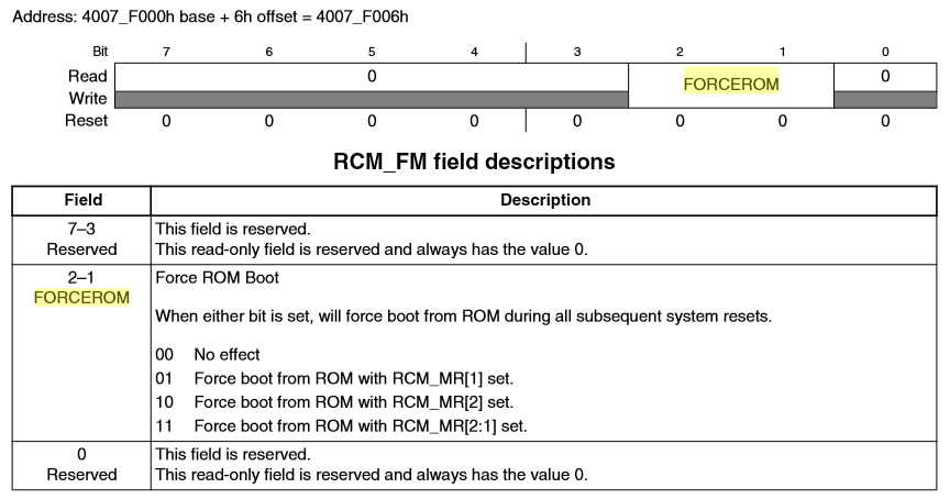
- FORCEROM: two bits used to always enter the ROM bootloader. If the bits are not zero, it always enters the ROM bootloader.

FORCEROM bits (Source: KL03P24M48SF0RM.pdf refrence manual)
- BOOTPIN_OPT: Part of the FOPT register. If this bit is zero, it enables checking an optional bootloader enable pin (NMI in the case of the KL03Z): if that pin is pulled low, it enters the ROM bootloader.

BOOTPIN_OPT (Source: KL03P24M48SF0RM.pdf refrence manual)
- BOOTCFG0 pin: This is the pin enabled by the BOOTPIN_OPT setting (NMI pin in case for the KL03Z).
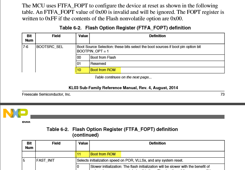
- BOOTSRC_SEL: Part of the FOPT register. If set to 10 or 11, then it enters the ROM bootloader:

BOOTSRC_SEL (Source: KL03P24M48SF0RM.pdf refrence manual)

Below is the diagram of the boot process:

Chip Boot Flow Chart (Source: KL03P24M48SF0RM.pdf refrence manual)
Entering Bootloader
So the ROM bootloader is entered if
- FORCEROM is set non-zero
- Or: A bootloader pin is configured with BOOTPIN_OPT and that pin is asserted (NMI)
- Or: BOOTSRC_SEL is set to 10 or 11
The NMI pin is on pin 19 of the KL03Z32VFK4:

NMI Pin on KL03Z32VFK4 (Source: FRDM-KL03Z schematics)
On the FRDM-KL03Z the NMI pin is routed to the SW3 push button:
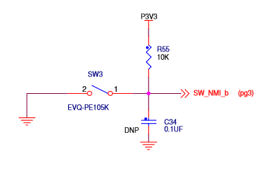
SW3 NMI Push Button (Source: FRDM-KL03Z schematics)
The button is present on the FRDM-KL03Z board here:
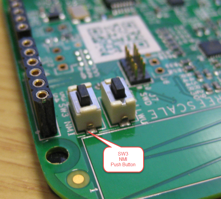
SW03 NMI Push Button on FRDM-KL03Z
Bootloader Pin Muxing
As outlined above, the NMI pin can be used to enter the bootloader. On which pins the bootloader can communicate is documented in the reference manual. The KL03Z can communicate over UART, SPI and I²C:
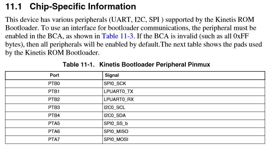
Bootloader Communication Pins
The UART (PTB1, PTB2) is routed to the OpenSDA USB CDC of the K20, and the the I2C (PTB3, PTB4) are available on the J2 header:

Bootloader UART and I2C Communication Pins
Bootloader Configuration Area (BCA)
The bootloader is configured by a structure located at 0x3C0 in FLASH (after the vector table starting at address 0x0:

Bootloader Configuration Area
BCA and Linker File
To configure the bootloader and the BCA, I use the following implementation:
💡 Note that the bootloader will select the first ‘working’ communication channel! I had an issue that on the I2C bus another device was sending data during bootloader boot-up, causing the bootloader listening to the I2C bus instead to the UART. I recommend only to enable the needed communication channels in the BCA settings.
/* bootloader_config.c
 * KBOOT ROM Bootloader configuration for FRDM-KL03Z Board
 */

#include <stdint.h>

#define ENABLE_BCA     (1)
  /*!< 1: define Bootloader Configuration Area mit magic number to use it from ROM bootloader; 0: use default setting (no BCA) */

typedef struct BootloaderConfiguration
{
    uint32_t tag; //!< [00:03] Magic number to verify bootloader configuration is
                  //! valid. Must be set to 'kcfg'.
    uint32_t crcStartAddress; //!< [04:07] Start address for application image CRC
                              //! check. If the bits are all set then Kinetis
                              //! bootloader by default will not perform any CRC
                              //! check.
    uint32_t crcByteCount; //!< [08:0b] Byte count for application image CRC
                           //! check. If the bits are all set then Kinetis
                           //! bootloader by default will not prform any CRC check.
    uint32_t crcExpectedValue; //!< [0c:0f] Expected CRC value for application CRC
                               //! check. If the bits are all set then Kinetis
                               //! bootloader by default will not perform any CRC
                               //! check.
    uint8_t enabledPeripherals; //!< [10:10] Bitfield of peripherals to enable.
                                //! bit 0 - LPUART, bit 1 - I2C, bit 2 - SPI,
                                //! bit 3 - CAN, bit 4 - USB
                                //! Kinetis bootloader will enable the peripheral if
                                //! corresponding bit is set to 1.
    uint8_t i2cSlaveAddress; //!< [11:11] If not 0xFF, used as the 7-bit I2C slave
                             //! address. If 0xFF, defaults to 0x10
                             //! for I2C slave address.
    uint16_t peripheralDetectionTimeoutMs; //!< [12:13] Timeout in milliseconds
                                           //! for active peripheral detection. If
                                           //! 0xFFFF, defaults to 5 seconds.
    uint16_t usbVid; //!< [14:15] Sets the USB Vendor ID reported by the device
                     //! during enumeration. If 0xFFFF, it defaults to 0x15A2.
    uint16_t usbPid; //!< [16:17] Sets the USB Product ID reported by the device
                     //! during enumeration.
    uint32_t usbStringsPointer; //!< [18:1b] Sets the USB Strings reported by the
                                //! device during enumeration.
    uint8_t clockFlags; //!< [1c:1c] The flags in the clockFlags configuration
                        //! field are enabled if the corresponding bit is cleared (0).
                        //! bit 0 - HighSpeed Enable high speed mode (i.e., 48 MHz).
    uint8_t clockDivider; //!< [1d:1d] Inverted value of the divider to use for
                          //! core and bus clocks when in high speed mode.
} bootloader_config_t;

/* bits for enabledPeripherals */
#define ENABLE_PERIPHERAL_UART     (1<<0)
#define ENABLE_PERIPHERAL_I2C      (1<<1)
#define ENABLE_PERIPHERAL_SPI  	   (1<<2)
#define ENABLE_PERIPHERAL_CAN      (1<<3) /* not supported for KL03! */
#define ENABLE_PERIPHERAL_USB_HID  (1<<4) /* not supported for KL03! */
#define ENABLE_PERIPHERAL_USB_MSC  (1<<7) /* not supported for KL03! */

/* Bootloader configuration area, needs to be at address 0x3C0! */
__attribute__((section(".BootloaderConfig"))) const bootloader_config_t BootloaderConfig =
    {
#if ENABLE_BCA
        .tag = 0x6766636B, //!< Magic Number
#else
	.tag = 0xFFFFFFFF, //!< No Magic Number
#endif
        .crcStartAddress = 0xFFFFFFFF, //!< Disable CRC check
        .crcByteCount = 0xFFFFFFFF, //!< Disable CRC check
        .crcExpectedValue = 0xFFFFFFFF, //!< Disable CRC check
        .enabledPeripherals = ENABLE_PERIPHERAL_UART, //ENABLE_PERIPHERAL_UART|ENABLE_PERIPHERAL_I2C|ENABLE_PERIPHERAL_SPI|ENABLE_PERIPHERAL_CAN|ENABLE_PERIPHERAL_USB_HID|ENABLE_PERIPHERAL_USB_MSC, //!< Enabled Peripheral: UART I2C SPI CAN USB-HID
        .i2cSlaveAddress = 0x10, //!< Use default I2C address(0x10)
        .peripheralDetectionTimeoutMs = 5000, //!< Use user-defined timeout(ms)
        .usbVid = 0xFFFF, //!< Use default Vendor ID(0x15A2)
        .usbPid = 0xFFFF, //!< Use default Product ID(0x0073)
        .usbStringsPointer = 0xFFFFFFFF, //!< Use default USB String
        .clockFlags = 0xFF, //!< 0 bit cleared: Enable High speed mode. NOTE: Enabling high speed mode makes UART connection worse or requires pull-up on Rx line!
	.clockDivider = 0xff, //!< Use clock divider(0)
    };

/* 16 bytes at address 0x400 */
__attribute__((used, section(".FlashConfig"))) const uint32_t FOPTConfig[4] = {
  0xFFFFFFFF,
  0xFFFFFFFF,
  0xFFFFFFFF,
 // 0xFFFF3DFE // boot from FLASH
  0xFFFFBDFE   // boot from ROM, means this will kick in the bootloader by default
};
💡 Be careful with the FlashConfig (FOPT) configuration! If not done right, you might brick your part! See “How (not) to Secure my Microcontroller“
Using the macro
#define ENABLE_BCA (1)
 /*!< 1: define Bootloader Configuration Area mit magic number to use it from ROM bootloader; 0: use default setting (no BCA) */
I can turn on/off the BCA. If turned off (set to 0), the BCA signature will not be used, and the bootloader ignores the BCA.
The BootloaderConfig variable needs to be allocated in FLASH at address 0x3C0. For this I have allocated a MEMORY area
m_bootloader_config (RX) : ORIGIN = 0x000003C0, LENGTH = 0x20 /* ROM Bootloader configuration */
with the corresponding placement in the linker file (see “Defining Variables at Absolute Addresses with gcc“):
/* placing my named section at given address: */
.myBootloaderConfigBlock :
{
 KEEP(*(.BootloaderConfig)) /* keep my variable even if not referenced */
} > m_bootloader_config
Same for the Flash Configuration (FOPT): declared a memory area:
m_flash_config (RX) : ORIGIN = 0x00000400, LENGTH = 0x00000010 /* Flash configuration options (FOPT) */
and placed it in the linker section like this:
.flash_config :
{
 . = ALIGN(4);
 KEEP(*(.FlashConfig)) /* Flash Configuration Field (FCF) */
 . = ALIGN(4);
} > m_flash_config

Bootloader and Flash Configuration in Linker File
Erasing BCA and FLASH
If that configuration area is not properly set up, then running the bootloader might fail. I highly recommend to erase the KL03Z flash starting playing with the FRDM-KL03Z board, as the preloaded demo application seems to confuse the bootloader. To erase the FLASH, I’m using the SEGGER OpenSDA firmware and the SEGGER J-Link J-Flash Lite program which is free of charge for non-production purposes:
Select the device:

SEGGER JFlashLite Device Detection
Then erase the chip:

Erasing the Chip
With this, the BCA is erased and set to default 0xFF memory pattern.
Connecting to Bootloader over UART
To make an initial connection to the ROM bootloader after erased the FLASH, connect a USB cable to the OpenSDA USB port:

USB USB CDC Connection
Determine the virtual COM port (e.g. using the Windows Device Manager):

COM Port in Device Manager
If using the P&E OpenSDA Debug connection, then the serial port will show up as ‘OpenSDA – CDC Serial Port’:

PnE OpenSDA Serial Port
Then do a Reset while the SW3/NMI pin pulled LOW:
- Press and hold the Reset button
- Press and hold the SW3 button
- Release the Reset button while still holding the SW3 button
- Release the SW3 button

Enter ROM Bootloader Mode
There is no visual sign at all to show that the microcontroller is in bootloader mode now.
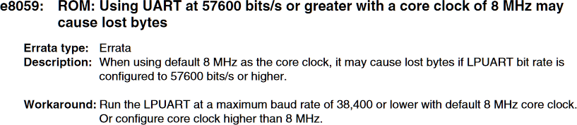
NOTE: There are several issues with the ROM bootloader, see the following errata:
Errata e8059
Because of this, I only was able to connect with 19200 baud (and not always!). So make sure you are using 19200 baud!
To connect to the board use the KinetisFlashTool (GUI) or blhost (command line tool).
💡 Both the used communication channel (I2C, UART, SPI) and the speed (baud) is selected at the first communication attempt. To change the communication speed or communication channel, the KL03Z has to be reset first!
The KinetisFlashTool (for Windows) is located in
<KBOOT Installation path>\NXP_Kinetis_Bootloader_2_0_0\bin\Tools\KinetisFlashTool\win
The blhost tool is located in
<KBOOT Installation path>\NXP_Kinetis_Bootloader_2_0_0\bin\Tools\blhost

KinetisFlashTool
Then press ‘Connect’, and hopefully it connects (otherwise retry):

KinetisFlashTool Connected to Device
With the blhost command line tool, use
blhost --port COM9,19200 -d -- get-property 1
💡 Make sure that the COM port is not already used (close the KinetisFlashTool).
The -d option produces some debug output, and with get-property 1 I ask for the bootloader version information.
The first command after power-on might lost (yet another entry in the errata): In that case, cancel the command with CTRL-C:
blhost --port COM9,19200 -d -- get-property 1

Warning: Operation canceled!
- The target device must be reset before sending any further commands.
^C
Then try it again, the second time it usually works:
blhost --port COM9,19200 -d -- get-property 1
[5a a6]
<5a>
Ping responded in 1 attempt(s)
<a7>
<00 00 01 50 00 00 29 ae>
Framing protocol version = 0x50010000, options = 0x0
Inject command 'get-property'
[5a a4 0c 00 4b 33 07 00 00 02 01 00 00 00 00 00 00 00]
<5a>
<a1>
<5a>
<a4>
<0c 00>
<07 7a>
<a7 00 00 02 00 00 00 00 00 00 01 4b>
Successful response to command 'get-property(current-version)'
 - took 0.009 seconds
[5a a1]
Response status = 0 (0x0) Success.
Response word 1 = 1258356736 (0x4b010000)
Current Version = K1.0.0
Success! We are able to talk with the bootloader!
I was further able to improve above situation after considering the e8086 in the errata:
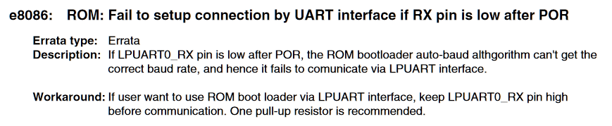
e8086 KL03Z errata
So I added a 10K pullup to the LPUART Rx pin:
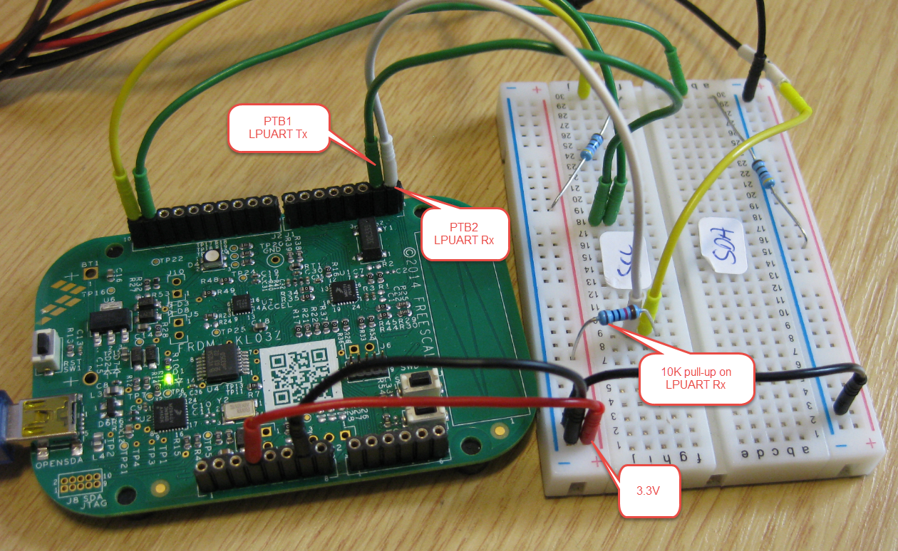
10k Pull-Up on LPUART Rx Pin
Enabling Higher Baud for UART Connection
With lots of trial-and-error, I managed to get a stable bootloader UART connection. Here is what I did:
- Added 10k Pull-Up resistor to LPUART Rx Pin
- Setting BCA clock flags to 0xFE: .clockFlags = 0xFE
- Setting BCA cock divider to 0xFF: .clockDivider = 0xff
- Reset and enter bootloader with above settings
That way I have been able to use for example 57600 🙂 :
blhost --port COM9,57600 -d -- get-property 0x2
[5a a6]
<5a>
Ping responded in 1 attempt(s)
<a7>
<00 00 01 50 00 00 29 ae>
Framing protocol version = 0x50010000, options = 0x0
Inject command 'get-property'
[5a a4 0c 00 3e fb 07 00 00 02 02 00 00 00 00 00 00 00]
<5a>
<a1>
<5a>
<a4>
<0c 00>
<2d c6>
<a7 00 00 02 00 00 00 00 01 00 00 00>
Successful response to command 'get-property(available-peripherals)'
 - took 0.013 seconds
[5a a1]
Response status = 0 (0x0) Success.
Response word 1 = 1 (0x1)
Available Peripherals = UART
Loading a binary with the bootloader
I have put on GitHub three blinky programs you can use to test the bootloader:

ROM Bootloader Test Programs
If using the Flash tool, browse for the image file and use the Update button:

Updating Image File with KinetisFlashTool
The same with the blhost command line utility looks like this:
blhost --port COM9,57600 write-memory 0 "FRDM-KL03Z_LED_blue.bin"
If using S19/S-Record files, there is the ‘flash-image’ command:
blhost --port COM9,57600 flash-image "FRDM-KL03Z_LED_blue.srec"
However, I had bad luck with these, they returned an error: kStatus_FlashCommandFailure
blhost --port COM9,57600 write-memory 0 "c:\tmp\FRDM-KL03Z_LED_blue.bin"
Ping responded in 1 attempt(s)
Inject command 'write-memory'
Preparing to send 14784 (0x39c0) bytes to the target.
Successful generic response to command 'write-memory'
(1/1)24%Data phase write aborted by status 0x2712 kStatus_AbortDataPhase
Response status = 105 (0x69) kStatus_FlashCommandFailure
Wrote 3616 of 14784 bytes.
Only until by trial-and-error I have found out that if I do an flash-erase-all first it succeeds:
blhost --port COM9,57600 -d -- flash-erase-all
[5a a6]
<5a>
Ping responded in 1 attempt(s)
<a7>
<00 00 01 50 00 00 29 ae>
Framing protocol version = 0x50010000, options = 0x0
Inject command 'flash-erase-all'
[5a a4 08 00 0c 22 01 00 00 01 00 00 00 00]
<5a>
<a1>
<5a>
<a4>
<0c 00>
<2d 84>
<a0 00 08 02 00 00 00 00 01 00 00 00>
Successful generic response to command 'flash-erase-all'
 - took 0.034 seconds
[5a a1]
Response status = 0 (0x0) Success.
Then do the programming:
blhost --port COM9,57600 write-memory 0 "c:\tmp\FRDM-KL03Z_LED.bin"
Ping responded in 1 attempt(s)
Inject command 'write-memory'
Preparing to send 17544 (0x4488) bytes to the target.
Successful generic response to command 'write-memory'
(1/1)100% Completed!
Successful generic response to command 'write-memory'
Response status = 0 (0x0) Success.
Wrote 17544 of 17544 bytes.
I have no explanation, as nothing in my flash was protected or secured. At least I have found a way to get it working 🙂
Summary
A ROM bootloader is a nice thing: I don’t need to reserve FLASH space for the bootloader. Instead the bootloader is burned into the ROM and I can communicate to it with I²C, UART and SPI on the NXP KL03Z. Be aware of the errata, and with the right steps and connection settings it should hopefully work.The KL03Z device errata affects several parts of the ROM bootloader, requiring some workarounds.
What’s next? I’m currently exploring and using the BusPal technology: this part is really interesting, as it allows to use a microcontroller to interface with the bootloader of another microcontroller. That way, one device can update another. The NXP provided projects are for IAR and Keil, but I have managed to port BusPal to the FRDM-KL25Z using free and open GNU tools. So this could be the topic of a next article?
I hope this article is useful for you to get started with the bootloader on the FRDM-KL03Z or any other board. And don’t forget to always check the errata of your device ;-).
Happy Bootloading 🙂
Links
- Kinetis Bootloader and Tools download page: www.nxp.com/kboot
- Source code used in this article on GitHub: https://github.com/ErichStyger/mcuoneclipse/tree/master/Examples/KDS/FRDM-KL03Z/FRDM-KL03Z_LED
- NXP Freedom boards: http://www.nxp.com/freedom
- FRDM-KL03Z board: http://www.nxp.com/products/software-and-tools/hardware-development-tools/freedom-development-boards/freedom-development-platform-for-kinetis-kl03-mcus:FRDM-KL03Z
- FRDM-KL03Z errata: http://www.nxp.com/docs/en/errata/KL03Z_1N86K.pdf
- Ultimate Hacking Keyboard: https://ultimatehackingkeyboard.com/
- Serial Bootloader: Serial Bootloader for the Freedom Board with Processor Expert
- Terminal program for bootloaders: Swiss Army Knife of Terminal Program for Serial Bootloaders

Hi Eric,
Thank you for this article. It is very good, concise and summarizes well the challenges one might have in getting to run the KBOOT from ROM (Also it compresses the reading of all the documentation from NXP in one nice article.). Well done!
I’ve been looking at KBOOT from ROM for the KL82.
I agree with your note that “It would be useful to have the sources and memory map of the ROM bootloader available.” . I have asked already NXP for this: https://community.nxp.com/thread/455053 . Seems that they are not willing to share this info. Pity, because, as you said, one could save code space.
Looking forward for the next article, about BusPal.
Best wishes,
Radu
LikeLike
Hi Radu,
thanks :-). As for the memory map of the ROM bootloader: I can step through the assembly code, and it very much looks the same as the Flash bootloader. So with some reverse engineering, it would be possible to get the entry points of the functions used. But that would be specific for each ROM bootloader, so has to be done for each implementation.
Erich
LikeLike
What purpose does it serve NXP to make this information hard to get?
In one case they actually threatened a lawyer attack as an answer to a question about getting GUI source code.
Knowing what RAM the bootloader may trash is sometimes required if want to preserve variables across resets.
LikeLike
Obviously I cannot answer the first question. But what RAM is used be bootloader is documented in the KL03 reference manual (yes, it was not easy for me to find it): pate 109 of KL03P24M48SF0RM.pdf, Figure 11-1 Kinetis Bootloader ROM/RAM Memory Maps. According to this, the bootloader uses the RAM from 0x1fff’fe00 to 0x2000’020E.
I hope this helps,
Erich
LikeLike
Huge thanks in the name of the whole UHK team, Erich! I’m so glad that you’re exploring this territory and sharing your findings. I’ve written about BusPal in a recent UHK blog update. Hope you find it interesting. Cheers!
LikeLike
Anyone been using the KBoot HID? I’ve run into to three significant problems with it.
A) “blhost -u$(VID),$(PID) reset” does not work.
The ‘reset’ commands put KBoot in to a loop of incomplete enumeration cycles requiring a physical reset or power down.
B) The default time to wait for the bootloader is to short for Windows to install the actual HID device driver. It says “Device Unplugged” during the install process. I’ve see Windows take well over a minute to complete this driver install process, even when not searching Windows Updates that can add even more minutes. A longer default time could be set in the BCA, yet who wants to wait minutes for their embedded device to boot? Any way to speed up Windows install process? Only real difference between this device and any other installed generic HID is the VID/PID. Would seem there should be a way to copy and existing one in the registry.
C) The KBootGUI does not work on all computers. About 50% of the computers I’ve tried to run the KBootGUI on do nothing. That is the icon is clicked to start the program and it acts exactly like the icon was never clicked. No program, no errors, nothing at all happens. Any ideas why? blhost has worked on every computer.
LikeLike
The KL03Z does not have USB, so does not have the HID bootloader feature. I tried it (to less extend) on the FRDM-K22F, but that’s a Flash resident bootloader and not the ROM bootloader, and I have not seen the issue there you describe. Which device did you use? The Windows install process only seemed to happen one time for me, and was faster the second time.
Anyway I believe any bootloader which uses something more fancy than a UART might run into problems, especially anything with USB: there are simply too many traps with USB bootloaders in my view, so I prefer UART over anything else.
What I did is porting the BusPal to the FRDM-KL25Z, so it can act as an ‘intelligent’ loader. I’m thinking that I could add a SD card to it and use it as a loader from SD card over UART to the device.
About KBootGUI: I did not had issues on my machine (Windows 10). I’m aware of at least one issue with blhost on Mac (which I don’t use): https://community.nxp.com/thread/453944
I hope this helps,
Erich
LikeLike
It is the KL27 that I’m using which is also based on KBoot.
A USB connector is already on the device for other reasons which is why did not go with serial.
LikeLike
Regarding B), I’ve experienced the issue, but did not try to reproduce it again. According to my knowledge, the maximum KBOOT timeout is about a minute which might not be enough for Windows in some cases. Maybe the best way is to run an application that looks for the device and pings KBOOT. That way, it’d run indefinitely. The question is whether this is possible until the device driver is installed.
LikeLike
In my opinion, that timeout feature is something which probably should not be used. First it delays starting up the application, and as pointed out, there is a limit of the amoung of milliseconds (16bit variable, so indeed only a little bit more than one minute to wait). The always better approach is to check for some trigger (push button pressed/etc) in the application main() after reset and then enter the bootloader mode if triggered.
This requires a way to trigger (e.g. push button or jumper), but thats something worthwile to spend.
LikeLike
I totally agree with the trigger feature. I meant that a long timeout may be useful once the bootloader is triggered, but maybe it’s a better approach to stay in the bootloader forever once is triggered. This may depend on the application.
LikeLike
What I always provide is a way (usually jumper or push button) to enter the bootloader and a push button for reset.
If two buttons/pins are available, that is the ideal solution.
In some designs I’m using the reset button both for reset and entering the bootloader:
after power on, the reset pin is configured as reset pin (as usual). Then in main(), after a delay of 1 or 2 seconds the reset pin get muxed as GPIO input pin. That delay is necessary to allow a debugger to assert the reset line to connect to the application after reset. After that delay, the application muxes the pin as input pin: if it is asserted say up to 5 seconds after reset, it enters the bootloader. After that 5 seconds delay, the pin is muxed back to the reset function. That way only one pin is needed and allows a flexible handling of bootloader and application entry.
LikeLike
Thanks Erich! I like the two button approach for dev boards, but the one button implementation is easier from a user standpoint for consumer electronics products.
LikeLike
Pingback: Further steps towards mass production – Ultimate Hacking Keyboard
Micro-typo: In the example code block following the sentence “Same for the Flash Configuration (FOPT): declared a memory area:”, it appears that you have a small copy/paste error: Where it says “m_bootloader_config (RX) : ORIGIN = 0x000003C0, LENGTH = 0x20 /* ROM Bootloader configuration */”, I think that should be “m_flash_config (RX) : ORIGIN = 0x00000400, LENGTH = 0x10”
One question: is it possible to do math expressions, such as “LENGTH = 0x8000 – 0x410”? I could swear I’ve seen that done somewhere, but not sure if it applies to .ld files.
LikeLike
Thanks for finding that copy-paste bug! Fixed now :-).
And yes: you can use some basic math in linker script files. For example I have used it in https://mcuoneclipse.com/2017/09/06/using-the-gnu-linker-script-to-know-the-flash-and-ram-areas-in-the-application/
LikeLike
Super-helpful post!
For reasons unknown, I found that simply declaring the .bca section “KEEP” in the .ld file was not sufficient to prevent the linker from pruning the BootloaderConfig table. Instead, I also had to invoke the GNU-specific “used” attribute when instantiating the table:
__attribute__((section(“.BootloaderConfig”)))
__attribute__((used))
const bootloader_config_t BootloaderConfig =
{…}
For more history and details, see https://community.nxp.com/message/949979?commentID=949979#comment-949979
LikeLike
I’m not sure why it worked for me, but it did. But I know that these kind of things might depend on the toolchain/gcc version used. Indeed, it might be the best if both KEEP and (used) are used together. I always check the map file.
LikeLike
One thing that has bedeviled me (see https://stackoverflow.com/questions/46799907/extending-srecord-to-handle-crc32-mpeg2/46947352#46947352 and comments in https://mcuoneclipse.com/2015/04/26/crc-checksum-generation-with-srecord-tools-for-gnu-and-eclipse/) is how to generate the proper CRC32 to insert in the .crcExpectedValue field of the Bootloader Configuration Area. (Our app *really* needs CRC validation since its only communication with the outside world is a serial port: no JTAG, no reset button…)
It turns out you CAN coerce srec_cat into producing the correct CRC32 for the Kinetis Bootloader 2.0 protocol as follows:
$ srec_cat test.srec -Bit_Reverse -CRC32LE 0x1000 -Bit_Reverse -XOR 0xff -crop 0x1000 0x1004
If you’ve read Erich’s nifty article on srecord, you’ll know what all those command line arguments mean! 🙂
LikeLike
Thank you so much for posting the solution! I’m sure I will need that one very soon, as one of my next projects is supposed to use the Kinetis Bootloader too.
LikeLike
Pingback: Flash-Resident USB-HID Bootloader with the NXP Kinetis K22 Microcontroller | MCU on Eclipse
Pingback: Tutorial: CRC32 Checksum with the KBOOT Bootloader | MCU on Eclipse
Hi Erich,
I’ve got a project that uses the KL27 as a host processor, with the KL03 as a slave. I’d like to start using the ROM bootloader so the host can update the slave firmware – ie, using a microprocessor instead of the KBOOT program on a PC. In getting this bootloader working for your purposes, have you come across any resources for getting this to work – example host code, app notes etc? As you mentioned, the TRM is pretty thin on detail…
thanks!
Iain
LikeLike
Hi Iain,
I have worked on the Ultimate Hacking Keyboard which uses a K22 as host and a KL03Z as a slave. Have a look at https://github.com/UltimateHackingKeyboard
I hope this helps,
Erich
LikeLike
excellent, thanks Erich!
LikeLike
Pingback: Regaining Debug Access of NXP i.MX RT1064-EVK executing WFI | MCU on Eclipse
Hi Erich,
first of all thanks you for your post! I’m trying to use the ROM Bootloader of KE18F but hard faults make me cry… I found where the problem is, but idk what is it.
When I try to config BCA the initial value to configuration is Magic Number and it’s configured correctly with a value of 0x3C0, but in the next code line (it does not matter which) the program enter on a Hard Fault.
I hope you have understood me, because my english is so basic. Anyway I put the code that I used for config BCA:
/* Bootloader configuration area, needs to be at address 0x3C0! */

#define BOOTCONFIG_BASE	(0x000003C0)

#define BOOTCONFIG	((bootloader_config_t*)BOOTCONFIG_BASE)
void bootloaderconfig_ (void)
{
#if ENABLE_BCA
BOOTCONFIG->tag = 0x6766636B;
#else
BOOTCONFIG->tag = 0xFFFFFFFF, //!crcStartAddress = 0xFFFFFFFF;
BOOTCONFIG->crcByteCount = 0xFFFFFFFF;
BOOTCONFIG->crcExpectedValue = 0xFFFFFFFF;
BOOTCONFIG->enabledPeripherals = ENABLE_PERIPHERAL_UART;
BOOTCONFIG->peripheralDetectionTimeoutMs = 1000;
BOOTCONFIG->clockFlags = 0x01;
BOOTCONFIG->clockDivider = 0xFF;
}
int main(void) {
/* Init board hardware. */
BOARD_InitBootPins();
BOARD_InitBootClocks();
BOARD_InitBootPeripherals();
/* Init FSL debug console. */
BOARD_InitDebugConsole();
pin_Yellow_INIT(GPIO_configOutputH);
pin_Green_INIT(GPIO_configOutputH);
pin_SW2_INIT(GPIO_configInput);
PORT_SetPinInterruptConfig(BOARD_INITPINS_SW2_PORT, BOARD_INITPINS_SW2_PIN,kPORT_InterruptFallingEdge);
EnableIRQ(PORTD_IRQn);
NVIC_SetPriority(PORTD_IRQn, 5);
bootloaderconfig_();
/* Force the counter to be placed into memory. */
volatile static int i = 0 ;
/* Enter an infinite loop, just incrementing a counter. */
while(1)
{
i=2371603;
while(i)
i--;
pin_Yellow_TOGGLE();
}
return 0 ;
}
LikeLike
Hi Jan,
I probably would need such a KE18F board, but…
I see you are calling bootloaderconfig_()? The bootloader configuration is a constant structure in FLASH, and you cannot write to that at runtime (well, without proper flash programming).
So it is for sure not working, and a hard fault is what I expect for something like this (you try to write to read-only memory!).
Have a look at my KL03Z application and source code in this article: I have a constant structure placed in flash to configure the bootloader, that’s the way it is supposed to work.
I hope this helps,
Erich
LikeLike
Pingback: Linking Bootloader Applications with Eclipse and FreeMarker Scripts | MCU on Eclipse
Hi Erich,
I followed this blog
Actually I am using FRDM_KL27Z board,
I called bootloader function from application with the following piece of code:
static void RunRomBootloader(void) {
uint32_t runBootloaderAddress;
void (*runBootloader)(void *arg);
/* Read the function address from the ROM API tree. */
runBootloaderAddress = **(uint32_t **)(0x1c00001c);
runBootloader = (void (*)(void * arg))runBootloaderAddress;
/* Start the bootloader. */
runBootloader(NULL);
}
and Its enter to the bootloader mode after reset the board,
But the problem is its always enter and stay in Bootloader mode. If I don’t want to flash the application its not entering the application I waited 1 to 2 min also, . Will you please guide me what is wrong with the process. and Where exactly I need to call this function.
LikeLiked by 1 person
Have not used the ROM bootloader on the KL27Z (yet), but I would first check if 0x1c00001c is reallly the bootloader entry point (check the RM/Bootloader documentation). Next, if this is correct, be aware that the bootloader is configured by the BCA (CRC, timeout/etc), so it really depends what you have configured there, what the bootloader is doing.
LikeLike