
The ARM mbed USB MSD bootloader which is used on many silicon vendor boards has a big problem: it is vulnerable to operating systems like Windows 10 which can brick your board (see “Bricking and Recovering OpenSDA Boards in Windows 8 and 10“). To recover the board, typically a JTAG/SWD programmer has to be used. I have described in articles (see links section) how to recover from that situation, including using an inofficial new bootloader which (mostly) solves the problem. The good news is that ARM (mbed) has released an official and fixed bootloader. The bad news is that this bootloader does not work on every board because of a timing issue: the bootloader mostly enters bootloader mode instated executing the application.

DAPLink in Bootloader Mode
Outline
This article describes how to patch the ARM mbed DAPLink bootloader so it works with relaxed timing. It describes how to analyze the bootloader, how to write a small assembly program and how to inject it into the bootloader to work around a weakness in the ARM bootloader during power-up.
Problem
The mbed (or OpenSDA) bootloader uses a virtual USB MSD (mass storage device) to update the board with a new application binary. The problem with MSD is that it might get confused what the host machine is sending, e.g. if the host is scanning the new device for viruses/etc. Because the developers did not foresee such a situation, the receiving packets might brick the bootloader and board. Luckily, the board can be unbricked with JTAG/SWD programmer like a P&E Multilink or a Segger J-Link (or use a NXP Freedom board, see links section).
ARM has released a new bootloader v244 (see DapLink). The approach requires pyOCD which is imho is yet another can of works for troubles. Instead, I recommend to invest a few $ into SWD/JTAG programming device (you get a NXP LPCLink2 or a Segger J-Link EDU for $20 these days). The latest DAPlink releases can be found on https://github.com/mbedmicro/DAPLink/releases.
Bootloader Mode or not?
While that bootloader v244 is supposed to fix the Windows 10 issues, I have found that it works on most of the NXP boards, but fails on others, especially on custom boars. The problem manifests in the following way: instead booting the board into the application mode after power-up, the board enters the bootloader mode:
DAPLink in Bootloader Mode
After a lot of trial-and-error, I isolated the problem to a power-on issue: depending on how (and how fast) the board gets powered up, it might (or might not) enter bootloader mode, or does it in a random way. The thing is that on the NXP OpenSDA boards the K20 PTB1 pin is connected to the target CPU reset line:

Enter Bootloader Pin in OpenSDA
The bootloader on the K20/OpenSDA checks the voltage on PTB1/reset line during startup: if the level is LOW, it enters bootloader mode, otherwise it starts the application.
The problem with that is that this is very timing sensitive: consider the case where during power up the K20/bootloader runs a bit faster than the logic level of the reset line gets pulled up (by a pull-up resistor). This gets even trickier if different power supplies are used with different reset line capacitance. As a result, if the K20/bootloader comes up ‘too fast’, it might ‘see’ a LOW on the reset line and enters bootloader mode. This especially happens if the board gets plugged in by the USB port and gets powered up.
A workaround is to keep the K20/bootloader in reset for a few seconds until all the voltages have been stabilized. But always keeping the reset button pressed while powering the board is painful.
The obvious solution would be to change the bootloader to add a short delay (say one second) in the bootloader until it checks that PTB1 pin. But building the mbed bootloader from sources is definitely not easy or simple.
💡 I wish there would be a simple make file project for the bootloader using standard GNU tools. With no proprietary RTOS (why not FreeRTOS, or better: no RTOS at all) making it hard to understand and build.
So I thought: adding a small patch to delay the bootloader should not be a big deal. And indeed that was accomplished in less than half an hour.
Bootloader Vector Table
Opening the 0244_k20dx_bl_0x8000.bin shows the reset vector entry: on reset or power up it will start execution from address 0x624 (minus the thumb bit):

Bootloader Vector Table
So all what I need is to jump to a small delay routine instead and then continue with the execution at 0x624.
Delay Routine
Using ARM assembly code I wrote a small (nested) delay routine:
static void delay(void) {
 __asm (
 "mov r1, 0x01 \n"
 "Loop1: \n"
 "mov r0, 0x20 \n"
 "Loop2: \n"
 "subs r0, #1 \n"
 "nop \n"
 "cmp r0, #0 \n"
 "bgt Loop2 \n"
 "subs r1, #1 \n"
 "bgt Loop1 \n"
#if 1
 /* jump to startup code */
 "mov r0, #0x600 \n" /* _startup is at 0x625 */
 "add r0, #0x25 \n" /* 0x25 because of thumb bit */
 "blx r0 \n" /* jump! */
#else
 "bx lr \n"
#endif
 "nop \n" /* make sure things are properly aligned */
 );
}
The above function delays for as short time (depending on the clock speed) and then jumps to 0x624.
💡 You can adjust the time with the two loop counters, but make sure it is not too long, as otherwise it could trigger the watchdog. Disable the watchdog in that piece of code too.
I verified the code with the debugger, to be sure it works properly.
Watchdog? Watchdog!
In case the watchdog kicks into the delay loop, it is necessary to disable it first. In the v244 bootloader the watchdog disable code is located at address 0xfe4. For that case I have extended the delay loop to first disable the watchdog:
static void delay(void) {
 __asm (
 "mov r0, #0xf00 \n" /* watchdog disable code at address 0xfe5 */
 "add r0, #0xe5 \n"
 "blx r0 \n" /* jump to code disabling the watchdog at 0xfe5 */
 "mov r1, #0x2 \n"
 "Loop1: \n"
 "mov r0, #0x20 \n"
 "Loop2: \n"
 "subs r0, #1 \n"
 "nop \n"
 "cmp r0, #0 \n"
 "bgt Loop2 \n"
 "subs r1, #1 \n"
 "bgt Loop1 \n"
#if 1
 /* jump to startup code */
 "mov r0, #0x600 \n" /* _startup is at 0x625 */
 "add r0, #0x25 \n" /* 0x25 because of thumb bit */
 "bx r0 \n" /* jump! */
#else
 "bx lr \n"
#endif
 "nop \n" /* make sure things are properly aligned */
 );
}
Which gives the following machine code:
static const uint8_t delay_code[] = {
 0x4F,0xF4,0x70,0x60, /* mov.w r0, #0xf00 */
 0x00,0xf1,0xe5,0x00, /* add.w r0, #0xe5 */
 0x80,0x47, /* blx r0 */
 0x4F,0xF0,0x02,0x01, /* mov.w r1, #2 */
 0x4f,0xf4,0x20,0x00, /* mov.w r0, #0x20 */
 0x01,0x38, /* subs 50, #1 */
 0x00,0xBF, /* nop */
 0x00,0x28, /* cmp r0, #0 */
 0x3F,0xF7,0xFB,0xAF, /* bgt.w Loop2 */
 0x01,0x39, /* subs r1, #1 */
 0x3F,0xF7,0xF6,0xAF, /* bgt.w Loop1 */
#if 1
 /* jump to startup code */
 0x4f,0xf4,0xc0,0x60, /* move.w 50, #0x600 */
 0x00,0xf1,0x25,0x00, /* add.w r0, #0x25 */
 0x00,0x47, /* bx r0 */
#else
 0x70,0x47 /* bx lr */
#endif
 0x00,0xBF, /* nop */
};
/code]</pre>
<h1>Machine Code</h1>
To patch the bootloader, I need the machine code of the delay loop. The easiest thing is to get this with Eclipse and a JTAG debugger:

<a href="https://mcuoneclipse.com/wp-content/uploads/2017/10/debugging-patch.png"><img class="size-full wp-image-22691" src="https://mcuoneclipse.com/wp-content/uploads/2017/10/debugging-patch.png" alt="Debugging the patch" width="584" height="381" /></a> Debugging the patch

Using the memory view in Eclipse, I can see the op codes:

<a href="https://mcuoneclipse.com/wp-content/uploads/2017/10/machine-code.png"><img class="size-full wp-image-22692" src="https://mcuoneclipse.com/wp-content/uploads/2017/10/machine-code.png" alt="Machine Code" width="584" height="274" /></a> Machine Code with different loop counter values

That machine code gets quickly transformed (copy-paste) into an array of byte. I have used lower loop counters below:
<pre>
static const uint8_t delay_code[] = {
 0x4F,0xF0,0x01,0x01, /* mov.w r1, #0x1 */
 0x4f,0xf4,0x20,0x00, /* mov.w r0, #0x20 */
 0x01,0x38, /* subs 50, #1 */
 0x00,0xBF, /* nop */
 0x00,0x28, /* cmp r0, #0 */
 0x3F,0xF7,0xFB,0xAF, /* bgt.w Loop2 */
 0x01,0x39, /* subs r1, #1 */
 0x3F,0xF7,0xF6,0xAF, /* bgt.w Loop1 */
#if 1
 /* jump to startup code */
 0x4f,0xf4,0xc0,0x60, /* move.w 50, #0x600 */
 0x00,0xf1,0x25, /* add.w r0, #0x25 */
 0x00,0x80,0x47, /* blx r0 */
#else
 0x70,0x47 /* bx lr */
#endif
 0x00,0xBF, /* nop */
};
And can be quickly tested that way too:
void (*f)(void); /* function pointer */

f = (void(*)(void))(&delay_code[0]); /* assign function pointer */
f(); /* call it! */
With this I verified that may patch is working.
Patching the Bootloader
I have now the series of bytes I have to insert. The next step is to patch the bootloader itself. One easy way is to edit directly the .bin file with a binary file editor.
💡 Using the SRecord tool to manipulate the binary would have been another option.
I decided to write it at the end of the vector table which anyway is filled up with the default vector entry 0x0000063F). Fill up with NOP's.
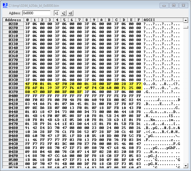
Inserted Code
Finally, I need to route the reset vector to my patch at address 0x3D0: For this I change the original 0x625 at address 0x4 to jump to my code at 0x3d0:
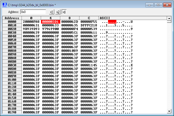
Patched Reset Vector
That's it! Saved the file and program the new bootloader to the board(s). And now all my boards worked without any power-on issues 🙂
Summary
While the new ARM mbed DAPlink bootloader solves the Windows 10 vulnerability, has the problem that it does not deal with power on glitches in a reliable way. I have patched the bootloader with an extra delay loop. The same approach to patch any firmware can be used of course for anything else. All what I need is some assembly programming, a binary editor and a SWD/JTAG programmer.
You can find the patched bootloader binaries on GitHub: https://github.com/ErichStyger/mcuoneclipse/tree/master/OpenSDA/OpenSDA%20V2.2/mbed%20DAPLink%20v244
Happy Patching 🙂
Links
- Patched Bootloader: https://github.com/ErichStyger/mcuoneclipse/tree/master/OpenSDA/OpenSDA%20V2.2/mbed%20DAPLink%20v244
- Update to DAPlink bootloader: https://os.mbed.com/blog/entry/DAPLink-bootloader-update/
- DAPLink releases: https://github.com/mbedmicro/DAPLink/releases
- Recovering and Updating the NXP OpenSDA Bootloader with P&E Multilink and MCUXpresso IDE
- Bricking and Recovering OpenSDA Boards in Windows 8 and 10
- How to Recover the OpenSDA V2.x Bootloader
- New P&E OpenSDA Firmware v114
- Segger J-Link Firmware for OpenSDAv2
- How to enter OpenSDA Bootloader mode: How to put the Kinetis K20 on the tinyK20 Board into Bootloader Mode

Awesome low level stuff. I have a probably silly question about your assembly code, not related to the main issue here, what mode is the assembly code, thumb or ARM and why not load the whole value, why break it into two parts:
“mov r0, #0x600 \n” /* _startup is at 0x625 */
“add r0, #0x25 \n” /* 0x25 because of thumb bit */
I wrote a code snippet to toggle LEDs trying to understand ARM assembly programmers mode, I did:
LDR R1, =0x400ff00c to ‘create a pointer to GPIOA_PTOR.
I really wish it was easy to build the bootloader code from source, I hope your cry will be heard 🙂
LikeLike
Hi David,
thanks! The microcontroller is running thumb instructions, and because of this large constants cannot be directly loaded. One way is to store the constant in the code (at the end of the functio), then load the PC relative address of it adn load it register indirect. To me an easier way is to simply build that constant on the fly as I did (yes, I was lazy). About building the bootloader: I had made that suggestion several times in the past to several ARM engineers. I doubt it will ever happen. Making things easier for ARM internally seems to have a higher priority than making things easier for the ones using ARM. That’s something I see in other places too, btw.
LikeLike
Pingback: Recovering OpenSDA Boards with Windows 10 | MCU on Eclipse
Pingback: tinyK22 Board Rev 1.3 released | MCU on Eclipse