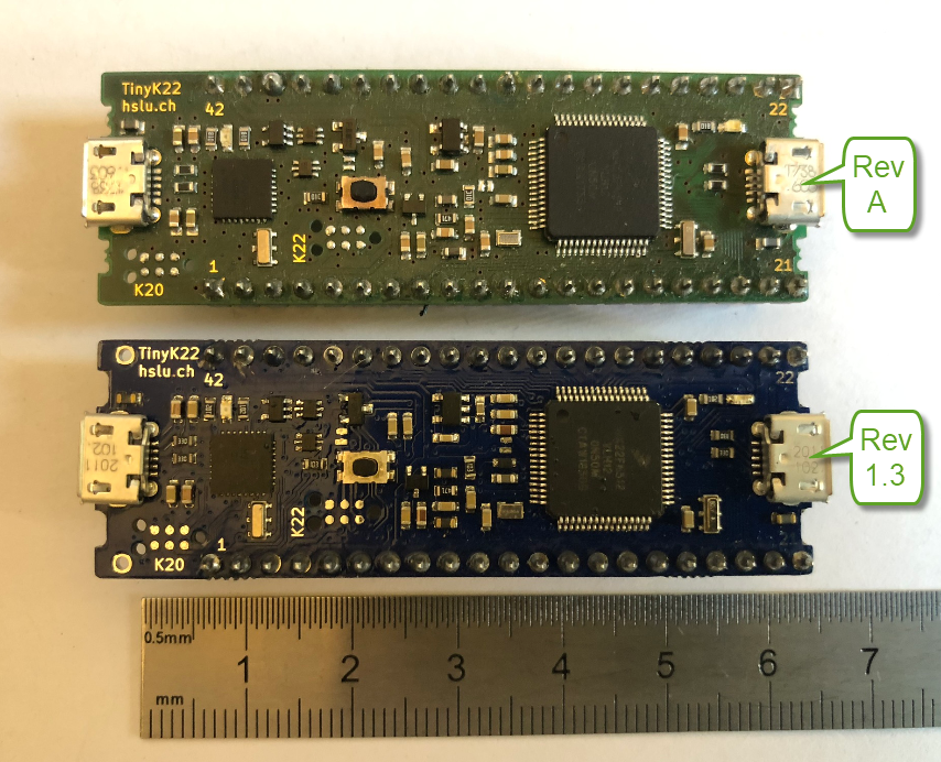
The tinyK22 board is a tiny micro controller board we use at the Lucerne University of Applied Sciences and Arts. It is used in many research project, used in lectures and labs and used in most student projects. Because there was no small and breadboard friendly NXP Kinetis board with a debug interface available, we developed one featuring the NXP K22FN512, named the ‘tinyK22‘. Because of the success and high demand we stated a new large production run and used this to upgrade the board to the new Rev 1.3: you might notice already the color change :-).
tinyK22
The board is a breadboard-friendly, inexpensive and universal ARM Cortex-M4F which can be easily used for a broad range of projects. The board incorporates the OpenSDA circuit and is basically a stripped down version of the popular NXP FRDM-K22F board.

tinyK22 V1.3 Flyer
The board works with GNU Tools for ARM Embedded and can be used out-of-the-box with the NXP MCUXpresso IDE and SDK, or any other custom IDE or tool chain for the K22F512.
Beside of the PCB color change from green to blue, there are several updates with the new V1.3 revision:
First, the SD card holder on the back plus the DC-DC converter for power-hungry cards is populated by default:

tinyK22 PCB Bottom Side
To program and debug the K22, the OpenSDA K20 circuit on the board is used. To save costs and PCB space, both the K20 (debug interface) and the MCU (K22) can be directly programmed with a Tag Connect cable:

Tag Connector
That special debug adapter is from Tag-Connect and the one for ARM Cortex processors. The ‘retaining’ clip is recommended too:
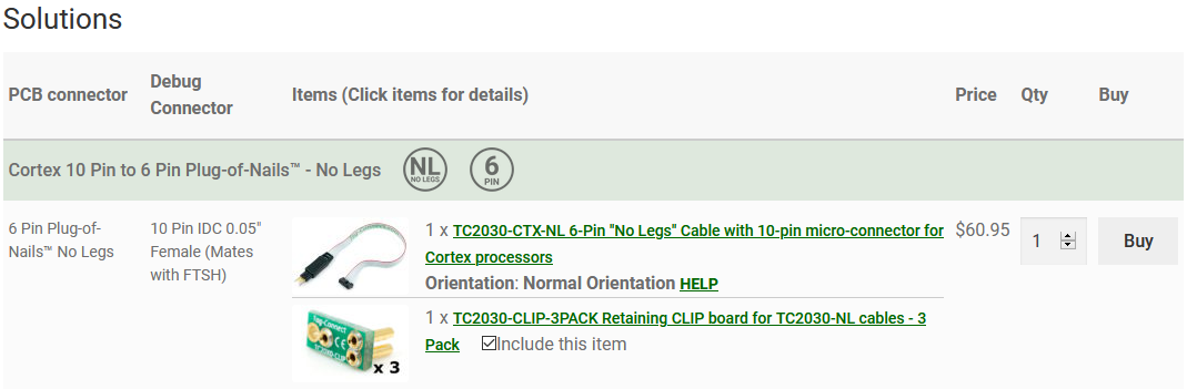
tag connect
With the previous revision, if a student accidentally programmed the K22 with a bad program causing the target to constantly reset, then the OpenSDA circuit was not able to access the CPU (see Adding a Delay to the ARM DAPLink Bootloader on a similar subject). What could happen is that the K20 is forced into bootloader mode. To solve the problem the diode D5 has been added to the reset line:

Diode on reset line
So far the board has been used in-house for research and education. We received frequent requests if we could sell that board. Because we now manufacture and assembly the boards at PCBWay, we published the design and manufacturing files. That way everyone can order boards from there too. The design is available on https://www.pcbway.com/project/shareproject/TinyK22_V1_3.html

tinyK22 on PCBWay
So the new Rev 1.3 boards are produced by PCBWay for us, and you can order yours from there too. Additional information can be found in the links below.
Happy tiny’ing 🙂
Update: the tinyK22 is now featured on Hackster.io: https://www.hackster.io/news/lucerne-university-of-applied-sciences-and-arts-launches-tinyk22-educational-dev-board-v1-3-7be7cebb9d34
Links
- tinyK22 Boards arrived (Rev A)
- First tinyK22 Board with NXP K22FN512 ARM Cortex-M4F
- Documentation and Files on GitHub: https://github.com/ErichStyger/mcuoneclipse/tree/master/tinyK22
- Shared Design on PCBWay: https://www.pcbway.com/project/shareproject/TinyK22_V1_3.html

Nice design. But I’m really hating this K22 so far. I’ve chosen it to redesign our USB / RS232 / LCD / keypad handheld; I’ve struggled with multiple documentation for different variants, hard to find the right info. Even the SDK today seems to be wrong while it’s definitely K22F.
I linked a few PTA pins in parallel to provide a strong 0V for LCD backlight, and couldn’t get debug to work (something to do with PTA4 *during* reset I think, though not documented).
Hopefully things will get better, but this is the worst startup project for more than 15 years!
LikeLike
Hi Ian,
PTA4 is routed by default to the NMI! See https://mcuoneclipse.com/2020/06/09/disabling-nmi-non-maskable-interrupt-pin/. You have to follow that article to disable it.
I hope this helps,
Erich
LikeLike
Thanks, but it’s weirder than that. I have PTA1/2/4/5 linked, they will drive 0V to backlight but LCD not fitted yet. In this setup the debuggers do not connect.
If I hold the pins to VCC the debuggers connect and can program code. That code runs fine without needing to force the pins to VCC.
All those pins are described as pull-up by default after reset.
So something those pins are doing *during* reset is messing up the debuggers.
I’ve tried two debuggers, same result. I see they do toggle SWD clock and data while reset is held low. I think the chip is activating EZPORT for some reason.
If PTA4 is isolated there’s no issue (PCB revision needed).
LikeLike
Did you disable the EZPort already?
LikeLike
Can’t till debugger is running. But I did clear the bit and for one time then debugger connected. But I think (P&E) probably does erase first so the connection did not last long. Only forcing to supply or isolating PTA4 is a consistent fix.
LikeLike
That would mean the P&E probe would affect the flash config settings which I have not observed? I guess you have no J-Link to try out?
LikeLike
I think that’s right, the P&E wipes flex memory on our KE1xF products; I think it always does a chip erase.
LikeLike
Yes, it does. If you don’t re-write a part from your application, that area will be erased. Have you considered reserving memory areas already (https://mcuoneclipse.com/2014/07/13/preserving-memory-ranges-with-eclipse-and-pe-gdb-server/)?
LikeLike
Hi Erich,
Can we purchase the completely assembled tinyk22 from pcbway? I was in the site, looks like they sell just the pub. If we can buy it there, how much are they. Thanks.
Regards,
Anthony
LikeLike
You can buy just the PCB. Or you can use their assembly service.
See github (https://github.com/ErichStyger/mcuoneclipse/blob/master/tinyK22/V1.3) for additional information/screenshots of their assembly service.
Assembly service is around $30 for 5 pieces. Plus the parts and PCB, so should be around $20 per piece or less.
LikeLike
We are PCB manufacturer from Sunking Circuits .We can offer good PCB and PCBA service. You can feel free to contact if you need.Thank you:)
LikeLike
Great, thank you. Can you offer some kind of user collected orders with assembly service?
Basically:
a) users pre-order a number of PCB’s with assembly service and provide a ‘level’ or price point at which the order should be executed
b) other users add to this order until it reaches a certain threshold
c) once the threshold is reached, the orders will be executed
What I’m thinking about is kind of crowd supply with PCB+Assembly service, is that possible?
LikeLike
Pingback: DIY Split-Flap Display | MCU on Eclipse