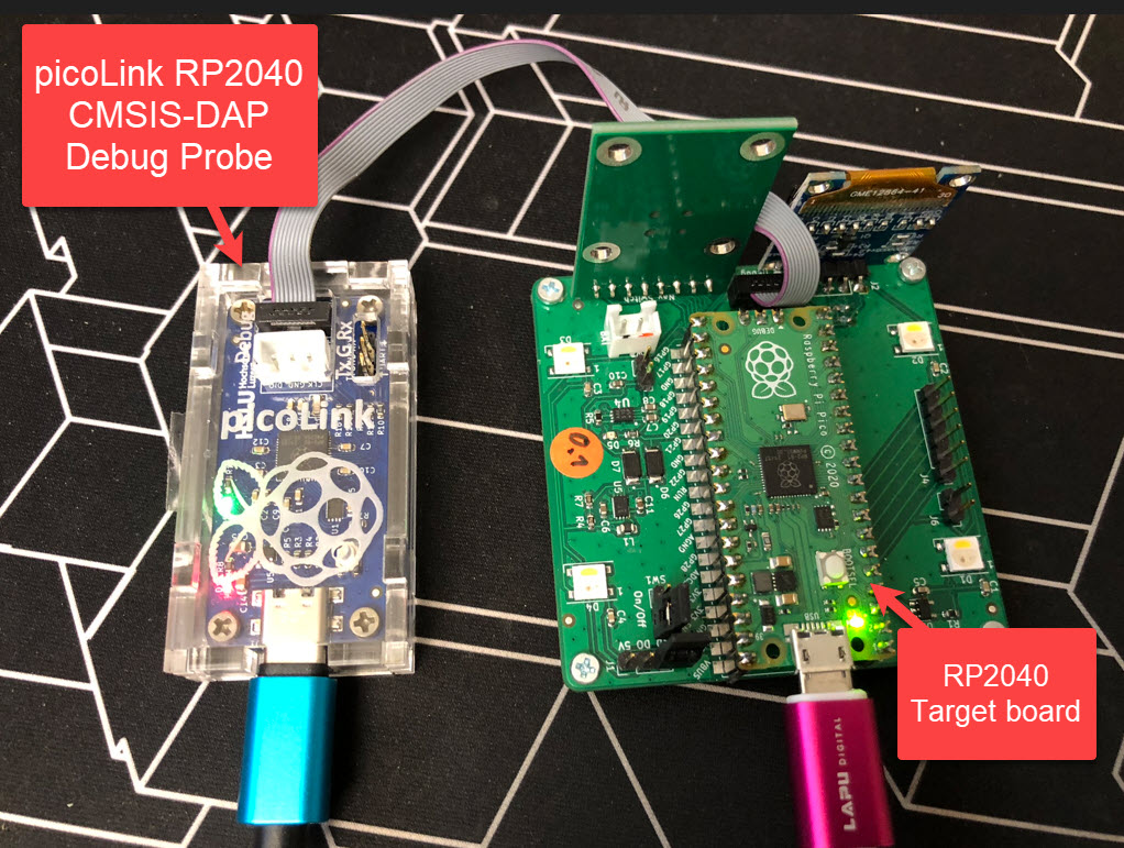
One essential part of embedded development is the ability to debug the target application. The good thing with the Raspberry Pi Pico RP2040 Eco-system is: One can use another RP2040 Pico board as a debug probe to debug other ARM Cortex-M devices.
But instead using a Raspberry Pi Pico board with some wires, why not building a dedicated board? The result is a small, versatile and open source debugging probe which virtually can debug any ARM Cortex-M device as a standard ARM CMSIS-DAP probe:
Outline
As I wrote in “Picoprobe: Using the Raspberry Pi Pico as Debug Probe“, it is easy to use one RP2040 board as a debug probe, and this works great e.g. with a SEGGER J-Link EDU which we use a lot in our classes.

But this requires some bread-boarding and wiring to make a standard debug connector.
All the needed design files are available on GitHub.
PicoProbe PCB Kits
The logical next step is to use a PCB in combination with the Raspberry Pi Pico board, for example the one from Pimoroni which features a standard ARM debug connector, but no target UART option.

Another one is the tiny-picoprobe: This one includes a target UART plus the ability to provide power to the target:

Raspberry Pi Debug Probe
I was really excited when I saw that the Raspberry Pi foundation started to provide a dedicated debug probe based on the RP2040:
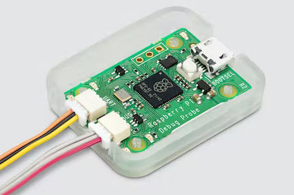
I have not been able to get one of those (yet), but it was not what I had expected:
- It uses different pins according to the schematics information, so the current PicoProbe firmware won’t be compatible.
- Instead of the standard ARM 2×10 pin SWD/JTAG connector, it uses the ‘Raspberry Pi’ ‘non-standard’ 3-pin cable connector.
- It uses micro-USB instead of USB-C. Rather minor, but USB-C cables are getting more and more common.
The ‘official’ probe comes with a nice enclosure, is small and beautiful, plus has buffers on the UART pins, and costs around $15. I think that price point is appropriate for a debug probe.
Yet another Pico Probe Hardware: picoLink
Well, with this I ended up giving ‘yet another’ probe a chance, with the following features:
- Small, around the size of the Pico board itself
- Works with the ‘standard’ PicoProbe firmware
- Standard ARM SWD 10 pin debug header to debug any standard boards
- 3-pin Raspberry Pi debug header to debug Pico and Pico-W boards
- UART connection (VCOM)
- USB-C connector for power and debug the target
- USB-C to debug the RP2040 on the PicoLink (ability to debug the probe firmware itself)

I decided against the function to power the target with 3.3V or 5V: while this sounds nice, it easily can damage the host (without some protection circuit) or damage the target if powering a 3.3V one with 5V. And it would have increased the PCB size and BOM. The BOM costs of the picoLink (see link to GitHub at the end of the article) is ~$5.00 (single quantity, add ~$2 for cables), so around the costs of a Raspberry Pi Pico RP2040 board, but about half of the price for the Raspberry Pi Debug probe
Debugging the picoLink over USB-C Connector
What I really wanted to have on the picoLink board is the ability to debug the RP2040 on it running the debug firmware too. This allows students to develop their own debug firmware. One logical solution would have been to add a debug header on the picoLink itself.
: below I have a SEGGER J-Link EDU debugging the PicoProbe firmware on the PicoLink which is debugging the Pico board I have used in RP2040 with PIO and DMA to address WS2812B LEDs:

💡 Instead using the J-Link EDU Mini, I could have used another picoLink. But as currently I have only one board, I used a J-Link instead.
This means that I don’t need a debug header on the probe itself to debug it if I need it :-).
The USB-C adapter board manages the USB cable and signals, which then get routed through the USB connector to the picoLink board:

Target Debug Headers
The board has two debug connectors: the standard 10pin one plus a 3-pin one:

J5 is an extra debug header, useful to connect to a Pico or Pico-W board having the 3-pin debug interface:

Power Supply, Target UART
Finally, the 3.3V supply from the 5V USB for the probe plus the target UART connection:

The target UART connection provides a VCOM, useful to connect to the UART of another board, here shown using it as a ‘UART-2-USB CDC’ converter with a Raspberry Pi 4:

PCB
The final PCB has a size of 53.3×25.8 mm which is about the size of the Pico board itself (51.3x21mm).

Below a rendering of the PCB:

And here the first populated board:

Enclosure
To protect the hardware and have it ‘nice-looking’, a laser-cut PMMA enclosure has been designed in Inkscape:

Below how it looks:

OpenOCD and Firmware
The debug probe does not only allow debugging the RP2040, but any device supported by OpenOCD.
The probe works with the special RP2040 OpenOCD as outlined in “Picoprobe: Using the Raspberry Pi Pico as Debug Probe” and the PicoProbe firmware: You will need the PicoProbe CMSIS V1.0.1 firmware, because the new ‘official’ Picoprobe uses different pins :-(.
yapicoprobe
Instead of the ‘normal’ PicoProbe firmware,I highly recommend the yapicoprope (‘Yet Another Picoprobe’) which is a fork of the ‘official’ pico probe github.
The firmware is actively developed and comes with tons of really cool features, including support for RTT, CMSIS-DAPv2 with WinUSB, extra CDC logging channel, level shifter support, MSD programming (copy/drag&drop a firmware file to the probe, and it will program the target device), even includes a sigrok probe/logic-analyzer interface, extra status LEDs and more. Plus it is faster (at least as fast as the original PicoProbe). I’m successfully using the rg-1.12 (yapicoprobe-0112-pico-3590ff9.uf2) release with OpenOCD v0.12.
OpenOCD v0.12
I recommend using the newer OpenOCD V0.12 provided by Liviu Ionescu here: https://github.com/xpack-dev-tools/openocd-xpack/releases/tag/v0.12.0-1. And don’t worry: you don’t have to use ‘yet another package manager’: you can simply download the zip file and unpack it. Below are some settings to use OpenOCD v0.12.
Settings for RP2040:
-f interface/cmsis-dap.cfg -f target/rp2040.cfg -c "$_TARGETNAME_0 configure -rtos FreeRTOS" -c "adapter speed 5000"
Or for debugging a NXP Kinetis K22FN512:
-f interface/cmsis-dap.cfg -f target/kx.cfg -c "$_TARGETNAME configure -rtos FreeRTOS"

With this I have full FreeRTOS debugging capabilities in that IDE:

Below the picoLink debugging the NXP FRDM-K22F board:

Summary
The new probe works fine so far, and I’m going to produce more to cover the needs for the labs and ongoing projects. It is supported by the ‘yapicoprobe’ firmware too, and maybe I should consider a new version with all the extra features (LEDs, level shifter, sigrok), but for the moment: all what I need is an inexpensive and powerful open source probe for all the new and upcoming RP2040 projects. The BOM costs are around the normal Pico board, so apart of being a dedicated board and having USB-C, there is not that much of an advantage. But it can be easily extended in a next revision to support more features of the ‘yapicoprobe’, and that will be certainly a plus. It will not replace the J-Links I have in use, but with the challenging availability of J-Link EDU Mini and J-Link EDU on the market it is always good to have choices.
I think these new debug probes based on the RP2040 could be very successful in the market: they are inexpensive, the RP2040 and the RP2040 pico boards are available, and OpenOCD is (slowly) evolving. And a debug firmware like the yapicoprobe is adding useful features, and there are plenty of choices. I will still using commercial or vendor specific debug probes, as they have unique features and benefits. But for a classroom environment, education or hobby projects, an open source CMSIS-DAP debug probe certainly makes sense too.
If you are looking for an inexpensive debug probe, have a look at the MCU-Link which is priced around $13 which works with OpenOCD too.
So what do you think? What kind of debug probe based on the RP2040 do you prefer?
Happy Linking 🙂
And in case you don’t want to use a hardware debug probe: there is a really cool idea to use the second core on the RP2040 for debugging the first core. Of course with limitations, but still a very slick idea.
Links
- Files on GitHub: https://github.com/ErichStyger/mcuoneclipse/tree/master/KiCAD/Projects/PicoLink
- Raspberry Pi Debug Probe: https://www.raspberrypi.com/products/debug-probe/
- Picoprobe: Using the Raspberry Pi Pico as Debug Probe
- OpenOCD: https://openocd.org/
- xPack OpenOCD: https://github.com/xpack-dev-tools/openocd-xpack
- Yet Another PicoProbe firmware: https://github.com/rgrr/yapicoprobe
- MCU-Link debug probe: https://mcuoneclipse.com/2020/11/29/new-mcu-link-debug-probe-from-nxp/

A long time ago, I bought a ‘Black Magic Probe’.. however could never get swd to work with Cortex-M devices from other vendors (ex. Smartfusion2’s Cortex-M3, Microchip Cortex-M7 SAME70).
In general, what needs to be modified in order for the picoprobe to debug non-pico devices. For example, is it just a matter of configuring the command-line parameters so that to openocd points to the desired device file (svd/cfg files).. or something more involved like modifying the picoprobe firmware changes and/or rebuilding openocd?
And if the chip also has ITM’s SWO/TDO (for serial-wire-viewing) can pi-debug-probe + Eclipse/OpenOCD show this trace data? I would think a custom plugin would be needed in Eclipse, no?
LikeLike
Hi Ben,
I had very similar results with the Black Magic Debug probe (see https://mcuoneclipse.com/2019/06/23/black-magic-open-source-debug-probe-for-arm-with-eclipse-and-gdb/). I think I still might have it around somewhere, but stopped using it about 3 years ago. It only worked with a very few and limited set of targets. Not sure what the state these days would be.
As for using devices with OpenOCD: yes, it is pretty much a thing of having the correct configuration script for a given device and board. OpenOCD itself needs to have some knowledge too about the probe and the features used by the device, that’s why OpenOCD sometimes needs a specific build or feature set, which does not make it easy to use. Things are getting better with the evolution of CMSIS-DAP protocol, as it defines a standard set of commands between the host and the probe, making things hopefully easier in the future, to avoid that ‘device and board script hell’ in OpenOCD. On the plus side, if you build OpenOCD from the sources, the script approach is really flexible.
As for OpenOCD and the PicoProbe firmware (or similar ones): with OpenOCD v0.12 and the CMSIS-DAP this can work out of the box, if you have a script file for your board/device. Things get difficult if the device has special memory areas and memory/flash programming needs, or if you are dealing with special fuses or security settings. Naturally, OpenOCD supports the ‘common’ parts, and with ‘special’ parts you might be out of luck. Here I recommend to stick with a commercial probe and commercial/vendor tools.
SWO is yet another topic: CMSIS-DAP had added it a while ago, but debug servers and IDEs only started recently supporting it. This is a topic I might write about in a future article, if time permits. Most debug servers provide a SWO channel through a telnet port, which then can be used by a telnet client or if supported in the IDE. So yes, some kind of ‘plugin’ is required, or at least a telnet connection (which for example works with RTT too, see https://mcuoneclipse.com/2015/07/07/using-segger-real-time-terminal-rtt-with-eclipse/ )
LikeLike
Pingback: The open source picoLink: Raspberry Pi RP2040 CMSIS-DAP debug probe #PiDay @McuOnEclipse @Raspberry_Pi « Adafruit Industries – Makers, hackers, artists, designers and engineers!
Hello Erich,
thanks for mentioning my efforts. Your article is as always very inspiring.
Question: is there any source where one can buy your probe hardware ready assembled?
LikeLiked by 1 person
You are welcome!
I was thinking about having PCBWay assemble them, but have not prepared the BOM or files for them. Then everyone can order from them, assembled. Do you feel there will be a lot of demand for such a thing?
LikeLike
Hi,
first of all thanks for sharing your project as description. Wrt to your question it certainly depends on your definition of “a lot”. As usual price point will be a discriminator but given that there is a general tendency to support well made open source hardware I’d imagine an audience to be there.
LikeLike
Hi Marcus,
thanks, that for sure gives a perspective. As a side note: the project is not only shared as description: you can find all the design files on GitHub: https://github.com/ErichStyger/mcuoneclipse/tree/master/KiCAD/Projects/PicoLink
LikeLike
Hello Erich,
just want to mention, that yapicoprobe made some progress in the meantime. Most important is SystemView support via USB-NCM.
LikeLike
Hi Hardy,
Interesting. How would SEGGER SystemView connect to that NCM port?
LikeLike
Short answer: “Target/Recorder Configuration/IP/Connection”. So actually nothing special.
LikeLike
Longer answer: some network / adapter setup has to be done. See Readme. I have some problems under Windows 10 that the manually setup driver is lost from time to time. Under linux after initial setup no problems.
LikeLike
Hi Erich,
I’ve been doing a lot recently with writing C modules for MicroPython for the RP2040. From looking at older posts, it seems there has been some progress importing the MicroPython source tree into Eclipse from the make file.
This would be a very interesting as there is no IDE for this application–everything is done via the command line. Being able to develop AND debug would be really useful using an OpenOCD tool like JLink or PicoProbe.
I think MicroPython is the wave of the future for the embedded world. It continues to improve and can even work with FreeRTOS. (The ESP32 version of MicroPython uses FreeRTOS.)
https://github.com/micropython/micropython
https://github.com/micropython/micropython/issues/5178
Cheers,
Brad
LikeLike
Hi Brad,
I see MicroPython growing especially at the entry or non-professional level. It is great to get something started, or adding some kind of user scripting/configuration level to the user (good example is to use a camera module/application, which includes a MicroPython engine for the user).
As always, it depends on what you want and need to do.
LikeLike
Hi Erich,
MicroPython is being used in the professional sector as well. I’ve already implemented it into several industrial IoT and automotive applications. Anything you do in C/C++ plus OS you can do in MicroPython, but is so much easier and faster. And my clients can maintain the software. MPy may be slower, but in most cases, it’s “fast enough”. But there are many ways to achieve near C speed and determinism.
Here’s a good article on using MPy in satellites. https://ieeexplore.ieee.org/document/10115576
An Eclipse IDE for customizing and debugging MPy would be a valuable tool.
LikeLike
Hi Brad,
have you used it in any low power applications?
LikeLike
Yes. All power modes are supported, depending on the processor (machine class). And it has methods to read the wake up source, e.g. RTC, external pin, or POR.
I wanted to quickly mention CircuitPython from Adafruit. It is a fork of the MicroPython project. I would not consider this professional grade but is an excellent tool for education and hobbyists.
LikeLike
I ask because we wanted to use Python on an embedded low power (low power control loop application, running on battery). Yes, Python supported low power modes as you descried, and we used it to the max. But because of huge overhead of Python compared to C, the application implemented in Python consumed ~80 times more compared to the same implemented in C, so we abandoned the idea using Python for this kind of embedded application. We tried have implemented most things in C and call it from Python, but it was still a factor of 10 because of the overhead of Python, and the code and data size needed was another roadblock too.
To us the conclusion was: if you have excess energy and code/data space available and the application does not need to be efficient, then Python can be a choice, e.g. we are using it for example on desktop machine for some tasks. The Adafruit Micropython is what we are using in educational projects too, there it is a great fit.
LikeLike
I compared two IoT designs, one with C and one with Micropython. Power and battery life are essentially the same. The system spends most of it’s time in hibernation, so this is not surprising.
LikeLike
If it is not doing anything in Python, then such a result is expected. I’m more concerned where the Python is really doing something on the target. You can find an interesting overview in the paper of Pereira, R. et al. (2017) ‘Energy efficiency across programming languages: how do energy, time, and memory relate’. In confirms what we saw with a vision/camera project, where Python was used to calculate things on the device: we completely switched from Python to C because the energy used by the Python system used more than 10 times the energy than running the system in normal C. I think Python can be a good addition to a system offering a ‘user scripting way’, but here again I’m concerned about possible security issues (which applies to any scripting interface).
LikeLike
Take a look at this YouTube video. I’ve used the “Viper” method to implement a touch pad algorithm that is almost as fast as C.
LikeLike
Oops. Here’s the link https://www.youtube.com/watch?v=hHec4qL00x0&t=1624s
LikeLike
Forgot to send the link
LikeLike