I love the WS2812B (aka SK6812) addressable LEDs: they are inexpensive and available in different packages. I have used them in different projects, including the MetaClockClock one. I used the NXP Kinetis for these projects, but because they are not available any more, for a new project we had to choose a new microcontroller, with the Raspberry Pi Pico RP2040 as the winner.
Outline
In that project, the MCU needs to drive a total of 1024 SK6812 RGB LEDs. To keep the refresh rate reasonable, the LEDs are organized in 8 stripes with 128 LEDs each. The Kinetis K22 or K64 with DMA can easily produce the needed 800 kHz protocol using DMA, see Tutorial: Adafruit WS2812B NeoPixels with the Freescale FRDM-K64F Board – Part 1: Hardware.
I have used the LPC804 for a similar thing using the PLU, but that is only for one single channel, see Adding RGBW Wings and Enclosure to a Debug Probe. But that was for single-lane only.
The Raspberry Pi RP2040 MCU is available and inexpensive (~$1). It has a dual core Cortex-M0+ @120 MHz with 264 KByte of internal RAM. It is not the most powerful MCU on the market, but has an excellent tool and software ecosystem, making it easy for students to use in many projects. It has a wireless option (WiFi, Bluetooth and BLE) which is ‘compatible’ with the Pico board, and the Pico board costs less than $5.
An interesting feature of the RP2040 MCU is the PIO: programmable I/O ‘co-processors’ which can be used to implement custom protocols, for example the 800 kHz bit-stream needed to address the WS2812B/SK6812B LEDs.
💡 The Raspberry Pi SDK 1.5 comes with a PIO example for WS2812B which I have used as base example for this implementation.
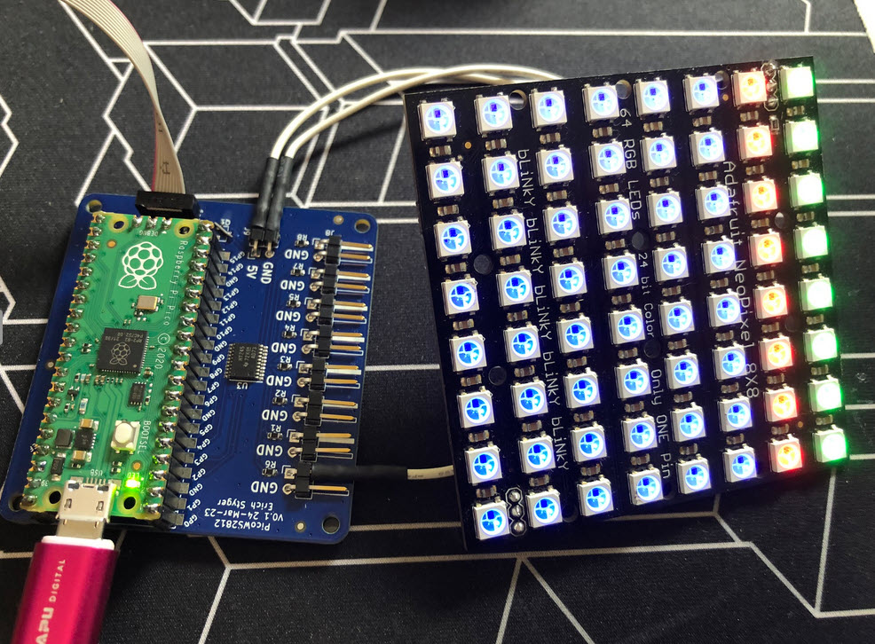
To develop the software, as simple test board with 8 channels using the Raspberry Pi Pico RP2040 has been created, for both the Pico and Pico-W boards:

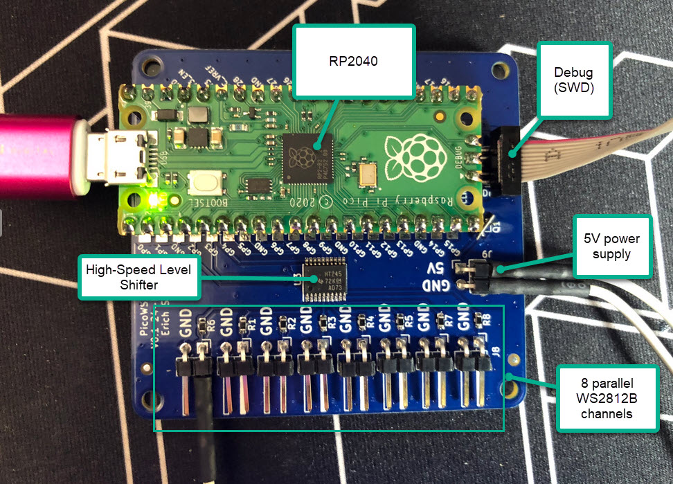
The board uses the GPIO2 to GPIO9 to drive the LEDs:

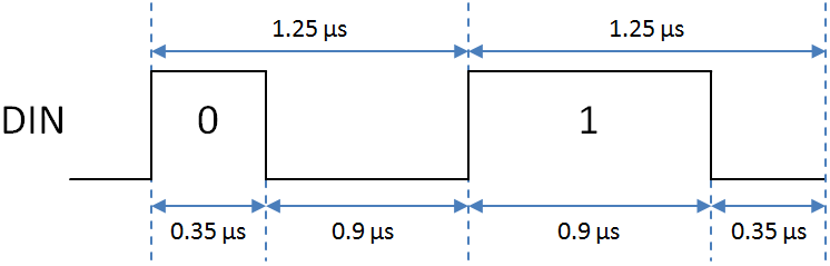
The protocol to the LEDs is a stream of bits with a frequency of 800 kHz, encoding the 0 and 1 bits. Because the LEDs need a 5V logic level and the RP2040 uses 3.3V, a high speed 74HCT245 level shifter is used:

8 bits for each color, in G->R->B order, for which we will use the RP2040 PIO hardware with DMA.
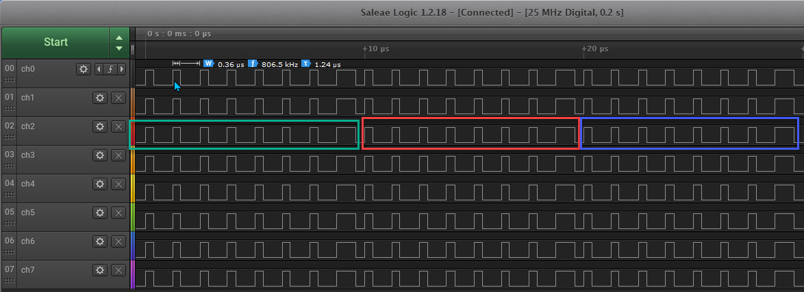
The software supports both single RGB or RGBW LEDs, or multi-parallel lanes up to 8 channels. Below the output of the green, red and blue bits, each color using the value 0x01:
Below a capture with 8 channels using RGBW SK6812/WS2812B: here the white part is after the green-red-blue:
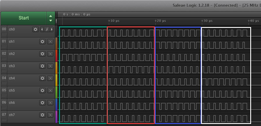
At the end of the transfer, there has to be a 400 us time with all signals LOW to ‘latch’ in the data into the LEDs.
The number of ‘colors’ (3 or 4), the number of lanes and number of LEDs in each lane is configured in NeoConfig.h:
#define NEOC_NOF_COLORS        (4)  /* number of colors: 3 for RGB, 4 for RGBW */
#define NEOC_NOF_LANES         (8) /* number of lanes (and pins) to be used */
#define NEOC_NOF_LEDS_IN_LANE   (8) /* number of LEDs in a lane */
The full project and example code is available on GitHub (CMake, Eclipse, Visual Studio Code), see links at the end of this article.
PIO: Programmable I/O
The PIO is a kind of programmable co-processor on the RP2040. There are two identical PIO blocks on the Raspberry Pi RP2040:
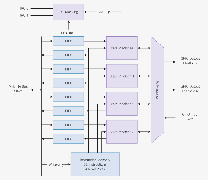
Each PIO has 4 state machines with FIFOs which can execute instructions, using and manipulate different GPIO pins. The PIO comes with its own interrupts and can be used with DMA (Direct Memory Access). The PIO hardware is ideal to implement your own protocol, for example a CAN protocol or ‘bit-banged-Ethernet‘.
Each state machine uses shift registers with two scratch registers (X and Y):
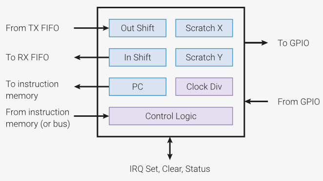
The PIO understands nine instructions (with various arguments):
in(): shift bits into the input shift register (ISR)out(): shift bits out of the output shift register (OSR)push(): push content of ISR into RX FIFOpull(): load a 32bit word from the TX FIFO into the OSRmov(): Copy data from source to destinationirq(): set or clear interrupt flagswait(): wait until condition is metjmp(): Jump to a labelset(): write immediate value to destination
Each instructions only takes a single cycle, and using the ClockDiv and extra delays the speed of execution can be affected.
A dedicated PIO assembler supports pseudo instructions, things like nop or special directives like .wrap with labels.
PIO Assembler
To simplify coding the PIO, the Raspberry Pi SDK comes with a special assembler, translating the assembly code into C source and header files which can be integrated into the application. In a Cmake based build, I can call pico_generate_pio_header:
# generate PIO header "ws2812.pio.h" inside the src directory
pico_generate_pio_header(${PROJECT_NAME} ${CMAKE_CURRENT_LIST_DIR}/ws2812.pio)
This takes the ws2812.pio assembler program and creates the ws2812.pio.h header file I can use in my C/C++ application:

PIO with Single-Lane LEDs
The simplest way is to use a single LED stripe or lane. For this every pixel color information is stored in a 32bit value:
static uint32_t transmitBuf[NEO_NOF_LEDS_IN_LANE];
The bits are stored as 0xgg-rr-bb-ww (RGBW) or 0xgg-rr-bb-00 (RGB), which makes it easy to set the color of an individual pixel:
uint8_t NEO_SetPixelRGB(NEO_PixelIdxT pos, uint8_t red, uint8_t green, uint8_t blue) {
  transmitBuf[pos] = ((uint32_t)(green)<<24) | ((uint32_t)(red)<<16) | ((uint32_t)(blue)<<8);
  return ERR_OK;
}

uint8_t NEO_SetPixelWRGB(NEO_PixelIdxT pos, uint8_t white, uint8_t red, uint8_t green, uint8_t blue) {
  transmitBuf[pos] = ((uint32_t)(green)<<24) | ((uint32_t)(red)<< 16) | ((uint32_t)(blue)<<8) | (uint32_t)(white);
  return ERR_OK;
}
We use here 32bit of data for both RGB and RGBW case, because we will read a 32bit value into the PIO. Below is the PIO assembly program. Each instruction takes a single cycle, which can be extended by the number following in [..]. After the comment starting with ‘;’ I have noted the total number of cycles for each line:
.wrap_target
bitloop:
    out x, 1       side 0 [2]   ; [3] Side-set still takes place when instruction stalls
    jmp !x do_zero side 1 [2]   ; [2] Branch on the bit we shifted out. Positive pulse
do_one:
    jmp  bitloop   side 1 [3]   ; [5] Continue driving high, for a long pulse
do_zero:
    nop            side 0 [3]   ; [5] Or drive low, for a short pulse
.wrap
The out x,1 instruction emits one bit after each other, followed by jumps and delays to build a 0 or 1 bit. For each bit the PIO requires 3+2+5+5 cycles, so a total of 10 cycles:
.define public NOF_CYCLES_FOR_1_BIT (3+2+5)
which gets translated into the ws2812.pio.h header file:
#define ws2812_NOF_CYCLES_FOR_1_BIT 10
Finally, the PIO needs to be initialized:
static inline void ws2812_program_init(PIO pio, uint sm, uint offset, uint pin, float freq, bool rgbw) {
  pio_gpio_init(pio, pin); /* initialize pin for usage with the PIO */
  pio_sm_set_consecutive_pindirs(pio, sm, pin, 1, true); /* set pin direction. 1: number of pins. true: as output pin */
  pio_sm_config c = ws2812_program_get_default_config(offset); /* get default configuration */
  sm_config_set_sideset_pins(&c, pin); /* use pin as side set */
  sm_config_set_out_shift(&c, false, true, rgbw ? 32 : 24); /* false: shift left. true: auto-pull. Number of bits based on rgb or rgbw */
  sm_config_set_fifo_join(&c, PIO_FIFO_JOIN_TX); /* combine both FIFOs as TX_FIFO, so we have a bigger FIFO */
  /* calculate state machine clocking based on protocol needs */
  float div = clock_get_hz(clk_sys) / (freq * ws2812_NOF_CYCLES_FOR_1_BIT);
  sm_config_set_clkdiv(&c, div);
  /* initialize PIO and start it */
  pio_sm_init(pio, sm, offset, &c);
  pio_sm_set_enabled(pio, sm, true); /* true: enable pio */
}
This initializes the pin to be used, configures the shifting and clocking to output the bit stream. Finally the PIO needs to be initialized with it:
void WS2812_Init(void) {
  PIO pio = pio0; /* the PIO used */
  WS2812_sm = 0; /* state machine used */
  uint offset = pio_add_program(pio, &ws2812_parallel_program); /* add program and get offset */
  ws2812_parallel_program_init(pio, WS2812_sm, offset, NEOC_PIN_START, NEOC_NOF_LANES, 800000); /* initialize it for 800 kHz */
}
That’s it. Now we can send one pixel after each other using the PIO:
int WS2812_Transfer(uint32_t address, size_t nofBytes) {
  uint32_t *p = (uint32_t*)address;
  for(int i=0; i<nofBytes/sizeof(uint32_t); i++) { /* without DMA: writing one after each other */
    pio_sm_put_blocking(pio0, WS2812_sm, *p);
    p++;
  }
  vTaskDelay(pdMS_TO_TICKS(1)); /* latch */
  return 0; /* ok */
}
Note that we do not use DMA here (yet): this is something we look into it later.
PIO with Parallel-Lane LEDs
So far we have used a single lane of LEDs. To unleash the power of the PIO we can send 8 bits at once, building up to 8 parallel lanes of LEDs which is suitable for most WS2812B applications.
For this, we use a different PIO program, which shifts out 8bits in each iteration:
.wrap_target
    mov x, null           ; [1] clear X scratch register
    out x, 8              ; [1] copy 8bits from OSR to X
    mov pins, !null [2]   ; [3] T1: set all pins HIGH (!NULL)
    mov pins, x     [3]   ; [4] T2: pulse width: keep pins high (for 1 bits) or pull low (for 0 bits)
    mov pins, null        ; [1] T3: pull all pins low
 .wrap
This PIO program shifts out 8 bits of the pixel data, building the necessary waveform using 8 GPIO output pins. Because we load the FIFO with 32bits and shift it out in 8-bit chunks, we need to organize the bit data in memory a bit different than in the single-lane case.
The buffer gets changed to
static uint32_t transmitBuf[NEO_NOF_LEDS_IN_LANE*NEO_NOF_BITS_PIXEL/4]; /* we put 4x8 bits into a 32bit word */
Because we shift out the green bits of all lanes out first, the memory layout changes too. Below the bits in memory for the first 8 parallel pixels:
transmitBuf[0]: 4x 8bit:    gg gg gg gg gg
transmitBuf[1]: 4x 8bit:    gg gg gg gg gg
transmitBuf[2]: 4x 8bit:    rr rr rr rr rr
transmitBuf[3]: 4x 8bit:    rr rr rr rr rr
transmitBuf[4]: 4x 8bit:    bb bb bb bb bb
transmitBuf[5]: 4x 8bit:    bb bb bb bb bb
transmitBuf[6]: 4x 8bit:    ww ww ww ww ww
transmitBuf[7]: 4x 8bit:    ww ww ww ww ww
...
In case of RGB (no W), the next pixel follows at transmitBuf[6], so no bits are ‘wasted’ as in the case of single-lane RGB. But this complicates setting the color of a single pixel (see source code on Github for details).
Otherwise, things are pretty much the same as for the single lane case. Sending 8 pixels in parallel needs 8 PIO cycles:
uint32_t *p = (uint32_t*)address;
for(int i=0; i<nofBytes/sizeof(uint32_t); i++) { /* without DMA: writing one after each other */
  pio_sm_put_blocking(pio0, WS2812_sm, *p);
  p++;
}
vTaskDelay(pdMS_TO_TICKS(1)); /* latch */
Using that approach, it needs less than 4 ms to write 1024 RGB LEDs:
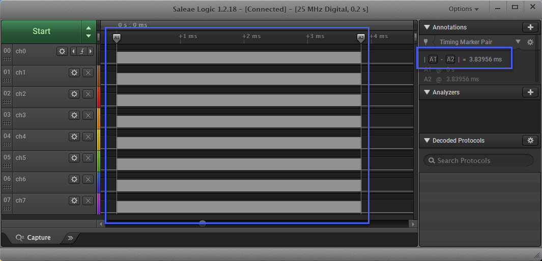
The issue is: during this time the MCU (well, at least one core) is busy and cannot do anything else.
DMA
Putting out one pixel after each other is OK for smaller LED installations. But for larger number of LEDs you want to use DMA (Direct Memory Access). Using DMA, the data transfer happens in the background, freeing up the CPU doing other things.
The concept is the following:
- A semaphore blocks in case a previous transfer is going on.
- After the semaphore is free, it gets acquired.
- The DMA transfer gets started and feeds the PIO with all the data.
- At the end of transfer, an interrupt gets raised, which releases the semaphore after the latching time for the next iteration.
First, we configure the DMA for the given PIO and state machine:
static void dma_init(PIO pio, unsigned int sm) {
  dma_claim_mask(DMA_CHANNEL_MASK); /* check that the DMA channel we want is available */
  dma_channel_config channel_config = dma_channel_get_default_config(DMA_CHANNEL); /* get default configuration */
  channel_config_set_dreq(&channel_config, pio_get_dreq(pio, sm, true)); /* configure data request. true: sending data to the PIO state machine */
  channel_config_set_transfer_data_size(&channel_config, DMA_SIZE_32); /* data transfer size is 32 bits */
  channel_config_set_read_increment(&channel_config, true); /* each read of the data will increase the read pointer */
  dma_channel_configure(DMA_CHANNEL,
                        &channel_config,
                        &pio->txf[sm], /* write address: write to PIO FIFO */
                        NULL, /* don't provide a read address yet */
                    #if NEOC_NOF_LANES>1
                        NEOC_NOF_LEDS_IN_LANE*2*NEOC_NOF_COLORS, /* number of transfers */
                    #else
                        NEOC_NOF_LEDS_IN_LANE, /* number of transfers */
                    #endif
                        false); /* don't start yet */
  irq_set_exclusive_handler(DMA_IRQ_0, dma_complete_handler); /* after DMA all data, raise an interrupt */
  dma_channel_set_irq0_enabled(DMA_CHANNEL, true); /* map DMA channel to interrupt */
  irq_set_enabled(DMA_IRQ_0, true); /* enable interrupt */
}
Notice that DMA configuration above is the same for 1-lane and n-lane configuration: the DMA writes 32bit in both cases, only the number of total transfers is different, based on the amount of LEDS used.
The DMA channels writes to the PIO FIFO, with the source register not set yet: because we will start and triggering the DMA sequence with setting the read register to a non-zero value later on.
&pio->txf[sm], /* write address: write to PIO FIFO */
NULL, /* don't provide a read address yet */
The above configuration uses an interrupt handler which gets called at the end of the full DMA transfer:
void dma_complete_handler(void) {
  if (dma_hw->ints0 & DMA_CHANNEL_MASK) { /* are we called for our DMA channel? */
    dma_hw->ints0 = DMA_CHANNEL_MASK; /* clear IRQ */
    if (reset_delay_alarm_id!=0) { /* safety check: is there somehow an alarm already running? */
      cancel_alarm(reset_delay_alarm_id); /* cancel it */
    }
    /* setup alarm to wait for the required latch-in time for the LES at the end of the transfer */
    reset_delay_alarm_id = add_alarm_in_us(RESET_TIME_US, reset_delay_complete, NULL, true);
  }
}
Finally, the code for the alarm which gets raised 400 us after the last bit transmitted:
#define RESET_TIME_US       (60)  /* RES time, specification says it needs at least 50 us. Need to pause bit stream for this time at the end to latch the values into the LED */

static struct semaphore reset_delay_complete_sem; /* semaphore used to make a delay at the end of the transfer. Posted when it is safe to output a new set of values */
static alarm_id_t reset_delay_alarm_id; /*  alarm id handle for handling delay */

static int64_t reset_delay_complete(alarm_id_t id, void *user_data) {
  reset_delay_alarm_id = 0; /* reset alarm id */
  sem_release(&reset_delay_complete_sem); /* release semaphore */
  return 0; /* no repeat */
}
The alarm is responsible to reset the alarm ID and releasing the blocking semaphore, so a new transfer can start.
Final Transfer Code
Now we are ready to bring everything together:
int WS2812_Transfer(uint32_t address, size_t nofBytes) {
#if NEOC_NOF_LANES>1
  #if NEOC_USE_DMA
    sem_acquire_blocking(&reset_delay_complete_sem); /* get semaphore */
    dma_channel_set_read_addr(DMA_CHANNEL, (void*)address, true); /* trigger DMA transfer */
  #else
    uint32_t *p = (uint32_t*)address;
    for(int i=0; i<nofBytes/sizeof(uint32_t); i++) { /* without DMA: writing one after each other */
      pio_sm_put_blocking(pio0, WS2812_sm, *p);
      p++;
    }
    vTaskDelay(pdMS_TO_TICKS(1)); /* latch */
  #endif
#else /* single lane */
  #if NEOC_USE_DMA
    sem_acquire_blocking(&reset_delay_complete_sem); /* get semaphore */
    dma_channel_set_read_addr(DMA_CHANNEL, (void*)address, true); /* trigger DMA transfer */
  #else
    for(int i=0; i<NEOC_NOF_LEDS_IN_LANE; i++) { /* without DMA: writing one after each other */
      pio_sm_put_blocking(NEO_GetPixel32bitForPIO(NEOC_LANE_START, i));
    }
    vTaskDelay(pdMS_TO_TICKS(1)); /* latch */
  #endif
#endif
  return 0; /* ok */
}
With this, we can use the PIO for single and multiple (2-8) lanes, both for RGB and RGBW WS2812B/SK6812 LEDs, with and without DMA :-).
Summary
The PIO on the Raspberry Pi RP2040 is a very useful and interesting hardware, for example to handle the WS2812B protocol without direct CPU involvement. If combined with DMA, I can efficiently handle large amount of data in the background, and the MCU can work on other things in parallel.
Using PIO and DMA could be daunting at the beginning, but it is really easy once get used to it. And I hope this article and code on GitHub gives you a good start using the RP2040 with PIO and DMA for your own project.
Happy LEDing 🙂
PS: This LED cube project is still work in progress, so check out future articles or the state of the project on GitHub.
Links
- Example project on GitHub: https://github.com/ErichStyger/mcuoneclipse/tree/master/Examples/RaspberryPiPico/pico_LedCube
- KiCAD project: https://github.com/ErichStyger/mcuoneclipse/tree/master/KiCAD/Projects/PicoWS2812B
- Rasperry Pi RP204 SDK: https://datasheets.raspberrypi.com/pico/raspberry-pi-pico-c-sdk.pdf
- Round MetaClockClock
- MetaClockClock Build Instructions
- Tutorial: Adafruit WS2812B NeoPixels with the Freescale FRDM-K64F Board – Part 5: DMA

RP2040 PIO Emulator
https://rp2040pio-docs.readthedocs.io/en/latest/pio-programs.html
LikeLike
There is as well this one: https://github.com/NathanY3G/rp2040-pio-emulator
LikeLike
Pingback: RP2040 with PIO and DMA to address WS2812B LEDs #PiDay #NeoPixels @Raspberry_Pi @McuOnEclipse « Adafruit Industries – Makers, hackers, artists, designers and engineers!
Do you have issues with power distribution via this board? LED power consumption varies, but a conservative estimate seems to be about 0.1 Watt per LED, which is 100 Watts for 1000 LEDs. At 5Vs that’s 20 Amps going through your PCB traces.
LikeLike
That board can drive a smaller number of LEDs, depending on type and power consumption (up to 500 mA).
For more LEDs, I use dedicated 5V power supplies.
LikeLike
Actually I see the board doesn’t drive the power on the LEDs, just ground and data.
LikeLike
The board has a 5V pin to provide power from the 5V USB, up to 500 mA. That’s enough to drive a certain number of LEDs, depending on the LED type and LED power consumption. For more LEDs, you need to power them with a dedicated power supply.
LikeLike