During Embedded World 2017 in Nürnberg I was lucky to get a handful LPC800-DIP boards. To get all students who were lucky to get one, here is a tutorial to make that very exciting ‘blinky’ application on that board:
Blinky on the NXP LPC800-DIP
MCUXpresso IDE Series
This article is part of a series to get up to speed using the new NXP MCUXpresso IDE. Published so far are:
- MCUXpresso IDE: Unified Eclipse IDE for NXPs ARM Cortex-M Microcontrollers
- MCUXpresso IDE: S-Record, Intel Hex and Binary Files
- MCUXpresso IDE: Adding the Eclipse Marketplace Client
- MCUXpresso IDE: Importing Kinetis Design Studio Projects
- MCUXpresso IDE: Installing Processor Expert into Eclipse Neon
- MCUXpresso IDE: Terminate and Disconnect a Debug Session
- MCUXpresso IDE: Blinky the NXP LPC800-DIP Board
Outline
This article shows to run a first ‘blinky’ (toggling LEDs on the board) on the LPC800-DIP board using Eclipse (MCUXpresso IDE) and the NXP LPCOpen library.
LPC800-DIP Board
You need
- LPC800-DIP board or any other LPC8xx board, in that case you will need to change the LED pins in the source code
- MCUXpresso IDE V10.0.0 b344
- Micro USB cable
- SWD/JTAG debug probe like the LPC-Link2
💡 The LPC800-DIP board does not contain a debug interface, but the USB-2-UART bridge which can be used with the FlashMagic (by Embedded Systems Academy) tool to program binaries. As I want to debug my application, I’m not using this tool in this article.
💡 A link to all the project and source files is provided at the end of the article
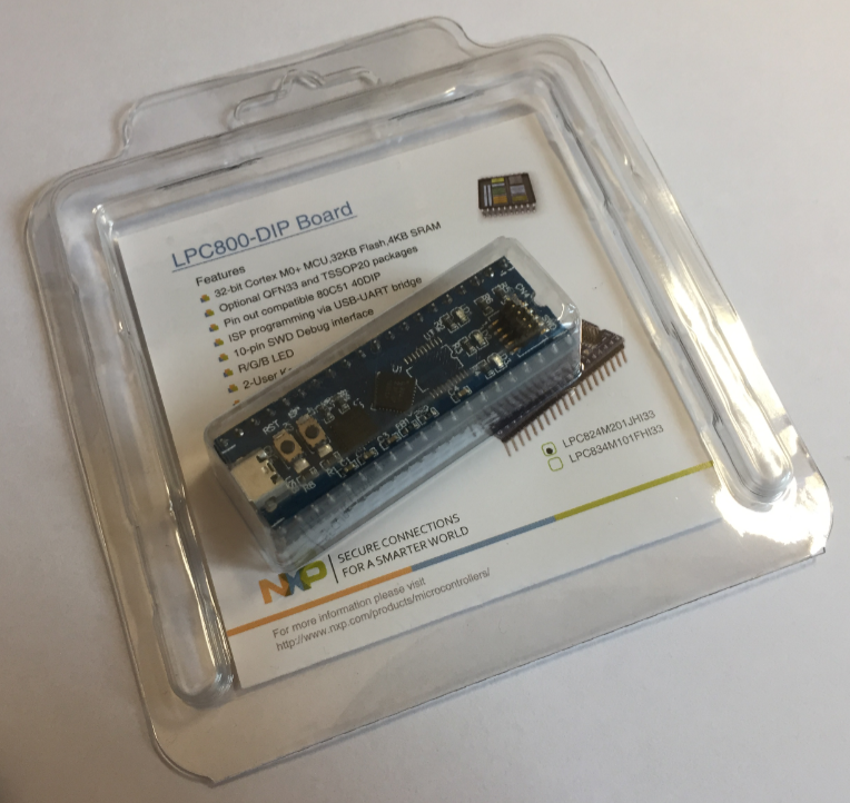
LPC800-DIP Board
The LPC800-DIP board is a tiny board with the NXP LPC824 microcontroller on it:
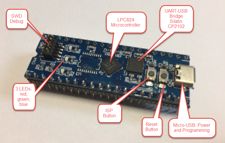
LPC800-DIP Board Details
It has the LPC824M201JHI33 on it (32 bit Cortex-M0+, 32 KByte Flash, 4 KB RAM) in breadboard friendly pin out. The microcontroller can be programmed using SWD or through the Silabs CP2102 UART-USB bridge: with pressing the ISP button I can program the device through the USB connection to the host and the FlashMagic utility.
SDK: LPC Board and LPC Chip Projects
To start with the board, I need a software library or SDK. For the LPC800 NXP provides the LPCOpen library. That library already is installed with the MCUXpresso IDE:
LPCOpen Libraries
Alternatively, I can find them here: http://www.nxp.com/products/software-and-tools/software-development-tools/software-tools/lpcopen-libraries-and-examples/lpcopen-software-development-platform-lpc8xx:LPCOPEN-SOFTWARE-FOR-LPC8XX
I import the library project into my workspace using the ‘Import project(s) from file system…’ from the Quickstart panel in the MCUXpresso IDE:
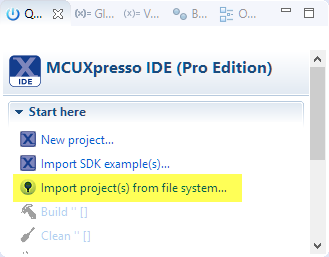
Import projects
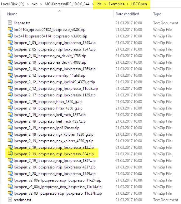
Then browse for the LPCOpen archive file:
C:\nxp\MCUXpressoIDE_10.0.0_344\ide\Examples\LPCOpen\lpcopen_2_19_lpcxpresso_nxp_lpcxpresso_824.zip
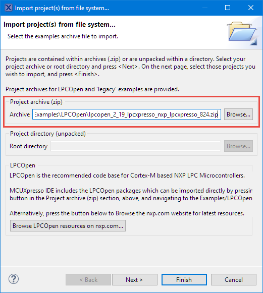
Select LPCOpen Archive
Press Next. I get offered a selection of projects to import. I need the chip library which I select:
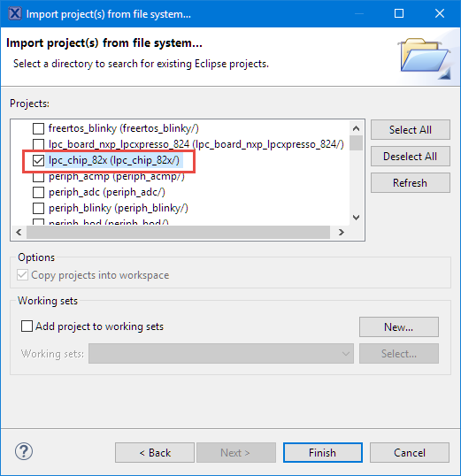
LPC Chip Library
The ‘chip’ library as the name indicates supports the given chip. I could as well import the board library (but that one would be for that board) or the example projects. For my blinky project all what I need is the chip library and I will do my ‘board support’ for the LEDs.
Press Finish, and the chip library shows up in the workspace:
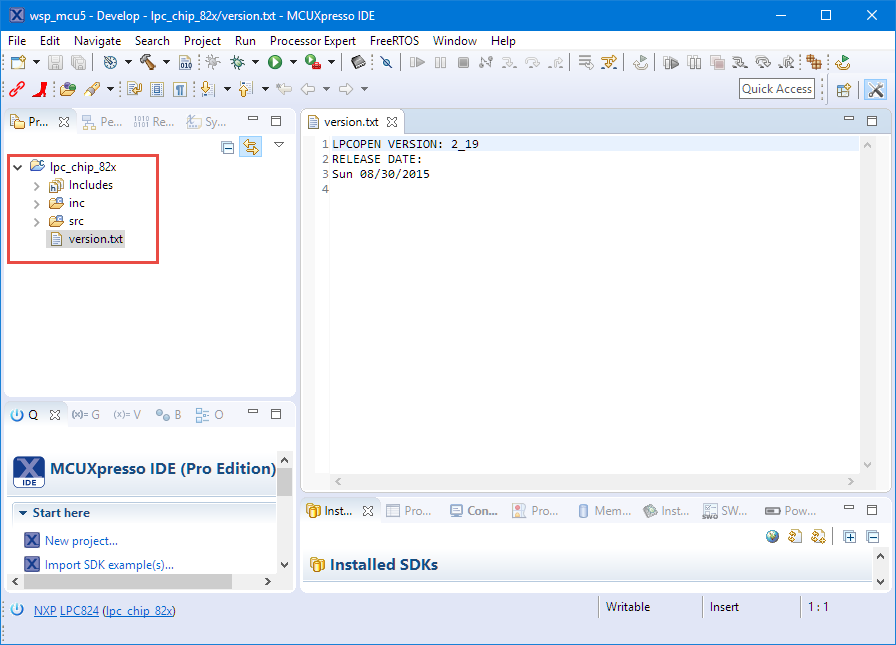
Chip Library in Workspace
Creating Project
The next step is to create a new project for the board. I use again the Quickstart panel with ‘New Project’:
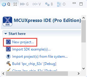
New Project
Select the LPC824:
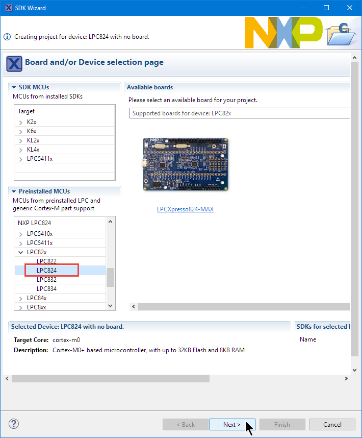
LPC824 in Wizard
Press next. Select LPCOpen C project:

LPCOpen C project
Press Next and give a project name:
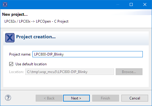
Project name
In the next dialog it should detect the chip library I have present in my workspace:
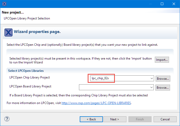
LPC Chip Libray for project
Press Next. In the next dialogs I use the defaults until I get to the point to finish the wizard and the project gets created in the workspace:
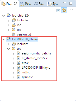
Blinky Project Created
Schematics and LEDs
Checking the schematics of the board, I can see tha the three LEDs on the board are connected to PIO0_17, PIO0_16 and PIO0_15:
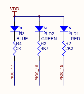
RGB LED on LPC800-DIP
The LEDs are connected with the cathode side to the microcontroller. So this means I have to put the ping LOW to turn then LED on (the LEDs are LOW-ACTIVE).
GPIO Pins
I add the following to the program:
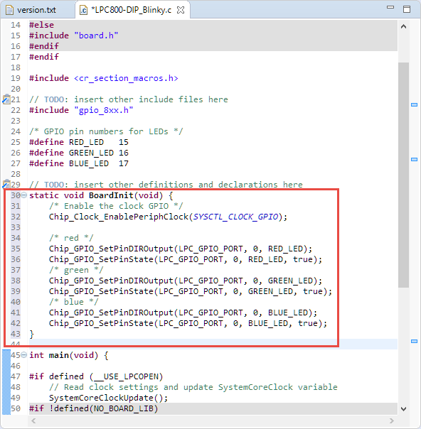
#include "gpio_8xx.h"

/* GPIO pin numbers for LEDs */
#define RED_LED   15
#define GREEN_LED 16
#define BLUE_LED  17
This includes the header file for the GPIO peripheral, and I have added defines for the GPIO pins used by the three LEDs.

GPIO declarations
GPIO Initialization
To use the GPIO pins, I have to initialize them. I do this in a ‘BoardInit()’ function which does the following:
- Enable the clocking for the GPIO peripheral
- Configure the pins as output pins
- Initialize them with a logic HIGH level. The LEDs are LOW active, so putting a HIGH (or TRUE) will turn it off.
The following is my BoardInit() function:
static void BoardInit(void) {
    /* Enable the clock GPIO */
    Chip_Clock_EnablePeriphClock(SYSCTL_CLOCK_GPIO);

    /* red */
    Chip_GPIO_SetPinDIROutput(LPC_GPIO_PORT, 0, RED_LED);
    Chip_GPIO_SetPinState(LPC_GPIO_PORT, 0, RED_LED, true);
    /* green */
    Chip_GPIO_SetPinDIROutput(LPC_GPIO_PORT, 0, GREEN_LED);
    Chip_GPIO_SetPinState(LPC_GPIO_PORT, 0, GREEN_LED, true);
    /* blue */
    Chip_GPIO_SetPinDIROutput(LPC_GPIO_PORT, 0, BLUE_LED);
    Chip_GPIO_SetPinState(LPC_GPIO_PORT, 0, BLUE_LED, true);
}
Added BoardInit
Delay
Because I need to delay the blinking of the LEDs, I add a very simple delay routine which burns CPU cycles:
static void delay(void) {
    /* very simply delay routine */
    volatile uint32_t cntr = 0x80000;
    while(cntr>0) { /* burn some cycles */
        cntr--;
        __asm volatile("nop\n");
    }
}

Added Delay
Board Initialization in main()
In main() I call the BoardInit() to initialize the hardware:
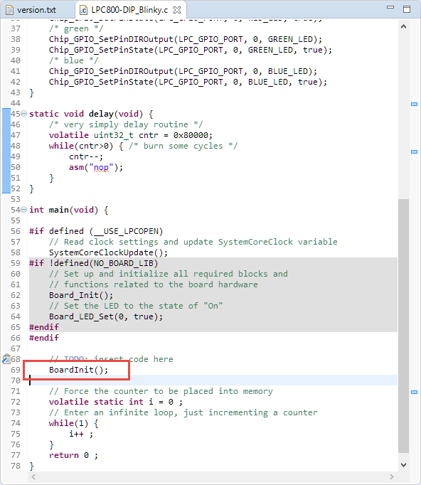
Added BoardInit in main
Blinky, Blinky, Blinky!
Finally, adding some code to do the blinky inside main(). With
Chip_GPIO_SetPinState(LPC_GPIO_PORT, 0, RED_LED, true);
the red LED is turned off, and with the following it is turned on:
Chip_GPIO_SetPinState(LPC_GPIO_PORT, 0, RED_LED, false);
Between the LED on/off I have added the calls to the delay routine to slow down things inside main():
    while(1) {
        Chip_GPIO_SetPinState(LPC_GPIO_PORT, 0, RED_LED, true);
        delay();
        Chip_GPIO_SetPinState(LPC_GPIO_PORT, 0, RED_LED, false);
        delay();
        Chip_GPIO_SetPinState(LPC_GPIO_PORT, 0, GREEN_LED, true);
        delay();
        Chip_GPIO_SetPinState(LPC_GPIO_PORT, 0, GREEN_LED, false);
        delay();
        Chip_GPIO_SetPinState(LPC_GPIO_PORT, 0, BLUE_LED, true);
        delay();
        Chip_GPIO_SetPinState(LPC_GPIO_PORT, 0, BLUE_LED, false);
        delay();
        i++ ;
    }
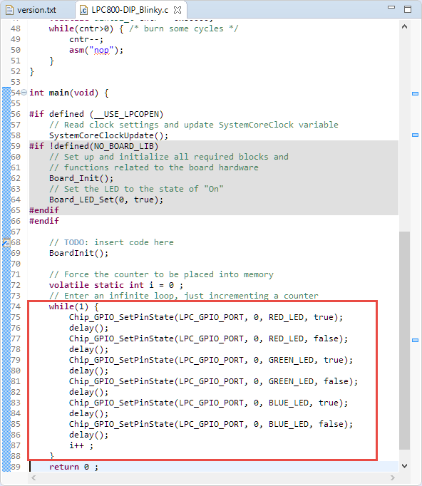
Added Blinky in main
Build
Use the ‘hammer’ in the Quickstart panel to build the project:
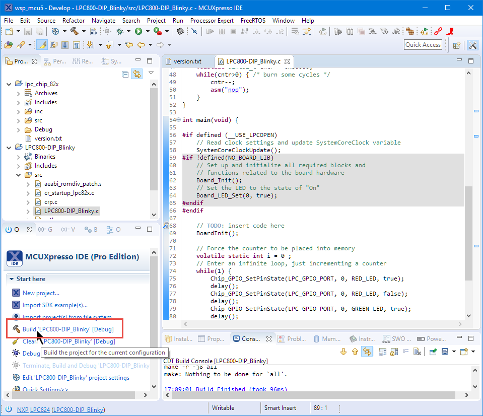
Build
This should build without any errors :-).
Debug
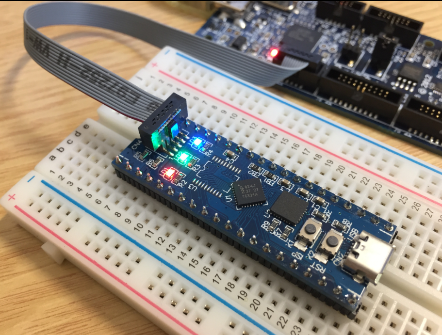
The board has SWD/JTAG header. I prefer this way and do not program the board with FlashMagic tool, because that way I can debug it. But this requires a SWD/JTAG probe like the LPC-Link2 which I use here.
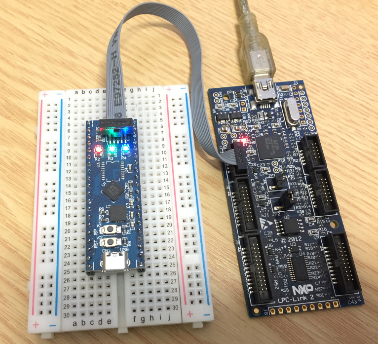
LPC-Link2 on the right
Connect the SWD cable to the SWD header on the LPC800-DIP board. In the bove case I have the jumper JP2 on the LPC-Link2 set, so I power the board from the LPC-Link2. If using another probe, you might need to power the LPC800 board with its micro USB cable.
Start the debugger with the ‘blue’ debug icon in the quickstart panel, and it should recognize the debug probe:
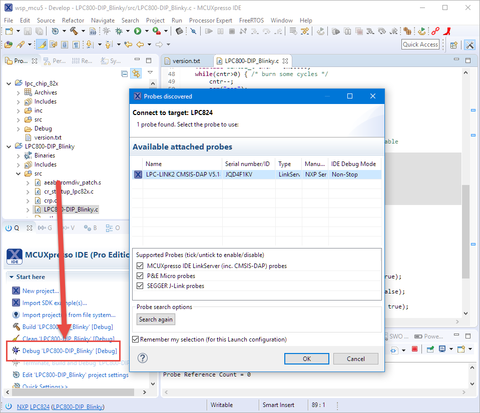
Debug
Press OK, and I’m debugging the board:
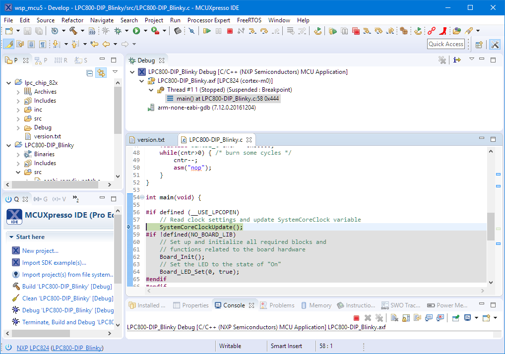
Debugging the Board
🙂
Summary
The LPC800-DIP board is a small and bread board friendly development platform with a Cortex-M0 on it which makes it ideal for smaller projects. For the LPC8xx series there is no MCUXpresso SDK (yet?). But MCUXpresso IDE comes with the LPCOpen SDK which makes the implementation of a blinky possible in a very short time. I appreciate that it has a SWD debug header so I can use it with my favorite JTAG/SWD debug probe and Eclipse.
I have been told by NXP that the LPC800-DIP board is not available for sale (yet?). NXP gave away many of these boards at the Embedded World 2017 show in Germany, so you might have been lucky and have a board on your desk you can use with this tutorial (or any other LPC800 board).
The project sources are on GitHub: https://github.com/ErichStyger/mcuoneclipse/tree/master/Examples/MCUXpresso/LPC800-DIP
💡 PS: I still have a few boards available at the Lucerne University of Applied Sciences and Arts which I can give away. First come, first serve 🙂
Happy DIPing 🙂
Links
- LPC800-DIP Schematics: https://community.nxp.com/community/lpc/blog/2017/03/20/lpc800-dip-schematic?et=watches.email.blog and https://community.nxp.com/community/lpc/blog/2017/03/20/lpc800-dip-schematic
- MCUXpresso IDE web page: http://www.nxp.com/mcuxpresso/ide
- MCUXpresso IDE community: http://www.nxp.com/mcuxpresso/ide/forum
- LPC-Link2 Debug Probe: http://www.nxp.com/products/microcontrollers-and-processors/arm-processors/lpc-cortex-m-mcus/lpc1100-cortex-m0-plus-m0/lpc-link2:OM13054
- Project on GitHub: https://github.com/ErichStyger/mcuoneclipse/tree/master/Examples/MCUXpresso/LPC800-DIP

Pingback: MCUXpresso IDE: S-Record, Intel Hex and Binary Files | MCU on Eclipse
Pingback: MCUXpresso IDE: Adding the Eclipse Marketplace Client | MCU on Eclipse
Pingback: MCUXpresso IDE: Importing Kinetis Design Studio Projects | MCU on Eclipse
Pingback: MCUXpresso IDE: Installing Processor Expert into Eclipse Neon | MCU on Eclipse
Pingback: MCUXpresso IDE: Terminate and Disconnect a Debug Session | MCU on Eclipse
asm(“nop”) will be optimized away depending on optimization settings; best not to do that or you’ll get different delays depending on options….
LikeLike
Hi Dave,
I 100% agree with what you say as a general statement. But I disagree in this case :-). If a compiler would touch my inline assembly code and remove it, then I would flag this as a serious bug, even for a NOP.
Second, the cntr variable is declared as volatile to ensure the compiler treats it as a ‘hot potatoe’ and does normal ‘load-and-store’ and does not keep it in the register. You are correct that the exact timing still will depend on the optimization level. But the compiler will never be able to remove it. I have checked that example with the gcc in MCUXpresso IDE and even with -O3 that NOP and counter loop is kept, as I expect it.
Thanks for raising that excellent point!
LikeLike
Probably the most correct way would be asm volatile: http://stackoverflow.com/questions/14449141/the-difference-between-asm-asm-volatile-and-clobbering-memory
But I don’t know what compiler you are using supports it.
LikeLike
I’m using one of the latest GNU for ARM Embedded. And yes, you are correct, the most correct way would be to use
__asm volatile ("nop\n");and GCC (at least the version I’m using: GNU Tools for ARM Embedded Processors 5 – Q3 2016) supports it.LikeLike
Also, regarding the delay, you may find interesting how arduino went to great lengths to get cycle precise delays.
https://github.com/arduino/Arduino/blob/b1231c39e9fa6d8602ac24305b07f074c1145633/hardware/arduino/avr/cores/arduino/wiring.c#L120
LikeLike
How similar is programming this board to programming the LPC1347 board?
LikeLike
If using the SWD/JTAG connector, programming is the same. The LPCXpresso board for LPC1347 (I assume the http://www.nxp.com/products/software-and-tools/software-development-tools/software-tools/lpcxpresso-boards/lpcxpresso-board-for-lpc1347:OM13045) has the advantage that it has a LPC-Link debug circuit on it.
LikeLike
I have three of those boards ordered. Thank you for the advice.
LikeLike
Pingback: First tinyK22 Board with NXP K22FN512 ARM Cortex-M4F | MCU on Eclipse
Pingback: New Concept for 2018 Mini Sumo Roboter | MCU on Eclipse
Hi Erich,
I’m doing the “same” example using the LPC1343 board.
I want to understand how may cycles (wasting nop) generate a 1ms delay.
Here my calculus:
F_clk = 72 MHz -> T_cycle (should this ~match the T_instruction?) = 1/72 MHz =~ 13.9 ns
n_Cycles = delay/T_cycle = 1 ms/13.9 ns =~ 72000
I created a constant for 1 ms:
#define DELAY_1ms ((uint32_t)72000)
and from here I derived other values:
#define DELAY_100ms ((uint32_t)100*DELAY_1ms)
#define DELAY_1s ((uint32_t)1000*DELAY_1ms)
The delay function has been defined as:
void delay_Nops(uint32_t nops)
{
volatile uint32_t counter;
for(counter = 0; counter <nops; counter++)
{
__asm volatile("nop\n");
}
}
It runs, but the delay doesn't correspond to the defined time. In fact it is more long…
Unfortunately In the MCUXpresso I didn't find the "watch time" function, so I can't figure out is the T_instruction assumption is it correct or not, and where is the error.
Could you please help me to find out what is wrong?
Many thanks!
Ale
LikeLike
You need to consider the overhead of your function call, plus because your counter is volatile it adds more overhead for each iteration.
I suggest you have a look at my implementation of waiting functions in https://github.com/ErichStyger/McuOnEclipseLibrary/blob/master/lib/src/McuWait.c
LikeLike
What a shame!
I remember with nostalgia your Wait PE-component, Erich! 😦
LikeLike
Yes, I know, I have been lacy ;-). But if you want to use the WAIT component, it is available for non-PE projects here: https://github.com/ErichStyger/McuOnEclipseLibrary/tree/master/lib/src
LikeLike
TNX Erich, also if dont include the enabled-watchdog…
LikeLike
Good day. As info, Coridium has a number of these devices for sale with their ARMbasic firmware pre-installed thereon. They are selling them for $10 USD each. I’ve a couple as I am getting back into embedded dev and they rang true on the cost/value scale. I believe that they have less than a hundred in stock at this time (Aug 2018). I understand that when they are gone, they may not be restocked. Anyways, you can get them here: https://www.coridium.us/coridium/shop/boards/bd07-special
Take care.
-t
LikeLike
Thank you for providing that link so I can pass it to students who want to get that board!
LikeLiked by 1 person
Pingback: Black Magic Open Source Debug Probe for ARM with Eclipse and GDB | MCU on Eclipse