After my first post using a Bluetooth module, things have evolved a bit. The challenge with these Bluetooth modules is: they look the same, but having different firmware. I did not fully realize that until I have ordered another bluetooth module from dx.com:
DX.com Bluetooth Module (HC-06)
That module comes already on a carrier, so I assumed I can use the same driver as for my other module. I was wrong :-(.
HC-05 or HC-06
My earlier module which I received from another source (without an adapter, see this post) has a different firmware on it, known as HC-05, while my DX.com module has a HC-06 firmware. To be clear: the modules are the same, but the software/firmware on it is different, and the firmware uses the pins differently too 😦

HC-06 and HC-05 (Source Wavesen Data Sheet)
💡 Check out this post which explains how to re-program the firmware of the device with firmware programming adapter: http://byron76.blogspot.ch/2011/09/hc05-firmware.html
The HC-05 has the ‘full’ firmware on it: many AT commands, and can be both master and slave module. The HC-06 firmware on the other hand only can be a slave device, with very limited AT commands.
Or in other words:
- The HC-05 module can build a connection to other modules. E.g. a Robot being a master and connecting to slave bluetooth module. Or in slave mode to make a wireless bridge to a notebook.
- The HC-06 module only can be a slave. This makes it only useful for say connecting a notebook as a master to a robot with a slave module e.g. for a wireless serial bridge.
For most use cases the HC-06 is enough, as typically I want to have a wireless UART connection to my devices from my notebook.
JY-MCU V1.5 Module
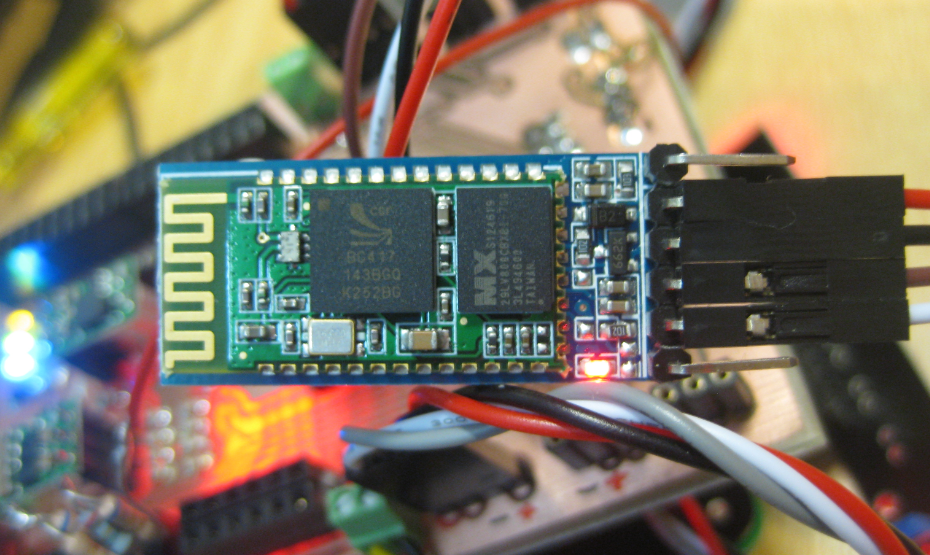
Below is an image of the JY-MCU HC-06 (JY-MCU V1.5) module. The module came with a 4-pin header, and I have added the pins for STATE and KEY, and removed the plastic around the module to get access to the pins:
HC-06 Top Side
Pins
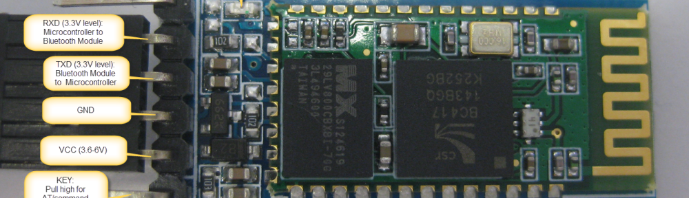
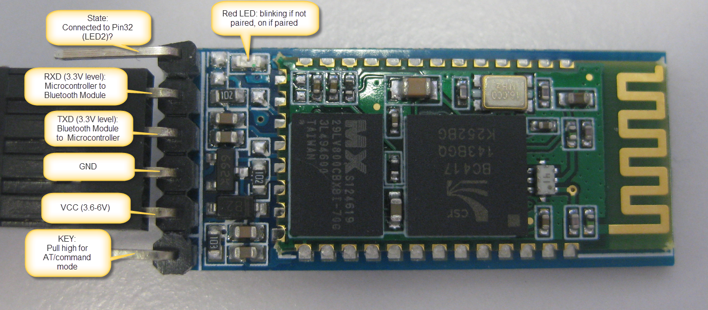
On the bottom side there are labels for the signal direction and voltage levels:

JY-MCU BT_BOARD V1.05 Bottom Side
- KEY: according to the data sheet, I need to pull-up this pin while power-on-reset of the module to enforce AT mode. I have not been able to verify this yet. I have been told that some modules have this pin not connected at all?
- VCC is indicated in the range of 3.6V-6V. The module worked for me both with 3.3V and 5V.
- GND: Ground
- TXD: serial output of the module, to be connected to RX of the microcontroller. Note that this signal is using 3.3V logic level
- RXD: serial input of the module, to be connected to the TX of the microcontroller. Note that this signal is using 3.3V logic levels.
- STATE: connected to LED2 (Pin32) of the module, but no meaning? At least on my module the pin was always low, regardless if paired or not.
Different AT commands
On the HC-05 module, I send “AT\r\n” to the device, and then it responds with “OK\r\n”.
But on the HC-06, the protocol is different 😦 I need to send “AT” (without the new-line characters), and I receive “OK” (without the new-line characters).
The logic analyzer shows this behavior too: AT command sent to the device:

AT Command sent to Device
OK response from the device with no “\r\n” at the end:

OK Response from the Device
The missing “\r\n” is present for all commands of the HC-06 firmware. As as this is not enough, there are very few command possible. The table below shows all the HC-06 firmware commands with the response:
| Command | Response | Comment |
|---|---|---|
| AT | OK | Used to verify communication |
| AT+VERSION | OKlinvorV1.8 | The firmware version (version might depend on firmware) |
| AT+NAMExyz | OKsetname | Sets the module name to “xyz” |
| AT+PIN1234 | OKsetPIN | Sets the module PIN to 1234 |
| AT+BAUD1 | OK1200 | Sets the baud rate to 1200 |
| AT+BAUD2 | OK2400 | Sets the baud rate to 2400 |
| AT+BAUD3 | OK4800 | Sets the baud rate to 4800 |
| AT+BAUD4 | OK9600 | Sets the baud rate to 9600 |
| AT+BAUD5 | OK19200 | Sets the baud rate to 19200 |
| AT+BAUD6 | OK38400 | Sets the baud rate to 38400 |
| AT+BAUD7 | OK57600 | Sets the baud rate to 57600 |
| AT+BAUD8 | OK115200 | Sets the baud rate to 115200 |
| AT+BAUD9 | OK230400 | Sets the baud rate to 230400 |
| AT+BAUDA | OK460800 | Sets the baud rate to 460800 |
| AT+BAUDB | OK921600 | Sets the baud rate to 921600 |
| AT+BAUDC | OK1382400 | Sets the baud rate to 1382400 |
That’s it.
Firmware Timing
As this is not enough, my driver did not work even with the new commands implemented. The HC-05 firmware as sending a response back in less than 300 ms, while the HC-06 firmware needs more than 500 ms until there is a response:

Delay between Command and Response
So for this I had to introduce a user configurable delay in the component.
Processor Expert Component
With this knowledge, the Processor Expert Bluetooth component has been updated to support both the HC-05 and HC-06 firmware:

Bluetooth Component Supporting HC-05 and HC-06
- Firmware to select between HC-05 and HC-06
- Configurable Response Time if the module needs longer for commands
- Optional State and CMD pins
If the HC-05 firmware is selected, then the component automatically disables the functionality methods not present/supported in the firmware (grayed out methods):

Bluetooth Module Methods
Command Line Interface
The Processor Expert component features an optional command line interface:
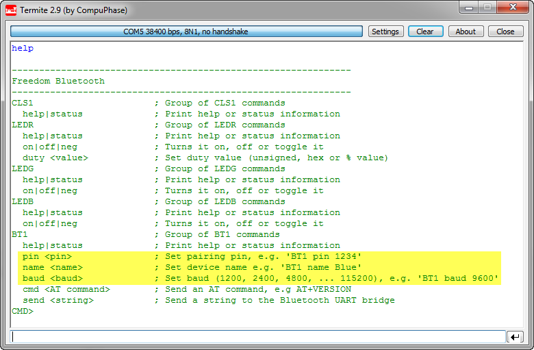
HC-06 Shell Commands
With this, I can change the pairing pin, device name or baud, beside of sending AT commands or sending a string over the wireless bridge.
💡 Changing the pairing/name/baud will be effective after resetting the device. Keep in mind if you change the baud, this will change the baud as well between the module and the microcontroller.
The ‘status’ command issues an AT command to the device to see if it responds, plus shows the firmware version:

BT1 Status with Module Firmware
❗ Status and AT commands can only be used if the device is not paired yet (means: while the red LED is blinking).
Connecting to the Bluetooth Module
The Bluetooth module runs the SPP (Serial Protocol over Bluetooth) protocol. So any device supporting SPP can connect to it. On a PC this looks like a virtual COM port. I show here the steps for Windows (running Windows 7).
❗ It seems that Apple (iPhone, iPAD, etc) does *not* support SPP, so connecting with an iPhone is not possible. Android (which I did not try) should work, or any PC machine with Bluetooth.
Before connecting, make sure the module is powered and ready to pair. The red LED on the module indicates the status:
- blinking: ready to pair
- steady on: paired
From the Device Manager, select ‘Add a Device’:

Device Manager with Add a Device
Then the new device should show up:
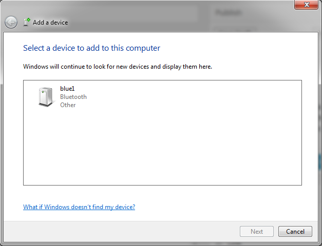
Add a device Dialog
💡 the name of the device shows here for me ‘blue1’, as I have named it as such. But it might show up for you as ‘linvor’ (default) or ‘other’.
Select the device and press ‘Next’. In the next dialog select ‘Enter the device’s pairing code’:

Enter the device’s paring code
The default pairing code is 1234:

Enter the pairing code for the device
Pressing next, and device drivers will be installed:

Installing device drivers
Then the device is ready to use:

Your Device is ready to use
And the confirmation dialog shows up:
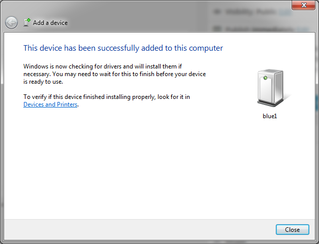
This device has been successfully added to this computer
COM Port used by Device
Checking the properties on the newly added device shows that it supports SPP. And it shows the virtual COM port used:

Device Services
❗ Note that if I check the COM ports in the device manager, then I see that actually two COM ports have been added. Only the one shown above with the SPP protocol will work. It is unclear to me why there is a second port?
Connecting to the Wireless Bluetooth Bridge
Using that COM port shown for the SPP service, I can connect with a terminal program on the host PC to my board. Basically this gives me a wireless bridge over Bluetooth to my board. So from my PC I can open a terminal window and type in some commands, which are parsed by the Shell on the FRDM board, and it responds back to the terminal on the PC:

Wireless Bluetooth Bridge Connection
❗ Make sure you use the COM port used for the SPP service, and that it matches the baud settings of the communication between the microcontroller and the Bluetooth module. I’m using above the default of 9600 baud. It is possible to change/increase the baud as explained above, as 9600 is not very fast. Only be sure that you not exceed the baud to a value which cannot be handled by your PC. It should work ok up to a baud of 115200.
Once connected, the red LED on the Bluetooth module is always on.

Pairing LED
While connected, the module is in ‘transparent’ mode, and does not accept AT commands. Below is an example where I try to send an AT command from the microcontroller while the Bluetooth module is connected to the host PC:
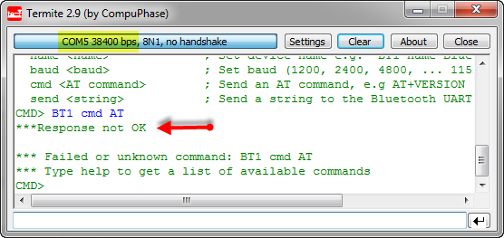
Trying to send AT commands from the microcontroller while connected to PC
Instead, what I send to the UART ends up transparently on the host PC:

Bluetooth Module in Transparent Mode
Wireless Bridge
Everything I send to the virtual COM port ends up on the Bluetooth module, which then sends the commands to the microcontroller using the RX and TX connection between the microcontroller and the module. With this, it is very easy to send/receive commands using the Processor Expert Shell component, and the implementation are just a few lines:
/** * \file * \brief This is the implementation module for the shell * \author Erich Styger * * This interface file is used for a console and terminal. * That way we can interact with the target and change settings using a shell implementation. */ #include "Shell.h" #include "CLS1.h" #include "LEDR.h" #include "LEDG.h" #include "LEDB.h" #include "BT1.h" static const CLS1_ParseCommandCallback CmdParserTable[] = { CLS1_ParseCommand, #if LEDR_PARSE_COMMAND_ENABLED LEDR_ParseCommand, #endif #if LEDG_PARSE_COMMAND_ENABLED LEDG_ParseCommand, #endif #if LEDB_PARSE_COMMAND_ENABLED LEDB_ParseCommand, #endif #if BT1_PARSE_COMMAND_ENABLED BT1_ParseCommand, #endif NULL /* sentinel */ }; /* Bluetooth stdio */ static CLS1_ConstStdIOType BT_stdio = { (CLS1_StdIO_In_FctType)BT1_StdIOReadChar, /* stdin */ (CLS1_StdIO_OutErr_FctType)BT1_StdIOSendChar, /* stdout */ (CLS1_StdIO_OutErr_FctType)BT1_StdIOSendChar, /* stderr */ BT1_StdIOKeyPressed /* if input is not empty */ }; void SHELL_Run(void) { unsigned char buf[32]; unsigned char bTbuf[32]; buf[0]='\0'; bTbuf[0]='\0'; CLS1_ParseWithCommandTable((unsigned char*)CLS1_CMD_HELP, CLS1_GetStdio(), CmdParserTable); for(;;) { (void)CLS1_ReadAndParseWithCommandTable(buf, sizeof(buf), CLS1_GetStdio(), CmdParserTable); (void)CLS1_ReadAndParseWithCommandTable(bTbuf, sizeof(bTbuf), &BT_stdio, CmdParserTable); } }Unbinding and Trouble Shooting
In case there are issues with connecting to the module, it is necessary to unbind and re-bind (connect) to the module. It happened to me sometimes I’m able to connect once, but then not any more. In that case the following steps help:
- Close any terminal program potentially connected to the Bluetooth virtual COM port.
- Unpower the Bluetooth module so it is not visible any more to the PC.
- Right click on the device in the Windows Device manager (or Devices and Printer group) and select ‘Remove Device’:
Unbinding Bluetooth Device
- Re-power the module: the red LED shall be blinking as not connected.
- Search for the device in the device manager (as above), and connect again to the device with a pairing pin.
- Connect to the module using the COM port specified for the SPP service.
That way I was always able to recover connection to my module. See as well this post which helped me to solve my problem.
Sources
All the component sources discussed are available on GitHub. Additionally, the FRDM-KL25Z Bluetooth example project has been updated to support both the HC-05 and HC-06 modules.
Happy Bluetoothing 🙂

