Need to debug your robot or drone? In a HSLU university research project I’m using a Pixhawk and PX4 based drone hardware. Pixhawk and PX4 is an open standard for drone hardware and firmware and runs with NuttX RTOS. It is mainly used for drones, but is very capable for any other kind of mobile robots.
With the Pixhawk 6x-RT there is a powerful flight controller, using the NXP i.MX RT1176 dual-core processor. While this and other controller hardware do offer a hardware debug probe, it is not a simple task as there are different pin-outs and connectors, making debugging a mess with different cables and adapters. To simplify this, I have now a unified debug CMSIS-DAP debug probe using the NXP LPC55S69 as processor, with all the different headers and UART adapters included: the MCU-Link-MR (Mobule Robots) debug probe.

Outline
This article describes the MCU-Link-MR debug probe. It is an open source hardware debug probe based on the NXP MCU-Link debug probe, but built as open source hardware with KiCAD and has different UART and debug headers added to work with different robot platforms, including Pixhawk ‘full’ and Pixhawk ‘mini’ ports.

The article describes the high-level design, and how to use the NXP LinkServer software and firmware to connect and debug the Pixhawk hardware.
Adapters
Prior this project, I had to buy and use multiple USB cables and adapter boards with an FTDI chip on it:

Such a setup is universal, but is rather messy with different cables, difficult to use in the field, plus the adapter board costs more than the debug probe. The MCU-Link already includes a UART-2-USB bridge, so all what is really needed are the extra connectors and and a reset button. This started the MCU-Link-MR project.
Design
The hardware has been designed with KiCAD V8.


The board has a size of 58×40 mm and the following features:
- Binary compatible with the original NXP MCU-Link CMSIS-DAP debug probe (LPC ISP mode, LPC55S69 MCU)
- Reset button for LPC55S69
- Reset button and signal to all target debug headers. Additionally signal is controlled by MCU-Link firmware.
- Standard ARM target debug header (10pin 2×1.27 mm) to debug any ARM Cortex target hardware
- Pixhawk Debug Full debug header (10pin JST-SH) with UART
- Pixhawk Debug Mini debug header (6pin JST-SH) with UART
- DCD-LZ Debug header (7pin JST-GHS) with UART
- Target UART for NavQPlus Companion Computer (6pin JST-GH)
- Hardware debugging the LPC55S69 through USB connector.

New debug firmware loading works the same as with the original MCU-Link debug probe with setting the LPC ISP jumper, as the hardware is compatible with it.
USB-C SWD Debug Connector
With the USB-C connector it is possible to use a debug probe for the LPC55S69 (same concept as in Open Source picoLink: Raspberry Pi RP2040 CMSIS-DAP Debug Probe):

UART Connection
The UART JST-GH connector is for the NavQPlus companion computer:

Note: The UART header for the NavQPlus includes RTS/CTS signals, but they are currently not supported by the MCU-Link firmware.
FMU Debug Console
The FMU is using 57600 baud for the debug console (PX4 System Console: https://docs.px4.io/main/en/debug/system_console.html):
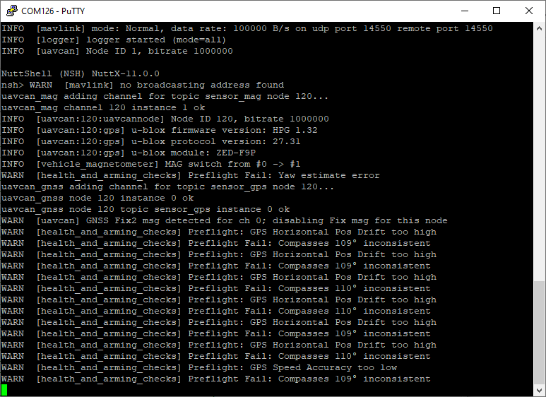
If using the ‘full’ Pixhawk base board, make sure to connect to the FMU debug port (NOT the I/O debug port):

Flashing with LinkServer
The easiest way to flash with the debug probe is using the LinkServer in command line mode (see as well LinkServer for Microcontrollers):
LinkServer flash MIMXRT1176xxxxx:MIMXRT1170-EVK-CM7-ONLY load px4_fmu-v6xrt_default.elf
which gives:
C:\NXP\LinkServer_1.5.30>LinkServer flash MIMXRT1176xxxxx:MIMXRT1170-EVK-CM7-ONLY load c:\tmp\px4_fmu-v6xrt_default.elf
INFO: Exact match for MIMXRT1176xxxxx:MIMXRT1170-EVK-CM7-ONLY found
INFO: Selected device MIMXRT1176xxxxx:MIMXRT1170-EVK-CM7-ONLY
INFO: Getting available probes
INFO: Selected probe #1 G5G1IHQ2OSE40 (MCU-LINK (r0FF) CMSIS-DAP V3.139)
INFO: MCU-Link firmware update CHECK: local firmware [3.140] can be programmed on the selected probe ([G5G1IHQ2OSE40] [MCU-LINK (r0FF) CMSIS-DAP V3.139])
Firmware update CHECK: - the update can be performed using `AUTO` mode
Ns: MCUXpresso IDE RedlinkMulti Driver v11.9 (Apr  5 2024 19:43:49 - crt_emu_cm_redlink.exe build 47)
Pc: (  0) Reading remote configuration
Wc(03). No cache support.
Nc: Found chip XML file in C:\Users\erich\AppData\Local\Temp\tmphbumz742\MIMXRT1176xxxxx.xml
Pc: (  5) Remote configuration complete
Nc: Reconnected to existing LinkServer process.
Wc: ============= SCRIPT: RT1170_connect_M7.scp =============
Wc: RT1170 Connect M7 Script
Wc: DpID = 6BA02477
Wc: APID = 0x84770001
Wc: View cores on the DAP AP
Wc: TAP 0: 6BA02477 Core 0: M7  APID: 84770001 ROM Table: E00FD003*
Wc: ============= END SCRIPT ================================
Nc: Probe Firmware: MCU-LINK (r0FF) CMSIS-DAP V3.139 (NXP Semiconductors)
Nc: Serial Number:  G5G1IHQ2OSE40
Nc: VID:PID:  1FC9:0143
Nc: USB Path: 0003:0013:00
Nc: Using memory from core 0 after searching for a good core
Pc: ( 30) Emulator Connected
Pc: ( 40) Debug Halt
Pc: ( 50) CPU ID
Nc: debug interface type      = CoreSight DP (DAP DP ID 6BA02477) over SWD TAP 0
Nc: processor type            = Cortex-M7 (CPU ID 00000C27) on DAP AP 0
Nc: number of h/w breakpoints = 8
Nc: number of flash patches   = 0
Nc: number of h/w watchpoints = 4
Nc: Probe(0): Connected&Reset. DpID: 6BA02477. CpuID: 00000C27. Info: <None>
Nc: Debug protocol: SWD. RTCK: Disabled. Vector catch: Disabled.
Ns: Content of CoreSight Debug ROM(s):
Nc: RBASE E00FD000: CID B105100D PID 000008E88C ROM (type 0x1)
Nc: ROM 1 E00FE000: CID B105100D PID 04000BB4C8 ROM (type 0x1)
Nc: ROM 2 E00FF000: CID B105100D PID 04000BB4C7 ROM (type 0x1)
Nc: ROM 3 E000E000: CID B105E00D PID 04000BB00C Gen SCS (type 0x0)
Nc: ROM 3 E0001000: CID B105E00D PID 04000BB002 Gen DWT (type 0x0)
Nc: ROM 3 E0002000: CID B105E00D PID 04000BB00E Gen (type 0x0)
Nc: ROM 3 E0000000: CID B105E00D PID 04000BB001 Gen ITM (type 0x0)
Nc: ROM 2 E0041000: CID B105900D PID 04001BB975 CSt ARM ETMv4.0 type 0x13 Trace Source - Core
Nc: ROM 2 E0042000: CID B105900D PID 04004BB906 CSt type 0x14 Debug Control - Trigger, e.g. ECT
Nc: ROM 1 E0043000: CID B105900D PID 04001BB908 CSt CSTF type 0x12 Trace Link - Trace funnel/router
Nc: NXP: MIMXRT1176xxxxx
Nc: DAP stride is 1024 bytes (256 words)
Nc: Inspected v.2 External Flash Device on SPI using SFDP JEDEC ID MIMXRT1170_SFDP_QSPI.cfx
Nc: Image 'iMXRT1170_SFDP_FlexSPI1_A_QSPI Apr  5 2024 18:35:58'
Nc: Opening flash driver MIMXRT1170_SFDP_QSPI.cfx
Nc: Sending VECTRESET to run flash driver
Nc: Flash variant 'iMXRT1170_SFDP_FlexSPI1_A_QSPI Apr  5 2024 18:35:58' detected (64MB = 1024*64K at 0x30000000)
Nc: Closing flash driver MIMXRT1170_SFDP_QSPI.cfx
Pc: ( 65) Chip Setup Complete
Pc: ( 70) License Check Complete
Nt: Loading 'px4_fmu-v6xrt_default.elf' ELF 0x30020000 len 0x2023C8
Nc: Opening flash driver MIMXRT1170_SFDP_QSPI.cfx (already resident)
Nc: Sending VECTRESET to run flash driver
Nc: Flash variant 'iMXRT1170_SFDP_FlexSPI1_A_QSPI Apr  5 2024 18:35:58' detected (64MB = 1024*64K at 0x30000000)
Pb: 1 of 3 (  0) Writing sectors 2-17 at 0x30020000 with 1048576 bytes
Ps: (  0) at 30020000: 0 bytes - 0/1048576
Ps: (100) at 30020000: 1048576 bytes - 1048576/1048576
Nc: Sectors written: 0, unchanged: 16, total: 16
Pb: 2 of 3 ( 49) Writing sectors 18-33 at 0x30120000 with 1048576 bytes
Ps: (  0) at 30120000: 0 bytes - 0/1048576
Ps: (100) at 30120000: 1048576 bytes - 1048576/1048576
Nc: Sectors written: 0, unchanged: 16, total: 16
Pb: 3 of 3 ( 99) Writing sectors 34-34 at 0x30220000 with 9160 bytes
Ps: (  0) at 30220000: 0 bytes - 0/9160
Ps: (100) at 30220000: 65536 bytes - 65536/9160
Nc: Sectors written: 0, unchanged: 1, total: 1
Nc: Closing flash driver MIMXRT1170_SFDP_QSPI.cfx
Pb: (100) Finished writing Flash successfully.
Nt: Loaded 0x2023C8 bytes in 343ms (about 6140kB/s)
Nt: Reset target (system)
Wc: ============= SCRIPT: RT1170_reset_M7.scp =============
Wc: SYSTEM Reset
Wc: DpID = 6BA02477
Wc: TAP 0: 6BA02477 Core 0: M7  APID: 84770001 ROM Table: E00FD003*
Wc: TAP 0: 6BA02477 AP   1:     APID: 24770011 ROM Table: E00FF003
Wc: TAP 0: 6BA02477 AP   2:     APID: 54770002 ROM Table: 00000002
Wc: APID = 0x84770001
Wc: View cores on the DAP AP
Wc: TAP 0: 6BA02477 Core 0: M7  APID: 84770001 ROM Table: E00FD003*
Wc: R15 = 0x00223104
Wc: Vector table SP/PC is the reset context.
Wc: PC = 0x300023A9
Wc: SP = 0x202447BC
Wc: XPSR = 0x01000000
Wc: VTOR = 0x30002000
Wc: Set DEMCR = 0x010007F1
Wc: ============= END SCRIPT ==============================
Flashing with GDB
Loading new firmware with gdb:
LinkServer gdbserver MIMXRT1176xxxxx:MIMXRT1170-EVK-CM7-ONLY
which gives:
C:\NXP\LinkServer_1.5.30>LinkServer gdbserver MIMXRT1176xxxxx:MIMXRT1170-EVK-CM7-ONLY
INFO: Exact match for MIMXRT1176xxxxx:MIMXRT1170-EVK-CM7-ONLY found
INFO: Selected device MIMXRT1176xxxxx:MIMXRT1170-EVK-CM7-ONLY
INFO: Getting available probes
INFO: Selected probe #1 G5G1IHQ2OSE40 (MCU-LINK (r0FF) CMSIS-DAP V3.139)
INFO: MCU-Link firmware update CHECK: local firmware [3.140] can be programmed on the selected probe ([G5G1IHQ2OSE40] [MCU-LINK (r0FF) CMSIS-DAP V3.139])
Firmware update CHECK: - the update can be performed using `AUTO` mode
GDB server listening on port 3333 in debug mode (core cm7)
Semihosting server listening on port 4444 (core cm7)
In another console:
arm-none-eabi-gdb build/px4_fmu-v6xrt_default/px4_fmu-v6xrt_default.elf -ex "target extended-remote :3333"
Which gives:
C:\NXP\MCUXpressoIDE_11.9.1_2170\ide\tools\bin>arm-none-eabi-gdb
GNU gdb (Arm GNU Toolchain 12.3.Rel1 (Build arm-12.35)) 13.2.90.20230627-git
Copyright (C) 2023 Free Software Foundation, Inc.
License GPLv3+: GNU GPL version 3 or later <http://gnu.org/licenses/gpl.html>
This is free software: you are free to change and redistribute it.
There is NO WARRANTY, to the extent permitted by law.
Type "show copying" and "show warranty" for details.
This GDB was configured as "--host=i686-w64-mingw32 --target=arm-none-eabi".
Type "show configuration" for configuration details.
For bug reporting instructions, please see:
<https://bugs.linaro.org/>.
Find the GDB manual and other documentation resources online at:
    <http://www.gnu.org/software/gdb/documentation/>.

For help, type "help".
Type "apropos word" to search for commands related to "word".
(gdb)
Connect:
(gdb) target remote localhost:3333
Which gives:
(gdb) target remote localhost:3333
Remote debugging using localhost:3333
warning: No executable has been specified and target does not support
determining executable automatically.  Try using the "file" command.
0x300023a8 in ?? ()
Load the file:
(gdb) file c:/tmp/px4_fmu-v6xrt_default.elf
which gives:
(gdb) file c:/tmp/px4_fmu-v6xrt_default.elf
A program is being debugged already.
Are you sure you want to change the file? (y or n) y
Then load the file:
(gdb) load
which gives:
(gdb) load
Loading section .boot_hdr, size 0x2000 lma 0x30020000
Loading section .vectors, size 0xe70 lma 0x30022000
Loading section .itcmfunc, size 0x3b648 lma 0x30022e70
Loading section .text, size 0x1c2b48 lma 0x3005e4b8
Loading section .init_section, size 0x158 lma 0x30221000
Loading section .ARM.exidx, size 0x8 lma 0x30221158
Loading section .data, size 0x10a0 lma 0x30221160
Loading section .ramfunc, size 0x1c8 lma 0x30222200
Start address 0x300223a8, load size 2106312
Transfer rate: 3002 KB/sec, 15374 bytes/write.
Exit gdb:
(gdb) exit
Enclosure
To protect the board, I have added as laser-cut PMMA cover: simple and cheap:
I might design a 3D printed enclosure too, but so far the one above is working fine. You can find the file(s) in the ‘enclosure’ sub-folder on GitHub.
Summary
The v0.1 hardware has been assembled and tested. Debugging works fine, plus the UART connection on the UART header. But the UART on the other debug header connections are not functional because I’ve made a mistake with the protection diodes for it. That’s why there is a v0.2 design underway which has this fixed. I should get that version middle of next week/mid of May operational. So if you want to try it out yourself, go with the v0.2 design on GitHub, or simply connect the UART signals to the UART header (this is what I did as a workaround).
Even with the v0.1 design I’m very happy: less cables, less adapters, easier debugging of my drone platform and hardware.
Happy Hawking 🙂
Links
- GitHub: https://github.com/ErichStyger/MCU-Link-MR
- NXP MCU-Link debug probe: https://www.nxp.com/design/design-center/software/development-software/mcuxpresso-software-and-tools-/mcu-link-debug-probe:MCU-LINK
- KiCAD: https://www.kicad.org/
- Holybro Pixhawk debug adapter: https://holybro.com/products/pixhawk-debug-adapter
- Previous version of MCU-Link debug probe with KiCAD: Versatile OSHW Mini MCU-Link Debug Probe: External, On-Board, or Embedded
- PX4 website: NXP MCU-Link Debug Probe with PX4

Nice article Erich! Kudos!!!
If you likes Robots too, these tutorials could help you: https://www.youtube.com/@robots5
They will create more videos explaining how to use Micro-ROS, pySimCoder and Gazebo for robots development.
LikeLike