One success factor of the Arduino platform is the broad availability so-called ‘shields’: hardware plugin-modules which extend the capability of platform. Shieldlist.org currently lists 288 different shields available! Clearly, Freescale wants to benefit from that ecosystem with the Freedom FRDM-KL25Z board which features Arduino compatible headers. Time to use the Freedom board with an Arduino shield :-).

Data Logger Shield on Top of Freedom Board
Data Logger Shield Hardware
I ordered a the Adafruit Data Logger Shield as a kit: to solder such a kit is fun :-), and gives me the freedom what to put on the board. The schematics of the shield can be found here.
The board features an SD card with level shifter (required to work with 3.3V and 5V devices), two LED’s, a reset button, an I2C battery buffered realtime clock plus a prototype area. The minimal SD card pins (MISO, MOSI, DeviceSelect, BusCock) and I2C (SDA, SCL) bus are connected to the shield connector rows, while the two LEDs and the card write protect and card detect pins can be routed to any pins with a wire or any other kind of connection.

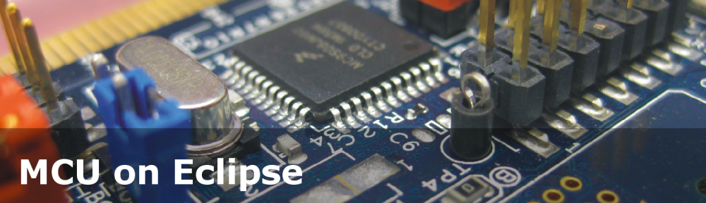
Data Logger Top View
In above picture the green wire is for WP (SD card Write Protection pin), the white wire is for the CD (SD Card Detect) pin. The yellow wires are for the red and green LED.
Freedom_FatFS Application
The application is Eclipse based CodeWarrior for MCU10.3 application. It uses the SD card with the open source FatFS file system.
❗ The FAT_FileSystem and SD_Card component have been updated to work with Kinetis. So make sure you use the latest component from EmbeddedComponents for this project.

Freedom_FatFS Processor Expert Components
- GenericTimeDate: needed for date and time information, as the file system needs date/time attributes for files on the file system
- Wait: generic busy wait routines, needed by the SD card driver because initialization of the SD card driver needs to wait for a time as specified in the SD card standard.
- Timeout: As SD card operations can take a very long time (several hundreds of milliseconds), this timeout driver allows to wait for a given time.
- SPIMaster_LDD: implements the SPI bus driver using interrupts.
- FAT_FileSystem: Implements the FAT file system.
- SD_Card: Low level SD card driver implementing the memory device.
- TimerInt_LDD and TimerUnit_LDD: implement a 10 ms timer used for the Timeout component.
- Init_GPIO: Init components used for pull up resistors for the WP and CD signals (see this tutorial).
- LED and GPIO_LDD: Driver for the RGB LED on the Freedom board (see this tutorial). Note that the signal for the blue RGB LED is used for the SD card SPI clock signal by the Data Logger Shield.
- BitIO_LDD: Used for the green and red LED on the shield (see this tutorial).
The project and components can be easily changed for any other SD cards. In any case, here are tips and hints how the project is configured:
KL25Z with 48 MHz
In order to run the SPI bus with up to 12 MHz, the CPU core clock is configured to run at 48 MHz:

48 MHz Core Clock
SPIMaster_LDD Configuration
The SPI component needs to be configured for the MISO, MOSI and CLK pins, *without* ❗ Chip select and two ❗ clock configurations, each with ‘MSB first’, ‘Low Clock polarity’ and ‘capture on leading edge’:

SPI Configuration
The Attribute Set 0 needs to point to Clock rate index 0, and the so the Attribute Set 1 to Clock rate index 1. The reason is that we need to SPI clock speeds: a maximum of 400 kHz for card initialization and up to 20 MHz for normal operation. What we can achieve here is 375 kHz and 12 MHz.
The two speed modes need to be set in the clock rate settings:

Clock Rate Settings
In the Timing Dialog the two SPI clock speeds need to be configured with ‘list of values’:

Timing Dialog
The two speed modes are referenced from the SD_Card component properties:

Slow and Fast Speed Modes
Timeout Component
As the SD card requires up to several hundreds of milliseconds delay, the Timeout component is used.

SD_Card Timeout Properties
For this a 10 ms timer is configured with the TimerInt_LDD component. What easily gets missed is to call the AddTick() method in Events.c from the 10 ms timer interrupt:
/*
** ===================================================================
**     Event       :  TI1_OnInterrupt (module Events)
**
**     Component   :  TI1 [TimerInt_LDD]
**     Description :
**         Called if periodic event occur. Component and OnInterrupt
**         event must be enabled. See  and
**         methods. This event is available only if a <Interrupt
**         service/event> is enabled.
**     Parameters  :
**         NAME            - DESCRIPTION
**       * UserDataPtr     - Pointer to the user or
**                           RTOS specific data. The pointer passed as
**                           the parameter of Init method.
**     Returns     : Nothing
** ===================================================================
*/
void TI1_OnInterrupt(LDD_TUserData *UserDataPtr)
{
  TMOUT1_AddTick();
}
WP and CD Pins
Optionally the SD card holder can provide WP (Write Protect) and CD (Card Detect) signals. They are available in the SD_Card component settings:

CD and WP Pins
If the signals do not have pull-ups or pull-down resistors on the board (as for my shield), they need to be configured in ‘pin-sharing’ mode and with pull-ups enabled (see this tutorial).
The WP signal is connected to the shield D8 line, and the CD signal is connected to D9.
LED’s
The projects used the RGB LED on the Freedom board plus the two LED’s on the Shield. The two shield LED’s are connected to the shield D7 and D6 lines.

LED Components in Component View
Example Code
The example code is in ProcessorExpert.c:
static FATFS fs;
static FIL fp;

static void Test(void) {
  UINT bw; /* number of bytes written */

  if (FAT1_isDiskPresent()) { /* if no hardware CardDetect pin is assigned, it will always return TRUE */
    LED_Rd_On(); /* turn red RGB LED on */
    FAT1_mount(0, &fs); /* mount file system */
    if (!FAT1_isWriteProtected()) { /* if no hardware WritePtotect pin is assigned, it will always return FALSE */
      LED_Gr_On(); /* turn green RGB LED on */
      if (FAT1_open(&fp, "./test.txt", FA_CREATE_ALWAYS|FA_WRITE)!=FR_OK) { /* open file, will always create it if not already on disk */
        for(;;){} /* error! */
      }
      if (FAT1_write(&fp, "Hello World!", sizeof("Hello World!")-1, &bw)!=FR_OK) { /* write string to file */
        for(;;){} /* error! */
      }
    }
    (void)FAT1_close(&fp); /* close file */
    FAT1_mount(0, NULL); /* unmount file system */
  }
}
If a card is inserted, the Red RGB LED will be on and the file system will be mounted. If the card has not the write protection tab on, it will write a file ‘test.txt’ with an example text in it.
Summary
For now I only have this shield, and it worked very well with the Freedom board. The shield has an I2C Real-Time-Clock on it for which I did not wrote a driver yet. That would give me a battery backed up clock which would make it ideal for a data logger application. Again, still some work to do :-).
I need to check/measure the SD card speed, but for now it is reasonable for my tests. For sure I will need to extend my Shell Project with the SD card capabilities.
The project and sources is available from this link. Code size with gcc and even not optimized at all is less than 18 KByte, so very reasonable.
Happy Shielding 🙂

Pingback: Arduino Data-Logger Shield with the FRDM-KL25Z Board « adafruit industries blog
Pingback: Hands-on Review: $12.95 Freescale Freedom Platform for Freescale Kinetis L microcontroller based on ARM Cortex-M0+ processor | Steve Leibson
Pingback: A Generic I2C High Level Driver | MCU on Eclipse
Pingback: Processor Expert Maxim I2C RTC Driver the Arduino Data Logger Shield | MCU on Eclipse
Pingback: CSI Crime Scene Investigation with I2CSpy and Freedom Board | MCU on Eclipse
Hi there,
First of all Thanks for this HOWTO. Trying to do it for myself I got stuck waiting for SD1_DataReceivedFlag. The problem is that this flag is set in your SD1.c file at the bottom
void SM1_OnBlockReceived(LDD_TUserData *UserDataPtr)
{
SD1_DataReceivedFlag=TRUE;
/* Calling inherited event */
}
While SM1 is the SPI Object. This Function is in my Events.c and by including it via
extern bool SD1_DataReceivedFlag;
it now works. Maybe i overread it but i couldnt find it in the text. This info could be useful for others too.
Bis dann,
Julian
P.S. you got some nice photographic skillz 😉
LikeLike
Hi Julian,
I did not point out all the details. For this I have posted the full project. You are right, that code in Events.c easily get missed (happend to me several times too), so thanks for pointing to this.
Erich
LikeLike
Hi Erich,
I had the same problem. This project when compiled has an empty onBlockReceived event.
void SM1_OnBlockReceived(LDD_TUserData *UserDataPtr)
{
/* Write your code here … */
}
Which causes the program to hang waiting for the data received flag.
while(!SD1_DataReceivedFlag){}
Thanks for all the great PE components. You do a great service to Freescale and the embedded community.
Jeff
LikeLike
Hi Jeff,
good if things are solved on your end, otherwise let me know.
Yes, the ‘events’ model in Processor Expert is powerful, but a constant source of missing implementing the hook itself, especially if porting one project to another. I’m considering to add to my own created components a dual interface for components with events: a normal ‘Events.c’ kind of interface, plus an interface which allows the calling application to install the hook with a function pointer: uses little more RAM, but avoids mistakes.
LikeLike
Hi Erich,
I’ve implemented this project for a K70, and my write throughput is extremely low.
With the SPI clock at 12.5MHz, I’m only seeing ~100KB/s.
Having a K70, I’m sure you’re wondering why I would use SPI and not use the SDHC…
Two reasons:
1 – we’re considering having multiple uSD cards connected via SPI, so writing via SPI is not a wasted lesson.
2 – I’ve used the SDHC, and still get low throughput! (depending on the card I get ~250-300 KB/s)
I keep the SDHC clock at ~5MHz, as going faster results in my program erroring out in the FATFs writes.
My throughput calculations are calculated by timing the writing of an 8MB file to the card. The data is simply a 512 byte buffer that is written repetitively.
What kind of throughput do you get when using SPI mode ?
If you have done similar with SDHC, what kind of throughput did you achieve there ?
Any “gotchas” that I may be overlooking that I can look at ?
Thanks,
Chandler
LikeLike
Hi Chandler,
Yes, I have been as well disappointed by the read/write performance. My conclusion is that it heavily depends on the buffer size, plus on the SD card used. I have seen SD card differences by several factors. It seems to me that especially larger and newer SD cards are slower. I have found a few 512 MByte (yes, that small!) which have the best read/write performance. Simply because their internal flash block size is smaller.
On https://github.com/ErichStyger/mcuoneclipse/tree/master/Examples I have a simple benchmark example for the K60 (SDHC) and K70 (SPI).
My results are (all for a file with 100’000 bytes):
K60/SDHC (results first with a micrSD card, and a normal SD card):
– creating file: ~4000 ms / 4600 ms
– reading file: ~2500 ms / 2500 ms
– copy file: ~6400 ms / 9200 ms
here you already see that there can be big differences.
As for SDHC, I had filed a ticket because using multiple pins had no improvements on my side. I still need to follow the advice, but basically it is about increasing buffer size (I did not verify this).
I’ll check the numbers on the KL25Z and with a ColdFire V2 and post it up here.
As a side note: I have improved some of the SPI driver part in the sources on GitHub: basically using more block transfers than writing/reading single bytes. This had a positive performance impact. Not sure if you are using the drives from GitHub, but this might give you a performance boost.
Best regards,
Erich
LikeLike
Hi Chandler,
I have published another example with ColdFire V2 52259 (using SPI), available on https://github.com/ErichStyger/mcuoneclipse/tree/master/Examples/TWR-52259/MCF52259_FatFS
And I get:
CMD> run benchmark
Benchmark: open file, write 10k times 10 bytes (100’000 bytes), close file:
Deleting any existing files…
Creating benchmark file…
1490 mseconds needed for command.
Reading benchmark file…
960 mseconds needed for command.
Benchmark: copy file (100’000 bytes):
Going to copy file…
2850 mseconds needed for command.
done!
LikeLike
Thanks Erich!
I have used the examples and drivers on GitHub before.
I’ll take a look at the updated examples/drivers soon.
I’m currently working on stripping down the SDHC PE code to remove the software overhead.
Once I have that working, I will implement multiple block transfers.
I’ll then test writing raw sequential blocks to the card to see what kind of speeds I can get, as this should be the fastest method possible.
(Using CrystalDiskMark on the PC to test cards, I’ve seen sequential write speeds as high as 18MB/s…I don’t expect to get anywhere near there, but I would like to break the MB/s rate on the K70!)
LikeLike
Hi Erich,
I was finally able to get some work done with the SDHC and I am very happy with the results.
I stripped down the PE driver and made it more straight forward and efficient.
One example was the write, where the PE driver would first do a read before a write. While this makes sense to handle writing sizes smaller than a block, a simple “if write size == block size” could have saved the unnecessary read overhead!
Since the PE code was already setup using single block transfers, I first tested some writes while varying the SDHC clock speed.
For 1MB of data and a 50MHz SD clock, the write time was ~8 seconds.
I then took measurements while slowing the clock down in increments all the way to 1.25MHz, where to my surprise, the 1MB of data only took ~10 seconds.
I scoped all of the signals and noticed a ~4ms pause between every block, which was apparently not dependent on the SD clock.
A single 512-byte block with a 50MHz clock was writing in ~25 microseconds…so of the 8 seconds to write 1MB, only about 50ms was data the strobing while the rest of the time was a busy state (presumably as the card actually wrote the data).
Next I implemented multi block transfers and tested with a 50MHz SD clock.
I first tested 16 blocks per transfer and was seeing a 1MB transfer time of ~550ms!
Unfortunately, here is where I got some strange behavior…
At 50MHz clock, I would sometimes get in an error state I could not recover from.
At 37.5MHz clock, it worked 100% of the time, AS LONG AS I was debugging, but I often hit the error state when not debugging.
After testing multiple clock speeds, it appeared that 18.75MHz seemed to work 100% of the time, even when not debugging.
To get a more realistic data transfer measurement, I measured transfers of 128MB.
At 18.75MHz SD clock with 16 block transfers, the write time was 80 seconds, giving a write speed of 1.6MB/s.
The last test was to increase the number of blocks per write. I tested 32, 64, and 128.
With 128 block transfers, the full 128MB of data took only 21 seconds for a transfer speed of ~6MB/s !
I’m unable to increase the blocks per write further without running out of on-chip memory. (I still need to get external DDR functioning correctly…)
However, unless I can figure out why the higher clock speeds result in errors, I’m essentially at the data write limit anyway.
I am very pleased with the write time of 21 seconds for 128MB of sequential data.
Although this is purely write time, the rate is MUCH higher than what I saw trying to use PE (more than 50x faster!).
LikeLike
Hi Chandler,
that’s really good news. I wonder how I could apply this to the SPI based driver too. Are you saying you did the changes on the low level PEx code? Or at the interface layer of FatFs? Would you be so kind to share your details so I could incorporate this to the files on the MCUonEclipse GitHub page so everyone could benefit?
Many thanks,
Erich
LikeLike
Hi Erich,
This is all low level SDHC code with no FatFS involvement. Although our project will use a FAT32 file system, the key for us is storing large chunks of sequential data quickly. With the emphasis on “quickly” and the files being sequential, I wouldn’t want the overhead of FatFS. Our project will handle the FAT table with some simple streamlined code as we know how data will be laid out, etc.
As a side note, I was able to test increased number of blocks per write, testing 256, 512, 1k, 2k, and 4k blocks per command. At 512 and above, the 128MB write time was ~16.5s. Considering the time to strobe 128MB at my SD clock speed is a little over 14 seconds, ~2.5 additional seconds for other commands and busy delays sounds about right. The only way I could get faster would be being able to increase the SD clock speed without errors.
The code I have now has no error checking and is just basic code in the main function. I used the source code from the PE driver as a guide. I am still using the SDHC_Init component to initially setup the SDHC.
*** HOWEVER, note that this basic init function is INCOMPLETE! Part of the initialization process should involve setting internal pullups on the the data lines. (This was a gotcha that took me some time to find unexplained errors. The weird thing is that the init function in the SDHC LDD component does the pin setup correctly…)
The basic flow of the program is as follows:
// note that all sent commands below poll command complete flag in the IRQSTAT register before continuing to next step
// additionally, transfer commands will poll transfer complete flag after the command complete flag is set
// some of the bit masks for arguments and checks I have as DEFINES, but I don’t have the header in front of me right now…you should be able to find them in the SDHC_LDD generated code
– detect card is inserted via card detect pin
// reset all cards
set CMDARG to 0
send CMD0 (no response type)
// test high voltage and check pattern
set CMDARG to 0x1AA
send CMD8 (response type 48)
test CMDRSP0 for 0x1AA; proceed further if response matches
// wait for power up
set powered flag to false
while !powered {
set CMDARG to 0
send CMD55 (response type 48)
set CMDARG to CCS | VOLTAGE_RANGE
send ACMD41 (response type 48)
test CMDRSP0 for CARD_POWER_STATUS;
if bit is high, set powered to true to break from loop
}
// begin card registration
set CMDARG to 0
send CMD2 (response type 136)
// RCA request
set CMDARG to 0
send CMD3 (response type 48)
store RCA from CMDRSP0
// select card
set CMDARG to RCA
send CMD7 (response type 48 busy)
test CMDRSP0 for READY_FOR_DATA
// deselect card
set CMDARG to 0
send CMD7 (response type 48)
clear timeout error in IRQSTAT (this is an expected timeout)
// get CSD
set CMDARG to RCA
send CMD9 (response type 136)
// select card
set CMDARG to RCA
send CMD7 (response type 48 busy)
test CMDRSP0 for READY_FOR_DATA
// get SCR
set BLKATTR to block count 1 and SCR block length
setup ADMA descriptor for SCR transfer
set CMDARG to RCA
send CMD55 (response type 48)
set CMDARG to 0
set ADSADDR to descriptor address
send ACMD51 (DPSEL | response type 48 | DTDSEL | DMAEN)
*** after command complete and transfer complete, response is stored in buffer pointed to by descriptor
// get SFS
set BLKATTR to block count 1 and SFS block length
setup ADMA descriptor for SFS transfer
set CMDARG to high_speed
set ADSADDR to descriptor address
send CMD6 (DPSEL | response type 48 | DTDSEL | DMAEN)
*** after command complete and transfer complete, response is stored in buffer pointed to by descriptor
// set bus width to 4 bit
set CMDARG to RCA
send CMD55 (response type 48)
set CMDARG to WIDTH_4_BIT
send ACMD 6 (response type 48
set SDHC_PROCTL to use 4 bit data
// clock speed change
IF setting SD clock to >= 25MHz
set CMDARG to SWITCH_MODE | HIGH_SPEED
send CMD6 (response type 48 busy)
END IF
disable clock in SDHC_SYSCTL
set new clock frequency
poll SDHC_PRSSTAT for stable clock
reenable clock in SDHC_SYSCTL
// setup data to store
…
additionally, setup ADMA descriptors pointing to data to store
all descriptors will be set for transfer and valid
additionally, the last one has the END bit set
// send block length
set CMDARG to block length
send CMD16 (response type 48)
// set block count ??? not sure this is necessary, since SDHC handles auto command 12
set CMDARG to block count
send CMD23 (response type 48)
// transmit data loop
for loop here to continuously send data
*** the first 2 commands send the pre erase function
*** this is mentioned in the spec to potentially make some cards write faster
*** I didn’t notice any improvements, so it may be wasted time…
set CMDARG to RCA
send CMD55 (response type 48)
set CMDARG to multiple block num
send ACMD23 (response type 48)
set CMDARG to sector to write
set BLKATTR to multiple block num
set ADSADDR to first descriptor address
send CMD25 (DPSEL | response type 48 | MSBSEL | AC12EN | BCEN | DMAEN)
wait for command complete and transfer complete
DO
set CMDARG to RCA
send CMD13 (response type 48)
*** test CMDRSP0 in while condition ***
WHILE (! READY FOR DATA)
loop
end of for loop
That is what works for me. Obviously, I still have to implement some error checking, but this operated well enough with 120MHz processor clock and 20MHz SD clock. Higher than 20MHz results in errors in the data writes, and I haven’t quite figured out what the problem is. On the PC, the same card operates fine with a 50MHz clock (tested via bus analyzer) and sees sequential write speeds up to 17MB/s. The original PE code would choke for me when I got the clock above 5MHz and had extremely slow write speeds, so I’m still pleased at this point with what I have 😉
Let me know if you have any questions.
V/R,
Chandler
LikeLike
One last little note…
In the process of doing some error handling for my code, I discovered the “magic register bits” that allowed me to run the SD clock at the full 50MHz with no errors.
This allowed me to get write speeds of ~16MB/s with 128MB of sequential data in ~8 seconds.
This nearly matches the 17MB/s seen on my PC benchmarking for the same card. My timing resolution is 1 second, so it could be closer than I think.
The bits to change were the DTOV bits.
Setting them to SDCLK * 2^27 allowed me to run at maximum speed with no errors.
LikeLike
Wow, that’s really interesting.I’m right now absorbed with non-SD-card work, but that’s definitely something I need to try out afterwards 🙂 Thanks for sharing!
LikeLike
Pingback: USB MSD Host for the Freedom Board | MCU on Eclipse
I’ve been playing with this code on the FRDM-KL25Z with the hope of getting something to play from an SD card to the DAC. My chosen format is mono, uncompressed 22.05kHz sampling rate, 16-bit audio which I think has a reasonable chance of being doable with SPI SD card reads and the DAC.
I basically took this project and added a TimerInt (which drives the DAC sample output), a DAC and a couple of IO pins which are specific to my setup. Despite having the interrupt driven DAC code and this example working fine, I have problems when tying the two together.
I have a double-buffered setup. I start by filling both buffers from the SD – which works fine. I then enable the audio interrupt which outputs the next sample each time it is called. When it gets to the end of a buffer it swaps the front and back buffers, resets the sample indexer and fills the back buffer from the SD.
However, the third SD read call (the first driven by the audio interrupt) sits waiting forever for SD1_DataReceivedFlag (before you say so, I have of course already got this correctly implemented in events.c otherwise the first read would stall it, not the third). I’ve tried a few things including different buffer sizes (just guessing) and then popped my scope on the SPI pins.
Oddly, the SPI pins work fine for the first two calls (as we should expect, since we get correct returns) and yet they do NOTHING in the third call at all. It’s almost as if SPI is disabled inside the TimerInterrupt…
If anyone could shed some light on this I would be most appreciative. Happy to send you what I have so far. Also, if anyone knows anyone who does a little freelance consulting who could help me out that would be something I would consider.
S
LikeLike
Are you using FreeRTOS? Then you need to be careful what you call from the interrupts.
See http://www.freertos.org/RTOS-Cortex-M3-M4.html
There are settings in the component to set the library interrupt level and the maximum interrupt level for interrupts not doing RTOS calls.
LikeLike
Hey again Erich.
I’ve not even begun to explore the RTOS side of things. The example I have based this on is the one directly linked from this page, not the RTOS-based one on GitHub. I actually couldn’t get that one to build as the shell component was not being recognised by CodeWarrior. I will take a look in the reference manual – I wonder if I am mixing the two TimerInterrupts badly – perhaps this somehow disables SPI0. Need to get reading I think!!
Thanks for taking a look though – I will read the RTOS article anyway 🙂
LikeLike
Hi Stefan,
for the projects on GitHub, you will need the Processor Expert comonents on GitHub too.
Yes, you can use the ‘original’ projecs and components, but as you might see from the commit messages on GitHub, things have been progressed a lot :-).
LikeLike
Hey Erich
I have been using some of the examples from GitHub with components from http://www.steinerberg.com/EmbeddedComponents/. This normally works but for the FATFS example the shell component doesn’t appear supported. I haven’t yet worked out how to compile the GitHub components into something I can actually import into CodeWarrior. I think there is info somewhere on mcuoneclipse about this – this project is only getting an hour or so at a time right now!
I have a few ideas on ways forward starting with reading the processor reference manual!
LikeLike
Hi Stefan,
the wiki page on GitHub (https://github.com/ErichStyger/mcuoneclipse/wiki/Getting-Started) explains how you can import the GitHub components into your CodeWarrior IDE. The components on steinerberg.com have been exported as *.PEupd files. That’s still possible with the CDE component in CodeWarrior for MCU10. But as exporting these components is a lot of additinal efforts, and there is no way to automate this export process, I decided to put the component sources on GitHub: that way everyone can get the components too, and even stay in sync easily, or fork the repository. Let me know if the GitHub way does not work out for you. In that case I could make an exception 🙂 and export the FatFS plus Shell for you.
LikeLike
Hey Erich
Thanks for all the help. Getting beans into the system is easy once you know how! I’m all up to date now. I ended up sticking with the non-FreeRTOS version as I really don’t know my way around RTOS of any sort and it was all starting to go over my head.
However, your original point regarding interrupts was very helpful – turned out I was calling the SD card read routine from within my timer interrupt. Changing this to setting an asynchronous flag and dealing with it in the main loop sorted everything out 🙂
Still lots to do however!!!
LikeLike
Hi Erich
I realized that the component RTC1 is hidden and the LEDB isn’t configurated. Do you know why of this?
LikeLike
Other doubt, I am a little confused about where I must connect the pin “SD_CS”.
LikeLike
SD_CS is the SPI chip select signal, or SD_SS (Slave Select). Are you using the same Arduino SD data logger shield? Then this would be on PTD0.
LikeLike
The blue LEDB is disabled because that pin conflicts with SPI clock pin for the SD card. If RTC1 is grayed out then this means that you do not have the RTC_Maxim component installed. Best if you load the components as *.PEupd files in case you are not using Git (see https://mcuoneclipse.com/2013/05/09/processor-expert-component-peupd-files-on-github/)
I hope this helps.
LikeLike
1.- Oh I see, According to the diagram of the logger shield, one can observe the pin signal SD_CS connected to D10 (PTD0) . But where I should be this connection inside the codewarrior? I didn’t understand when you said:
“SPIMaster_LDD Configuration
The SPI component needs to be configured for…, *without* Chip select …”
2.- About the second doubt, RTC1 doesn’t appears. I have all the component installed. Even after of installing them from GitHub.
LikeLike
About the SPI chip select: if you configure the SPIMaster_LDD having the chip select, then the usage of the chip select is under the control of the SPI component: means the application cannot control it. The chip select is automatically asserted whenever it sends an SPI data packet. However, to work with the SD card especially during initialization, the CS pin needs to be toggled and asserted without sending data over the SPI bus. So the usage of the chip select shall not be bound to the SPI data transfer. Instead of having the chip select controlled by the SPI component, it is controlled by the SD_Card component, where you have a ‘Slave Select’ setting for it.
LikeLike
I am using this sd adapter:
http://www.pjrc.com/teensy/sd_adaptor.html
The RTC_Maxim is not visible.
LikeLike
That SD card adapter is fine, and looks it has the 3.3V level shifter.
As for the RTC component: I’m not sure why you do not see it in the Components Library view. I have sent you an email with the component package. Let me know how it goes.
LikeLike
Hi Erich
My report:
I don’t know what was happening. Perhaps I had an old version of the downloaded project. I downloaded the file again from the link of this tutorial and the RTC is now visible.
I started from scratch and I didn’t see again the issue about “SD1_DataReceivedFlag=TRUE” in the first comment of this section of “What do you think?”. All code was in place. But I admit that I see that detail before too.
Now only a question: how I write a new line for each time that “Test function” is being executed? I mean, I want see my TEST.txt with:
“Hello World”
“Hello World”
“Hello World”
…
…
…
–Lucio
LikeLike
Hi Lucia,
in a nutshell: open the file, write to it, then close it.
You might have a look at the example provided in the FatFS component (FAT1_Benchmark) how to write to a file.
LikeLike
I forgot to say that:
I updated the “Component Library” with all the components. I used the link you provided. Thanks!
The GPIO1:GPIO_LDD didn’t appear. I realized that the project was using the new(updated) LED’s component.
LikeLike
Yes. I undestand that, but how I put the format “\r\n”? I tried it by enabling the StringFunctions of the FAT1_FileSystem but it doesn’t work, I get errors and I realized that the string functions appear as comments in the FAT1.c.
Lucio
LikeLike
Hi Lucio,
I admit that I have not used the string functions, as I have not needed them. I need to check the code if I can fix this. As for writing “\r\n”: simply put it into your buffer and write it to the file.
LikeLike
I have reached to obtain: “HelloWorldHelloWorldHelloWorld…”, and if I write: “FAT1_write(&fp, “Hello World!/n”, sizeof(“Hello World!/n”)-1, &bw)” I see this: “HelloWorld/nHelloWorld/nHelloWorld/n…”
LikeLike
And why are you not using \n?
FAT1_write(&fp, “Hello World!\n”, sizeof(“Hello World!\n”)-1, &bw)”
LikeLike
Because I was distracted…I did not notice of the wrong character.
Anyway, It doesn’t run with only “\n”, but with “\r\n”. Thanks for your help and your time!
LikeLike
Well, both \n and \r\n are correct. It is just that Linux typically only uses \n, while Windows is using \r\n. But many editors (like Eclipse) are handling this automatically.
LikeLike
Hi Erych,
Thanks for the great series of writeups! I’m not sure I could have gotten this far with Freescale/CodeWarrior development if not for them.
Do you have any idea why, when I switch to SPI1, I can’t get the project to work? All I’m doing is taking a working version with SPI0 and changing the SPI pins and InitGPIO to reflect a change to SPI1. I see that they are clocked differently but I don’t see why that would matter unless I’m missing some extra configuration.
Thanks,
Vishal
LikeLike
Hi Vishal,
thanks for reading and for your feedback!
As for SPI1: you might need to check it with a logic analyzer, if you get the proper signals. You mention the clocking: this is important for SD-Cards at least in the startup phase of talking with an SD card: you need to keep the clock below 400 kHz until the SD-Card is initialized.
I hope this helps.
LikeLike
Thanks, Erich. (Sorry for the misspelling 😦 I guess I stole the ‘y’ from your last name.)
I did see that Processor Expert was automatically honoring the clock speeds I set for SPI0 in the Clock Path tab (which was slightly different for SPI1). I don’t know the SD/SPI stuff well enough to debug the communication with a logic analyzer, but that’s a good point. I can at least compare the faulty SPI1 communication to SPI0 and see what’s going on with clocks and stuff.
It’s not a huge deal at the moment so I’m moving on to some of your other tutorials.
Thanks!
Vishal
LikeLike
Hi Erich,
When i run this the progrtam gets stuck at while(!SD!_DataReceivedFlag){} in the SD1.c file. At the bottom of the SD1.c file is where the function is
void SM1_OnBlockReceived(LDD_TUserData *UserDataPtr)
{
SD1_DataReceivedFlag=TRUE;
/* Calling inherited event */
}
I don’t understand this point from an earlier comment:
“While SM1 is the SPI Object. This Function is in my Events.c and by including it via
extern bool SD1_DataReceivedFlag;
it now works. Maybe i overread it but i couldnt find it in the text. This info could be useful for others too.”
Sorry but does this mean put extern bool SD1_DataReceivedFlag; in the Events.c file ? I’ve tried that without success. I’m very confused on this point…
Thank you for the great work.
Dean
LikeLike
Hello,
The flag should be defined in SD1.c:
static volatile bool SD1_DataReceivedFlag = FALSE;
So no need to re-add this.
If you are stuck, then it very well could be that you have interrupts disabled, as things on the SPI side are interrupt driven.
The SM1_OnBlockReceived() shall call the SD1_OnBlockReceived() which sets that flag.
Have a look at the project on GitHub here:
I hope this helps.
LikeLike
Well I’m using the MKL25Z and i have the adafruit sd card shield. I see the flag defined in SD1.c so that is clear to me now thanks.
In the CPU set up i can see that the init priority interrupts is enabled. The NMI interrupt is also enabled. However the NMI pin at PTA5 was not connected to the shield board. I am wondering should the PTA5 pin be connected to the CS pin which is located next to the L2, L1 pins used for the green/red LED ?
I’ve tried the shell version you have and that didn’t work either so i probably haven’t connected all the pins from the shield and ARM board correctly 😦
LikeLike
Hi Dean,
are you running my project I have published on GitHub (https://github.com/ErichStyger/mcuoneclipse/tree/master/Examples)?
Please try this project first as a reference point.
I’m wondering why you think the PTA5 needs to be connected to the NMI? You can use the reset button on the FRDM board without any changes.
And the CS pin of the SD card is connected to PTD0, and not to PTA5. Below is the pin assignment list I’m using.
=================================================================
SIGNAL LIST
—————————————————————–
SIGNAL-NAME [DIR] => PIN-NAME [PIN-NUMBER]
—————————————————————–
LED_GREEN [Output] => TSI0_CH12/PTB19/TPM2_CH1 [54]
LED_RED [Output] => TSI0_CH11/PTB18/TPM2_CH0 [53]
OpenSDA_RxD [Input] => TSI0_CH2/PTA1/UART0_RX/TPM2_CH0 [27]
OpenSDA_RxD [Input] => TSI0_CH2/PTA1/UART0_RX/TPM2_CH0 [27]
OpenSDA_TxD [Output] => TSI0_CH3/PTA2/UART0_TX/TPM2_CH1 [28]
OpenSDA_TxD [Output] => TSI0_CH3/PTA2/UART0_TX/TPM2_CH1 [28]
SD_CD => ADC0_SE6b/PTD5/SPI1_SCK/UART2_TX/TPM0_CH5 [78]
SD_CLK [Output] => ADC0_SE5b/PTD1/SPI0_SCK/TPM0_CH1 [74]
SD_MISO [Input] => PTD3/SPI0_MISO/UART2_TX/TPM0_CH3/SPI0_MOSI [76]
SD_MOSI [Output] => PTD2/SPI0_MOSI/UART2_RX/TPM0_CH2/SPI0_MISO [75]
SD_Shield_Green_LED [Output] => CMP0_IN3/PTC9/I2C0_SDA/TPM0_CH5 [66]
SD_Shield_RED_LED [Output] => CMP0_IN2/PTC8/I2C0_SCL/TPM0_CH4 [65]
SD_SS [Output] => PTD0/SPI0_PCS0/TPM0_CH0 [73]
SD_WP => PTA13/TPM1_CH1 [33]
=================================================================
I hope this helps.
LikeLike
Hi yes I’ve downloaded the latest beans and drivers and running CW 10.4.I’m using the Freedom_FatFS with the shell as you suggest. I will double check the pin outs and see whether they match what you’ve just posted. I hope to resolve this issue, i’ll keep at it 🙂
LikeLike
Hi Dean,
Just wanted to chip in and say I, too, am using the Adafruit microSD card breakout and was able to get Erich’s example working with SPI0 (but not SPI1, for whatever reason). I remember getting stuck in that loop and seeing that comment about adding “extern …”, but that turned out to be a red herring. When I switched to SPI0 from SPI1, things just magically worked. I’m guessing you just have some pins mixed up.
I also came up with a few FatFS projects from scratch just by following the instructions and they worked without any weird changes to the generated code or Events.c with the latest CW.
-Vishal
LikeLike
Hi, I’ve checked the pin outs and everything matches. Vishal did you change the CD1 bit of the SD1 component from SPI1 to SPI0 ? i’m going to try a different SD card too, currently using a micro 1gb with an adaptor.
All the best
LikeLike
Hi Dean,
I currently have both CD and WP disabled and I don’t remember what I had set CD to but I’m pretty sure I followed Erich’s example directly (meaning PTD5 like his pinouts given in the reply above). If you’re concerned that this might be an issue, I’d suggest disabling the pins and seeing what happens. You shouldn’t have to change the code since the calls will just return true if the pins are disabled.
Also, this is probably silly, but is the card formatted and all that? Do you have another MCU (like an Arduino) on which you can run a stock example to test read/write-ability?
-Vishal
LikeLike
Hi, yes the SD card is FAT32 format and is ok as i can read/write fine to it. I’m using a newer SD shield which has SMD components for buffer then the one shown in the picture above. I’ve disabled the WP and CD pins but still no joy…. The MISO is on PTD3 and the MOSI is on PTD2, both are SPI0. The SS pin is PTD0 and is SPI0, I’ve also tried connecting this pin to the card select pin without any luck.
Using the latest Freedom_FatFS from Github. This is what happens:
Red SD LED turns on then turns off. ARM turn RGB LED flickers. No file created when checking the SD card.
Humm I’ve tried two SD cards…. weird 🙂
LikeLike
Hello Dean,
could you post a link to the schematics/information of this SD shield?
LikeLike
On the SM1:SPIMaster_LDD Component i’ve noticed ReceiveBlock and SM1_OnBlockReceived is greyed out I will check if the components are installed correctly, is this normal ?
Thank you
LikeLike
Hi Dean,
the methods are grayed out if they are used by the interface, so you cannot disable them. This is normal.
Erich
LikeLike
Sure this is the shield i’m using http://www.adafruit.com/products/1141
LikeLike
Hi Dean,
thanks for the link. I have checked this schematic, and the pins are the same as on my shield.
LikeLike
Just one consideration: the SC card SPI clock is the same pin as the RGB blue LED. It works for me, but could it be that on your board this is causing issues? You might need to check the signals with an oszilloscope.
LikeLike
Do you have the project and source with Generated_Code file available the github version doesn’t have that and perhaps i’m making mistakes in the setup.
LikeLike
Hi Dean,
I send you the project by email.
LikeLike
Thanks i’ll test it out
LikeLike
Hi Erich,
Sorry to keep hammering on the comments section of this post.
I’ve been debugging an SPI read/write issue and I narrowed down the problem to a part of the code where I was doing a SM1_SendBlock() without a call to SM1_ReceiveBlock() first. Simply adding the SM1_ReceiveBlock() call makes the code behave as expected. Is there some requirement that the rx data has to be read before new data arrives?
To give you more details, I have turned SPI interrupts off to make debugging easier so I’m using polling to wait for data. The exact behavior I’m seeing is this:
1. I send 10 bytes with SM1_SendBlock _without_ doing a SM1_ReceiveBlock; the response bytes are [0x02, 0x00, …., 0x00], confirmed with a logic analyzer
2. I then need to read 10 bytes, so I do a SM1_ReceiveBlock followed by a SM1_SendBlock to kick off the read (my MCU is an SPI Master); the response is again [0x02, 0x00, …, 0x00], confirmed with a logic analyzer
3. I busy wait for the received to complete, but when debugging, I see everything in the RX buffer offset by one byte; in other words, the data is [0x02, 0x02, 0x00, …] so somehow the first byte is either stale or repeated.
The offset behavior makes sense because when I call SM1_Main() (or the ISR() in the interrupt version), the RX status is checked first, and it is probably full from the write I did in step 1. This causes a read to immediately happen with (I think) stale data from the last write. I can see the ramifications of not clearing the RX buffer with a read, so I’m ok with this.
The thing I can’t make sense of is that the offset byte is NOT the stale rx data from the last tx operation (0x00) – it is either the RX data from the VERY first write (0x02), or the RX data from the write that hasn’t happened yet (also 0x02)! I don’t think you would have any insight into my specific SPI peripheral, but my general question here is:
if I don’t read the RX register, what sort of state should I expect it to have?
I would expect it it to continually update as data is sent and received and I do see this behavior when stepping through in the debugger, however I can’t make sense of the last state the SPI1_D register is in just before step 2 (confirmed as 0x02). The logic analyzer claims the data is transmitting perfectly, so it’s definitely not sending 0x02 twice.
I hope this mostly makes sense, and thanks in advance for taking the time to read.
Vishal
With interrupts enabled, I noticed that step 2 basically stalled and the ISR wasn’t getting called unless I set the SPI interrupt priority to HIGH. All this nondeterministic behavior is probably exacerbated by my use of the debugger…
LikeLike
The SPI is a shift register thing: you shift out things and get things shifted into on return. So yes, with the way how the Processor Expert driver is implemented, you need to do this in pairs of ReceiveBlock() and SendBlock(). If you are not interested in the either the rx or tx data, you can use dummy values. I had to do quite some tuning in the read/write operations as I need to be careful not to write to the tx registers if the previous data has not been sent yet, or to be careful not to read the rx register if the data has not been shifted in yet. I have pasted the code below I’m using in the SD card SPI driver:
static volatile bool SD1_DataReceivedFlag = FALSE;
void SD1_SPI_WRITE(unsigned char write) {unsigned char dummy;
SD1_DataReceivedFlag = FALSE;
(void)SM1_ReceiveBlock(SM1_DeviceData, &dummy, sizeof(dummy));
(void)SM1_SendBlock(SM1_DeviceData, &write, sizeof(write));
while(!SD1_DataReceivedFlag){}
}
#define SPI_WRITE_BLOCK_ENABLED
void SD1_SPI_WRITE_BLOCK(unsigned char *writeP, uint16_t size) {
unsigned char dummy[4];
uint16_t writeSize;
while(size>0) {
if (size>sizeof(dummy)) {
writeSize = sizeof(dummy);
} else {
writeSize = size;
}
SD1_DataReceivedFlag = FALSE;
(void)SM1_ReceiveBlock(SM1_DeviceData, &dummy[0], writeSize);
(void)SM1_SendBlock(SM1_DeviceData, writeP, writeSize);
while(!SD1_DataReceivedFlag){}
size -= writeSize;
writeP += writeSize;
}
}
void SD1_SPI_WRITE_READ(unsigned char write, unsigned char *readP) {
SD1_DataReceivedFlag = FALSE;
(void)SM1_ReceiveBlock(SM1_DeviceData, readP, 1);
(void)SM1_SendBlock(SM1_DeviceData, &write, 1);
while(!SD1_DataReceivedFlag){}
}
LikeLike
Hi Erich,
I connected up an oscilloscope to monitor the signals from the ARM board, I noticed quite a bit of ringing though coming from the sclk pin. I decided to get another sd card board, this is the new one i’ll be using: http://www.ebay.co.uk/itm/200898820536?ssPageName=STRK:MEWNX:IT&_trksid=p3984.m1439.l2649
I’ve notice the frequency is correct on the scope for sclk at 375khz, the pulses seem to be in bursts of 8 then around 15us deadspot before giving out another cycle of pulses.. this repeats very briefly for the initial power on stage but then stops.
The MOSI is outputting as well, and nothing is being returned on the MISO pin so i’m guessing the sd card board is caputs. I format the SD card to FAT32, i’m testing with two cards 1gb and 4gb.
I’ll post if i make some progress 🙂
Thank you for all your help
Dean
LikeLike
Hi Dean,
ok, thanks for your efforts looking into this. Still not sure what the problem could be.
LikeLike
Pingback: Hacking the Heating System for Cooling – Geothermal Drilling with extra Benefits | MCU on Eclipse
Hi Erich,
I can debug this project without any error on code warrior, and its seems it works on the studio. But instead of the Arduino Data-Logger Shield, I just make my own simple connection to my SD card with the processor. But when I open the SD card on my computer, there is nothing written on it.
Is it possible to use a simple SD card connection, and this project supposed to work? or do I have to add other things?
Thanks
LikeLike
By the way, when I download the code on the FRDM-KL25Z, the blue led will turn on.
LikeLike
Hi Addis_a,
yes, the signal for the blue RGB LED is as well the signal/pin for the SPI clock. If this is a problem, you might remove the blue LED resistor on the FRDM-KL25Z board.
LikeLike
Hi Addis_a,
yes, you do not have to use the Arduino Data Logger shield, you can use any SD card, even on different pins. Simply change the pin settings. As for your project: are you actually writing to the card? My Freedom_FatFs project provides a shell to inspect/copy/list files, but does not actually write data files to it. That’s what your application has to do.
LikeLike
Hi Erich,
Thanks for your replay, I really appreciate it! I want to copy files and if possible to read from it. But I tried your code and its not copying anything to my SD card.
LikeLike
How can I send you the picture of the connection that I made.
LikeLike
https://en.gravatar.com/zekariab
LikeLike
I see that you have *very* long cables/wires. This will be for sure an issue for signal quality, expecially if you run the SPI at higher frequencies.
Try to have them only few centimeters long.
LikeLike
Hi! I have shorten the length of the cable https://en.gravatar.com/zekariab and tried the code now, nothing is copied into my SD card (even changing the SD card)
___________________________________________________________________
I also tried the code from your Git (Freedom_FatFS) and it writes some commands on Tera term, and there were prompts asking me to enter code, but none of the commands worked. For example when I write cd command it printed.
CMD> *** Failed or unknown command: cd
*** Type help to get a list of available commands
CMD>
LikeLike
try the help command.
LikeLike
help is working!
LikeLike
then you should see all the FAT1 help commands too?
Try
FAT1 dir
to show the directory
LikeLike
ERROR: getcwd failed: (12) The volume has no work area
*** Failed or unknown command: FAT1 dir
*** Type help to get a list of available commands
LikeLike
that means that the volume has not been mounted yet.
LikeLike
I think its working now for FAT1 diskinfo command; it printed:
SDC version : SDC ver 1.XX or MMC
Sector count : 3854336
Sector size : 512
READ_BL_LEN : 1024
Block size : 8192
CSD : 00 2E 00 32 5B 5A A3 AC FF FF FF 80 0A 80 00 7F
CID : 02 54 4D 53 41 30 32 47 05 12 95 99 E4 00 AC 43
Manufacturer SA02G
Serial Number 9599E40
OCR : 80 FF 80 00
SD Status : 00 00 00 00 00 00 00 28 02 02 90 01 00 AA 00 00
00 00 00 00 00 00 00 00 00 00 00 00 00 00 00 00
00 00 00 00 00 00 00 00 00 00 00 00 00 00 00 00
00 00 00 00 00 00 00 00 00 00 00 00 00 00 00 00
But not for FAT1 dir and the other commands, I couldnt be able to delete a file also.
But I will continue trying, and since its not telling me the directory, what do you suggest to enter in place of the src and des address: copy FAT1
For example if I want to copy a file(txt.txt) from the computer to the sd card.
Thanks for your help!!!
LikeLike
So it looks like you can communicate with the SD card :-). You need to mount the volume first before you can use it. See FAT1_CheckCardPresence() implementation which checks the ‘card presence’ pin and mounts and unmounts the file system.
LikeLike
Ya, thanks to you! But why do you think the other commands are failing?
LikeLike
diskinfo accesses the disk on a very low (block) level. dir, copy, delete and so on are high level commands on the file system, so you need that file system mounted first.
LikeLike
Pingback: Driver for Microchip 24xx Serial EEPROM | MCU on Eclipse
Dear Erich,
Thanks for all info posted in this site.
I’m working with JM60 family. Could be adapted this project to this family?
Could be used LDD components with HCS08 families?
Best regards
Javier
LikeLike
Hi Javier,
yes, you can easily adapt this project for the JM60 family. Create a new project with the ‘new project wizard’, and then add the components. You just need to make sure you select the right pins (depends on your board), and configure the SPI properly. Check as well the Events.c of the Kl25Z project about how the events are used.
And no, you cannot use LDD components with the HCS08. But the componets I have created deal with this, no worries.
LikeLike
Dear Erich,
Thanks a lot for your fast and prompt reply.
I will try your advice.
LikeLike
Hi Erich;
I developed a product using KL25Z, FAT_FileSystem, SD_Card and GenericTimeDate, set up the current time in GenericTimeDate as 15:23:42.00, after a second read the current time, but the value returned is not 15:23:43.00, is this correct? I developed a routine that returns me the right time, however when I replace the code, it is rewritten by compilation or software crashes.
Thank you, Charles
LikeLike
Hi Charles,
no, that would not be correct. Are you serving the GenericTimeDate AddTick() method with the specified tick time frequency (e.g. every 10 ms)?
LikeLike
Hi Erich;
I have a timer from 50ms, then changed the tick time from 10ms to 50ms in GenericDateTim, in 50ms timer interrupt was added to the command line ‘TmDt1_AddTick ();’
Following the formulas ‘TmDt1_GetTime (TIMEREC * Time)’, I used Excel to calculate the values of hour, minute, second, the values are identical, however wrong, then developed my own code and I get the time, below my code
Var1 = TotalHthH;
Time->Hour = (byte)(Var1 / (3600 * TmDt1_TICKS_PER_S));
Var1 %= (3600 * TmDt1_TICKS_PER_S);
Time->Min = (byte)(Var1 / (60 * TmDt1_TICKS_PER_S));
Var1 %= (60 * TmDt1_TICKS_PER_S);
Time->Sec = (byte)(Var1 / TmDt1_TICKS_PER_S);
Time->Sec100 = (byte)((Var1 % TmDt1_TICKS_PER_S) * (TmDt1_TICK_TIME_MS / 10));
Tanks, Charles
LikeLike
Hi Charles,
I’m using that GenericTimeDate component in many projects (typically with a 10ms tick), and I have not seen any issues so far. And I would think that my time calculation is correct too? Not sure what is wrong on your side. Maybe your timer interrupt is not firing correctly? Maybe your timer interrupt is a low power interrupt timer which only runs in low power mode? Can you use the same timer as I used in https://github.com/ErichStyger/mcuoneclipse/tree/master/Examples
LikeLike
I downloaded the project and import into 10.4 CW, tomorrow I will test the equipment.
Tanks
LikeLike
Hi Erich;
I tested values using the Excel table, actually using the tick time as 10ms, the time is right, if I change the value of tick time for any other, the error occurs and the time is wrong
Thank you for your attention
Charles
LikeLike
Hi Charles,
now I see your point: my code really only works for 10 ms ticks :-(. Your code looks fine, and I want to do some tests today
I was thinking to have TotalaHthL always counting the number of 10 ms ticks: for the case of 50 ms ticks it would increment the counter by 5 for every interrupt.
I need to compare different solutions.
Many thanks!
Erich
LikeLike
Hi Charles,
I followed your code suggestion, and I have committed the fix on GitHub:
https://github.com/ErichStyger/mcuoneclipse/commit/ef902724f1c1ea9ce4d6b88cdb9716daa2aeae27
Additionally, there is now command line shell support.
Let me know if you need the .PEupd file.
Thanks!
Erich
LikeLike
Hi Erich;
I’m glad I could help, if you can send me the file. PEupd, or upgrade your site to download would be great.
Thanks
Charles
LikeLike
Hi Charles,
I just have sent you the .PEupd file of the component to your email address.
Let me know how it goes,
Erich
LikeLike
Hi Erich;
Yesterday I downloaded the file. PEupd and updated my code, is working perfectly. I will definitely use this component in other projects.
if a problem occurs I warn you.
Thanks
Charles
LikeLike
Hi Charles,
ok, great!
Erich
LikeLike
Hi Charles,
ok, great!
Erich
LikeLike
Hy Erich,
I’m using your SD card component to develop a data logger with the FRDM-KL25Z board.
I’ve noticed that there’s an issue with the CS line management with my SD card (I’m using a new 2GB SD card that I think be a SDv2 card). The problem arise when is called the function disk_initialize. When is sent the ACMD41 command the data out line remain always high and the execution stops in the wait for leaving idle state loop.
The unique way for get the correct answer from the SD card and go forward with the execution is to release the CS line at the end of the SendCmd function but, with this modify, the SD card doesn’t respond correctly when the functions disk_write and disk_read are called.
Do you have any suggestion on the way to use to solve this problem? I’m thinking to copy the files generated by the processor expert in the source folder and then create a specific SendCmd function for the initialization phase.
Thak a lot for your work and my best regards,
Walter
LikeLike
Hi Walter,
you can disable code generation of an individual component and then do your modifictation:
About your problem: does it work for you with other cards? I have not seen such a behaviour. But if you find a way to work with your card, I’m very happy to integrate this into the driver.
LikeLike
Hi Erich,
problem solved! A stupid problem ad a good lesson for me.
The problem was that I connected the VDD pin of the SD card to an output pin of the KL25Z MCU. When the internal init cycle of the SD card starts the supply voltage goes below the minimum operating voltage and the card will reset.
Now the SD card starts but, after the initialization phase, when I try to read the writed datas contained in the card to pass these datas to a PC trough the USB configured as MSD device, the firmware will reamain stuck in the wait cycle of this function:
void SD1_SPI_WRITE(unsigned char write) {

  unsigned char dummy;
SD1_DataReceivedFlag = FALSE;
(void)SM1_ReceiveBlock(SM1_DeviceData, &dummy, sizeof(dummy));
(void)SM1_SendBlock(SM1_DeviceData, &write, sizeof(write));
while(!SD1_DataReceivedFlag){}
}
I’ve read all the previous comment but any of these has helped me for now…
Hi, Walter
LikeLike
Hi Walter,
if you are stuck in this code, this probably means your interrupts are not enabled. Can you check that you have not interrupts disabled?
Erich
LikeLike
Hi Erich,
also I think that the problem is related to the interrupts state. I’m using a modified version of the MSD demo firmware from Freescale.
The problem is when I connect the USB to the host PC and the firmware goes in the read request section of the MSD event callback routine. For this reason I don’t know well the state of the interrupts at this point of the firmware.
Yesterday I’ve tried to use the __EI(); instruction before the SendCommand(CMD18,LBA_ADDRESS) instruction but it didn’t work.
I also tried to move the read block instruction in the main routine of the firmware to try this part without the MSD event callback routine but the problem persist.
I’ve a 4 channel DSO for monitor the SPI signals and when the SD1_SPI_WRITE(DUMMY) of the WaitReady function is called, no SPI signal is generated by the MCU (I don’t see even the clock signal).
The most odd thing is that in the SD card init phase triggered by the f_mount or by the f_mkfs instruction the SPI works fine. Also with the f_open instruction and the f_close the SPI works fine. But when I want to read a single block directly from the SD card the SPI don’t works.
For read a single block out from the FatFs functions I use this code:
(void)SD1_SendCmd(SD1_CMD18, LBA_ADD);
(void)SD1_ReceiveDataBlock(data_buff, 512);
(void)SD1_SendCmd(SD1_CMD12, 0);
Hi,
Walter
LikeLike
Hi Walter,
I’m little bit lost if you use another (modified) firmware. I guess it will be really hard for me to help you remotely. I suggest that you use the example I have provided on GitHub and compare with this one?
LikeLike
Hi man, I’ve got two problems when i run your project Freedom_FatFS from github repository. I get the following warn: Invalid project path: Include path not found C:\Users\workspace\Freedom_FatFS\Generated_Code).
If I ignore this and compile then i see lots of errors cpu.h not found ect.
When i import this project do i need to turn the self generation off for the components to prevent settings from being changed in my work space?
Many Thanks
LikeLike
Hi, I solved the first error by simply importing the project again.
It seemed to execute just fine, and the sd led on the shield indicated process was writing, after writing the RBG led on the ARM flickered through happily 🙂
However, when i check the sd card afterwards no file was created 😦
The sd card is using the FAT filing system is that correct ?
LikeLike
Yes, FatFS is using the FAT file system. Are you actually writing something to the SD card?
LikeLike
If you import that project, then that ‘Generated_Code’ directory does not exist yet, so you need to generate Processor Expert code first. Then this warning should go away.
LikeLike
Hi, I’m just using the example code from above
if (FAT1_open(&fp, “./test.txt”, FA_CREATE_ALWAYS|FA_WRITE)!=FR_OK) { /* open file, will always create it if not already on disk */
for(;;){} /* error! */
}
if (FAT1_write(&fp, “Hello World!”, sizeof(“Hello World!”)-1, &bw)!=FR_OK) { /* write string to file */
So i guess this should create a file called test.txt on the SD card with “Hello World!” written once ?
Or does this example allow for reading from a txt file but not writing too the file ?
Cheers
LikeLike
Yeah in the example code above it clearly says
/* open file, will always create it if not already on disk */
/* write string to file */
It’s the Freedom_FatFS project from that i’m running.
Since the program seems to mount, then unmount (indicated by leds) i would think it’s trying to write file but unsuccessfully…
LikeLike
Yes, this is how it is supposed to work (and works on my side). If it does not work that way, then you have to check it with the debugger to see what is going on.
LikeLike
Yeah, I trust in the code and components. So i think it’s something to do with the code warrior setup my end. It is why i asked about the component generation and whether it should be disabled to prevent automatic changes from PE when building.
Humm I’ve only really followed your guidance through these tutorials which i think are amazing 🙂
So perhaps broadly speaking the skills required in embedded programming and development troubleshooting ect are perhaps my weak spot. Do you recommend any good books, sources that focus specifically on these skill sets ?
Many thanks
I hope to make some progress soon.
LikeLike
Hi, I finally got this working
Turned out the board had some bad solder joints on the sd card shield. I basically re-flowed the board and it sprung into life !
I managed to communicate over CDC using tera term and see the diskinfo ect. I then ran FAT1 benchmark and got my first successful write 🙂
I’m glad i didn’t give up but i’ve had many distractions hence the long delay since the first post.
Thanks Erich your the man !
LikeLike
Congratulations! Yes, these kind of things are nasty, and I always say if we do not give up, it makes engineers better and stronger 🙂
LikeLike
Pingback: Tutorial: Data Logger with the FRDM-K64F Board | MCU on Eclipse
Hi Erich,
I’m currently working on a similar project on the KL46z. I used most of what you had, changing a few pins to account for ones I had already used, but nothing drastic. Right now I’m in the process of debugging, as I kept timing out in the FAT1_open section. I removed the AddTick from my interrupt to see exactly where the timeout was happening and it looks like it’s when the IDLE command is sent during the SD card initialization sequence. It is sending and receiving data, as it isn’t hanging on the (!SD1_DataReceivedFlag).
Do you have any immediate thoughts on what could be going wrong?
Regards,
Ethan
LikeLike
Hi Ethan,
that sounds like the SD card does not respond. Try to re-power the card (remove an insert it again). Check the wirings (are all the pins correctly assigned/used). Use a logic analyzer and check the signals and frequency of signals: the clock shall be below 375 kHz during the intialization.
I hope this helps,
Erich
LikeLike
I did some looking with a logic analyzer and it looks like some of my lines are dead sometimes, and working others? I’m completely confused. It looks the the CS*/SS line is always working/toggling as expected, but the clock line/MISO line are stuck at logic 0.
I’ve done some digging online and it looks like I should be using pull ups, which I currently am not. Is there any issue with me doing this via PE and chip sharing? I remember you doing this in one of your other posts.
I will also be rechecking my connections and wiring, as that is always a concern.
Thanks for your help,
Ethan
LikeLike
After more troubleshooting I have it taken care of. The reason some of my lines were dead was because I was attached to the wrong lines! I’ve been working with a KL25z and a KL46z. In a stupid mistake I was looking at the pinout for the KL25z instead of the KL46z. I didn’t catch it earlier as all other parts were working (right side of J4 header, and some pins on the J1 header).
A very hearty thank you for all the work you do on this site, it’s been a godsend in learning how to use the freescale boards.
Best regards,
Ethan
LikeLike
Hi Ethan,
good to hear that the problems have been sorted out. Yes, the physical layer is causing problem too many times ….
LikeLike
Pingback: Showcase of Student Project Exhibition 2014 in Horw | MCU on Eclipse
Hi Erich,
I’m currently working on a similar project on the K20D50M, It could open file and write string to file. I wanna join those functions with USB-MSD device, but I could not read anything from sector 0 or other sector from SD card using the code below:
char Buffer[512];
SD1_SendCmd(SD1_CMD17, 0);
SD1_ReceiveDataBlock(&Buffer[0], 512);
But It worked with CMD9.
Is any setting wrong ?
Thank you.
Regards,
Zohan
LikeLike
Hi Zohan,
why are you using CMD17 commands? See the FAT1_PrintSector() implementation which reads a low level block of the device.
Erich
LikeLike
I was following the function that used CMD17 in the USB-MSD device example. The system is working fine now.
Thank you, Erich
LikeLike
Hi Erich,
I would appreciate any help with this, I read all the comments before but not found the solution.
I download today the project and import into CodeWarrior V 10.6, I debug them but never create the file test.txt. I use this board to work https://copy.com/QoWXbOPhZTNH2AYm, and I delete the function “if (FAT1_isDiskPresent())” and “if (!FAT1_isWriteProtected())” becouse I don’t use the pins CD and WP, the Test function:
static void Test(void) {
UINT bw;
LEDR_On();
FAT1_mount(0, &fs);
if (FAT1_open(&fp, “./test.txt”, FA_CREATE_ALWAYS|FA_WRITE)!=FR_OK) {
for(;;){}
}
if (FAT1_write(&fp, “Hello World!”, sizeof(“Hello World!”)-1, &bw)!=FR_OK) {
for(;;){}
}
(void)FAT1_close(&fp);
FAT1_mount(0, NULL);
}
Here is the project folder if you want to see. https://copy.com/dampCm6iLRyLWopI
Thanks.
LikeLike
Hello Luis,
Have you stepped through your code to check if one of the calls to the file system is failing? Additionally, have you used a logic analyzer to check if the signals to your SD card are correct and working properly?
LikeLike
Hi Erich, I’m trying to follow this tutorial in Kinetis with the k20d50m. The SPIMaster_LDD component won’t allow me to change the attribute set list down to 2 (stuck on 8 with alternating high/low clock polarities).
Also the SD_Card component won’t allow me to use SM1 for LDD HW SPI. It tries to make a new SM2. It only allows SM1 for non-LDD HW SPI.
I tried running it anyway with just the code:
static FATFS fs;
static FIL fp;
FAT1_mount(&fs, 0, 1);
FAT1_open(&fp, “test.csv”, FA_CREATE_ALWAYS);
FAT1_mount(0, 0, 1);
Just to see if I could create a file on the card but no joy. I’m using this microSD breakout board:
https://www.sparkfun.com/products/544 which I’ve used before on an arduino project with no issues. Is there anything you can suggest? I tried yelling at it but it didn’t help.
LikeLike
Hi Sam,
that Sparkfun SD card module looks good. First question: are you using my latest component(s) from SourceForge (https://sourceforge.net/projects/mcuoneclipse/files/PEx%20Components/) already? Because for that one, if you already have a SPIMaster_LDD in your system, you can select that one to be used as LDD HW SPI. In that case, you need to make sure that the SPI settings (MSB bit first, clock rates) are correct, otherwise communication will fail. Additionally, the latest component has the ability to use non-LDD components for the SPI which makes things easier.
More of a minor thing: you should call f_mount() like this:
FAT1_mount(&fs, “0”, 1);
because the second parameter is the drive number (as string).
And why are you mounting the file system.
And you shold unmount it like this:
FAT1_mount(NULL, “0”, 0);
Your code you have posted will do the same, but is not written in a ‘nice’ way.
LikeLike
On another note: you should check the return values (error codes) of your calls to FAT1_, as they could tell you what is going wrong?
LikeLike
Hello Erich! First of all thank you for this wonderful blog! I am new to MCUs and your tutorials are a priceless source of knowledge for me! You greatly contribute in nurturing my interest in the topic 🙂
I am currently trying to read data from the onboard MMA8451 and store them on the SD card at a precise frequency (let’s say 1kHz).
I tried to do it using interrupts (following your tutorial on timer led toggling https://mcuoneclipse.com/2012/08/13/tutorial-timer-led-with-processor-expert-for-kinetis/) but this doesn’t seem to work. Can I theoretically do it this way? What would be the proper way to do it?
LikeLike
Are you trying to write to the SD card from an Interrupt Service Routine? That only will work if you are using no interrupts to write to the SD card (or you need to carefully nest the interrupts). What you should do is:
– sample the ADC with 1 kHz from an interrupt (or you could use a FreeRTOS task for this)
– store the data into a buffer
– have a task which stores the buffer to the card (best if you write full buffers, say 512 bytes in one write)
I hope this helps,
Erich
LikeLike
Hi Erich,
First of all big thanks for all your resources, really a great aid in trying to understand embedded.
I might have a stupid question here but I have to ask!
I ported your project to be used with the FRDM-KL46Z I have. I setup all components, clocks etc the same way except of course changing the pins to fit my setup.
I then copied the example code from your ProcessorExpert.c into my equivalent.
The code compiled okay but nothing really happened, and looking at the code I couldn’t for the life of me understand where the calls to the SD specific code happen. No SPI traffic could be seen from my analyzer. Shouldn’t initalization of FAT1/SD1 happen in PE_low_level_init();?
I actually added (void)SD1_Init(NULL); myself and could finally see some traffic over SPI.
Is this intended to be added manually to the example project or am I misunderstanding something fundamental in the setup with components/Processor Expert here?
Warm regards,
Johan
LikeLike
Hi Johan,
SD1_Init() cannot be called from the PE_low_level_init() because interrupts usually are disabled here, but the SD1_Init() needs to talk to the card over SPI which usually is interrupt driven.
That’s why SD1_Init() needs to be called later by the application when interrupts are enabled.
I know that this is not ideal, but I have not found a better way.
Erich
LikeLike
Hi Erich,
Thank you for the swift reply, on a 4 year old post as well 🙂
I got the impression from above comments that the example project worked “out of the box” for the KL25Z, but perhaps they added these lines of code themselves (or I am missing something fundamental).
I also spotted your data logger with K64F post which seems to go more in depth, and also adds the FAT1_Init() call!
Will make a deep dive in the code here and try to understand what’s going on.
Once again, thank you for the terrific work.
/Johan
LikeLike
Hi Erick,
I’m trying to write to a SD the card a txt file, now I’m able to write raw data to it. I do’nt know which file I need to include to my project from your project. I’m not using processor expert do I have to? Can you help me?
LikeLike
Hi Emilio,
I recommend that you are using Processor Expert as this makes it easier and simpler. Later on, you can disable/remove Processor Expert, see https://mcuoneclipse.com/2012/10/14/removal-of-processor-expert-for-a-project/
LikeLike
Hello Erick,
I’m trying to use process expert to write to sd card but i got some errors. I ca’nt select the slave in the sd1 component and some other error in the sd1 generated code:
it doesn’t recognize this functions:
(void)SM1_ReceiveBlock(SM1_DeviceData, &dummy, sizeof(dummy));
SD1_SPI_SetFastMode();
SD1_SPI_SetSlowMode();
I don’t know how to attached the project here. I’m using KEA128.
What do you suggest me to do?
Regards,
Emilio
LikeLike
Hi Emilio,
Make sure you have turned on/enabled the SetFastMode and SetSlowMode methods (right click on the method).
ReceiveBlock is only available if you have configured a non-zero size buffer (with interrupts enabled).
Check the project on GitHub so you have an idea.
I hope this helps,
Erich
LikeLike
Hello Erick,
I think I can fix the errors i mentions, the only thing I can’t fix is the sd_card component. When I enable the slave select i got this error (Error in the inherited component settings (Slave Select Pin) fattest SD1/Slave Select Pin Processor Expert Problem).
If I dissable the slave select, no errors appear, but nothing happens with the sdcard, no file generated.
Is there any possibility to send you the project for a check?
I been trying to write a file to the sdcard for 2 weeks with no succes.
Regards,
Emilio
LikeLike
Have you tried my project on GitHub?
Examples are here: https://github.com/ErichStyger/mcuoneclipse/tree/master/Examples
Erich
LikeLike
Hi Erick,
If I’m using a Kinetics KEA128 nad for the sd this adafruit product(https://www.adafruit.com/products/254) which program from github do you recommend me?
Regards,
Emilio
LikeLike
Hi Emilio,
I have that breakout board too :-). But I don’t have a KEA128. I recommend that you start with this tutorial for the KL25Z.
There is a project on GitHub here:
https://github.com/ErichStyger/mcuoneclipse/tree/master/Examples/KDS/FRDM-KL25Z/FRDM-KL25Z_FatFs
LikeLike
Hello Erick,
I follow this tutorial, I add using processor Expert the components:
TimerUnit_LDD
SD_Card (without WP and CD because of the adafruit breakout board, is it okay?)
Timeout
Wait
GenericTimeDate
SPIMaster_LDD
FAT_FileSystem
and TimerInt_LDD
I built it with no errors.
But when I run the program it is always waiting in a while condition. In the SD1_SPI_WRITE() function of the SD1.c file
void SD1_SPI_WRITE(unsigned char write) {
unsigned char dummy;
SD1_DataReceivedFlag = FALSE;
(void)SM1_ReceiveBlock(SM1_DeviceData, &dummy, sizeof(dummy));
(void)SM1_SendBlock(SM1_DeviceData, &write, sizeof(write));
while(!SD1_DataReceivedFlag){}
}
void SD1_SPI_WRITE_READ(unsigned char write, unsigned char *readP) {
SD1_DataReceivedFlag = FALSE;
(void)SM1_ReceiveBlock(SM1_DeviceData, readP, 1);
(void)SM1_SendBlock(SM1_DeviceData, &write, 1);
while(!SD1_DataReceivedFlag){}
}
The SPI is not sending data, do I need to configure something else?
I tried changing this part of the code from one I have the spi start sending things, if in the main.c I write and infinite while with SD1_SPI_WRITE(), I put down the changes.
void SD1_SPI_WRITE(unsigned char write) {
(void)SPI0_S;
(void)SM1_SendBlock(SM1_DeviceData, &write, sizeof(write));
while ((SPI0_S & SPI_S_SPTEF_MASK) == 0);
}
void SD1_SPI_WRITE_READ(unsigned char write, unsigned char *readP) {
(void)SPI0_D;
(void)SM1_SendBlock(SM1_DeviceData, &write, 1);
while ((SPI0_S & SPI_S_SPRF_MASK) == 0);
(void)SM1_ReceiveBlock(SM1_DeviceData, readP, 1);
}
but the rest of the code don’t work. Do I need to change something in the process expert components configuration?
Regards,
Emilio
LikeLike
Hi Emilio,
do you have interrupts enabled?
Erich
LikeLike
Hello Erick,
Yes I have the Interrupt service/event enable for the SPIMaster_LDD component, is it okay?
Regards,
Emilio
LikeLike
Hi Emilio,
Yes, thatâs ok. Have you checked that in your CPU the interrupts are enabled too in the core registers?
Erich
LikeLike
Hi Erick,
I don’t now where can I check the core registers. This foto is how I have configure the processor:CPU
https://onedrive.live.com/redir?resid=2145EEB711525C5F!1121&authkey=!AHGZD2G1LlArP74&v=3&ithint=photo%2cJPG
with the initialization priority: interrupts enable.
here is also a link to the project: https://onedrive.live.com/redir?resid=2145EEB711525C5F!1123&authkey=!AEtVXUyaqqvi4t0&ithint=file%2crar
It is a .rar file.
Regards,
Emilio
LikeLike
Hi Emilio,
I see that you are using older components? Please make sure you are using the latest version from SourceForge, see https://mcuoneclipse.com/2014/10/21/mcuoneclipse-releases-on-sourceforge/
Erich
LikeLike
Hi Emilio,
I cannot load your project properly. This is not a Kinetis Design Studio project as the build tools used are not compatible?
I’m affraid that I cannot help you that way 😦
Erich
LikeLike
Hello Erick,
Which components do I need to download for the link you gave me for writting to the sd??
Emilio Moyers
LikeLike
Hi Emilio,
you don’t need all of them. But it is much simpler if you simply install them all. Go to https://sourceforge.net/projects/mcuoneclipse/files/PEx%20Components/ and download the latest zip file (currently Components 2016-04-03.zip), extract it and import the two processor expert update files into Eclipse, as outlined in https://mcuoneclipse.com/2014/10/21/mcuoneclipse-releases-on-sourceforge/
LikeLike
Hello Erick,
Hi Erich,
I download and install them, how do I know which one I need to use? Do I follow this toturial or is there a new one?
Regards,
Emilio
LikeLike
Hi Emilio,
There has been a newer tutorial for the FRDM-K64F (google for mcuoneclipse tutorial data logger FRDM-K64F).
There has been a few minor changes, but overall things are the same. I recommend that you check out my example projects on GitHub.
I hope this helps,
Erich
LikeLike
Hi Erich,
I tried to make a program in KDS but I got some errors,
also I don’t know if the components I’m using are the correct ones. Here is a link to the project: https://onedrive.live.com/redir?resid=2145EEB711525C5F!1131&authkey=!AFg_tSX20PFY2A0&ithint=file%2crar
Can you help me with this?, please.
Regards,
Emilio
LikeLike
Hi Emilio,
the components are correct. I get errors because you have not turned on the Enable() and Disable() for the SM2 component: right click on the methods and enable them.
Additionally I see that you have not specified Input/Output buffers for the SM1 (interrupt section) of the component: use at least 32 bytes, better 64.
I don’t see where you call TMOUT1_AddTick(): you need to call this with the frequency you have specified in the component (10 ms).
With this I can generate code and compile it. But as I don’t have the hardware, I cannot tell if something else is missing.
I hope this helps,
Erich
LikeLike
Hi Erick,
Do I need to do the project in KDS? Do the processor expert components only work on KDS?
I will try to do it using KDS.
Regards,
Emilio
LikeLike
Hi Emilio,
You could use CodeWarrior too (which I’m not using much anymore). If you are using Kinetis, then you better use Kinetis Design Studio which I thought your are using?
Erich
LikeLike
Hi! i’m using this microSD Reader.
https://www.sparkfun.com/products/13743
when i download the program to the FRDM, i see the leds blinking, i can see the command prompt on the terminal, but when i type the FAT1 dir, i see this.
ERROR: getcwd failed: (12) The volume has no work area
*** Failed or unknown command: FAT1 dir
*** Type help to get a list of available commands
i see in the comments the possible issue, but this is what happens when i type the diskinfo command.
disk initialize failed
*** Failed or unknown command: FAT1 diskinfo
*** Type help to get a list of available commands
could you help me please, i need to know if i making a bad connection or what is the problem, thanks!
LikeLike
Did you perform a ‘mount’ in your software first?
LikeLike
Hello,
I am trying to use your library with my application on MKE02Z64VLD4. My code gets stuck at ” while(!SD1_DataReceivedFlag){}”. However, until it initializes the card, the code runs with success. After the initialization, inside the check_fs function, first disk_read function that is commented as “load boot record” makes the CPU get stuck at ” while(!SD1_DataReceivedFlag){}”
Could you please help?
LikeLike
Hello,
I have found out that if I make SD1_SPI_WRITE_READ_BLOCK_ENABLED 0, thus disabling block write-read, then it works perfectly.
LikeLike
Thanks for posting what works for you. There is a setting ‘SPI Block Transfer’ in the SD_Card component which controls this.
In order to have it working with block read/write, interrupts with buffers in the SPI component need to be enabled (SynchroMaster component, Interrupt service/event enabled with input and output buffer size of 512.
Is this case?
LikeLiked by 1 person
Hello Erich,
Thanks for the reply! 🙂
My SynchroMaster component SM1 has its input and output interrupts enabled and supports a hardware input/output buffer of size 1 only. My SD_Card component has its “SPI Block Transfer” setting on “yes” and has a “Block size” property with a value of “512”.
I believe the problem is at “Method: SM1_Interrupt (component SPIMaster_LDD)”
I’ve noticed that “DeviceDataPrv->OutSentDataNum” reaches “DeviceDataPrv->OutDataNumReq” and then in the next iteration of the interrupt, disables the interrupt, loong before “DeviceDataPrv->InpRecvDataNum” reaches “DeviceDataPrv->InpDataNumReq” which means “InpRecvDataNum” cannot follow “OutSentDataNum”. That is what happens when I create a breakpoint and set its ignore count to something like 25 or 50 and make the CPU run. If I make the CPU run step by step, with the F6 key, then “InpRecvDataNum” follows “OutSentDataNum”. However, I did not try this until 512 as I am not that patient, only up to about 50 🙂
LikeLike
Hi Abdullah,
I think “supports a hardware input/output buffer of size 1 only” is your problem. Yes, the hardware has only one byte, but the thing is that the AsynchroSerial component uses a ring buffer so supports much more. Try to set it to say 512 bytes. Otherwise see my examples on GitHub which are using a larger buffer size too.
LikeLiked by 1 person
I have checked your project on GitHub and found out that I have the same “Hardware Input/Output Buffer Size” properties.
What I’ve found out to be is these two screenshots. Basically, if the interrupt routine is exited by a “Step Over(F6)” debug command and then re-entered, the status register is 224 (DEC) and works fine. However, if the interrupt routine is exited when the debugger is in “Run Mode” that is, for example, pressing “Run To Line (Ctrl + R)” in the first line of the interrupt routine, status register is 96.
Status Register is 224: http://imgur.com/7doDJFG
Status Register is 96: http://imgur.com/3qcLX63
LikeLike
Sorry, the status register is *sometimes* 96. And this leads to a mismatch between “InpRecvDataNum” and “OutSentDataNum”.
LikeLike
That sounds like a bug with critical sections or some stack overflow. I realize that the article points to an old project at steinerberg.com. I have now update the link to point to the latest project on https://github.com/ErichStyger/mcuoneclipse/tree/master/Examples/KDS/FRDM-KL25Z/FRDM-KL25Z_FatFs. I’m using the SPIMaster_LDD here because (for some reasons?) the SynchroMaster SPI component has only about 20% of the performance of the SPIMaster_LDD driver. So if you are using the FRDM-KL25Z with the Arduino Datalogger shield, I recommend check the project on GitHub (https://github.com/ErichStyger/mcuoneclipse/tree/master/Examples/KDS/FRDM-KL25Z/FRDM-KL25Z_FatFs)
LikeLike
I am using MKE02Z64VLD4 with my custom board. I guess at this point it seems like I have to disable the “SPI block transfer” and live with the performance decrease..
LikeLike
Hi Erich, nice work!
I don’t know why, but my code is getting stuck inside the “FAT1_Init();”. There is no error, but when I call this function, it never gets out.
I’m using MK20DX256VLL10 processor (I did the necessary changes I guess).
Thanks!
LikeLike
Hi Henrique,
where exactly does it get stuck? Are your interrupt turned on? If using interrupts, have you allocated enough buffers for the SPI?
I hope this helps,
Erich
LikeLike
It’s working now. My interrupt was on, I turned it off and it works just fine now.
Thanks for the reply Erich!
LikeLike