
Clock projects are cool. LED projects are cool too. And if it moves, the better. So why not building a moving pixel LED mechatronics clock? A matrix with addressable RGB LEDs, each can change color and is moved by a tiny stepper motor, to let pixels stand out?
Outline
It took longer than expected (1.5 years), with huge help and contributions of three students working on that project: Leoni Etter, Jan Rohrer and Livio Stadelmann. It started with a crazy idea, exploration of different concepts, through solving multiple challenges up to a final working and moving pixel clock:
This article describes the idea and the different iterations building it.
Motors
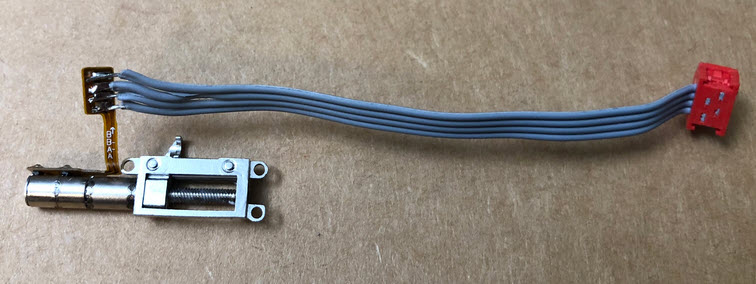
The project idea started spotting some mini stepper motors available for sale on the internet:
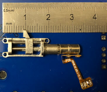
It would be cool to use these motors to move something like a LED pixel to create a special effect. The motors are able to move an item for distance of 10 mm, with a time of about 2 second.
No data sheet, no specs, except ‘mini stepper motor @5V’. It seems that these motors are used for motorized cameras as in the Chinese Vivo V15. The ones on the market are probably sur-plus motors not used in production.

So could these motors be used to move LED pixels?
SmArtWall
The idea is to create a ‘wall of smart pixels’, with gave the starting project the name ‘SmArtWall’. Leoni Etter explored that idea and created the first working concept.
A first test PCB used the stepper clock project as base, using the same LED, motor driver and NXP K02 as microcontroller. Below the first test PCB to test the motor and LED positioning.
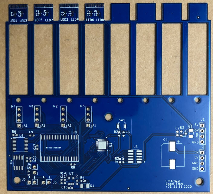
Each pixel uses two SK6812 (side) RBW LEDs. Motor holders are PLA 3D printed, with two 5 mm laser cut acrylic pieces:
The acrylic pixels have a cutout. Inside the cutout the LEDs are placed, and the motor can move the pixel forward and backward.
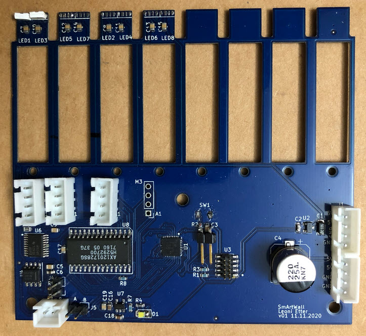
That concept worked :-). After that, a new PCB with a total of 8 motors was built:
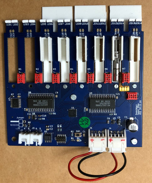
In this design, two LEDs are used to light up each pixel:
Connecting the motors to the PCB has been a challenge. One first attempt was to use a cable and connector:
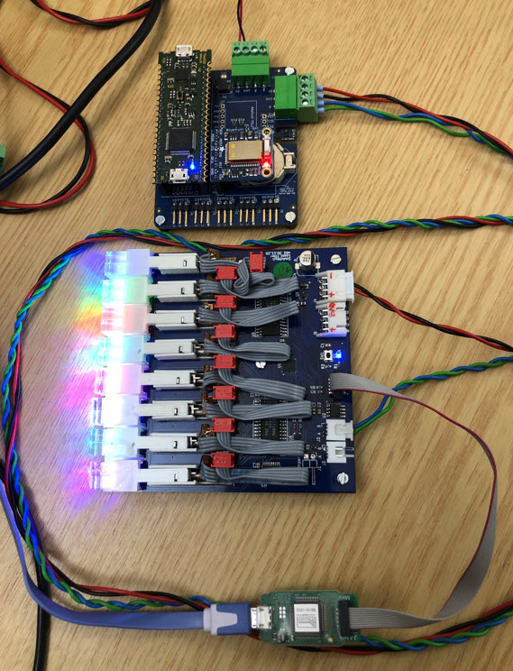
Below with the PCB with the connected motors:
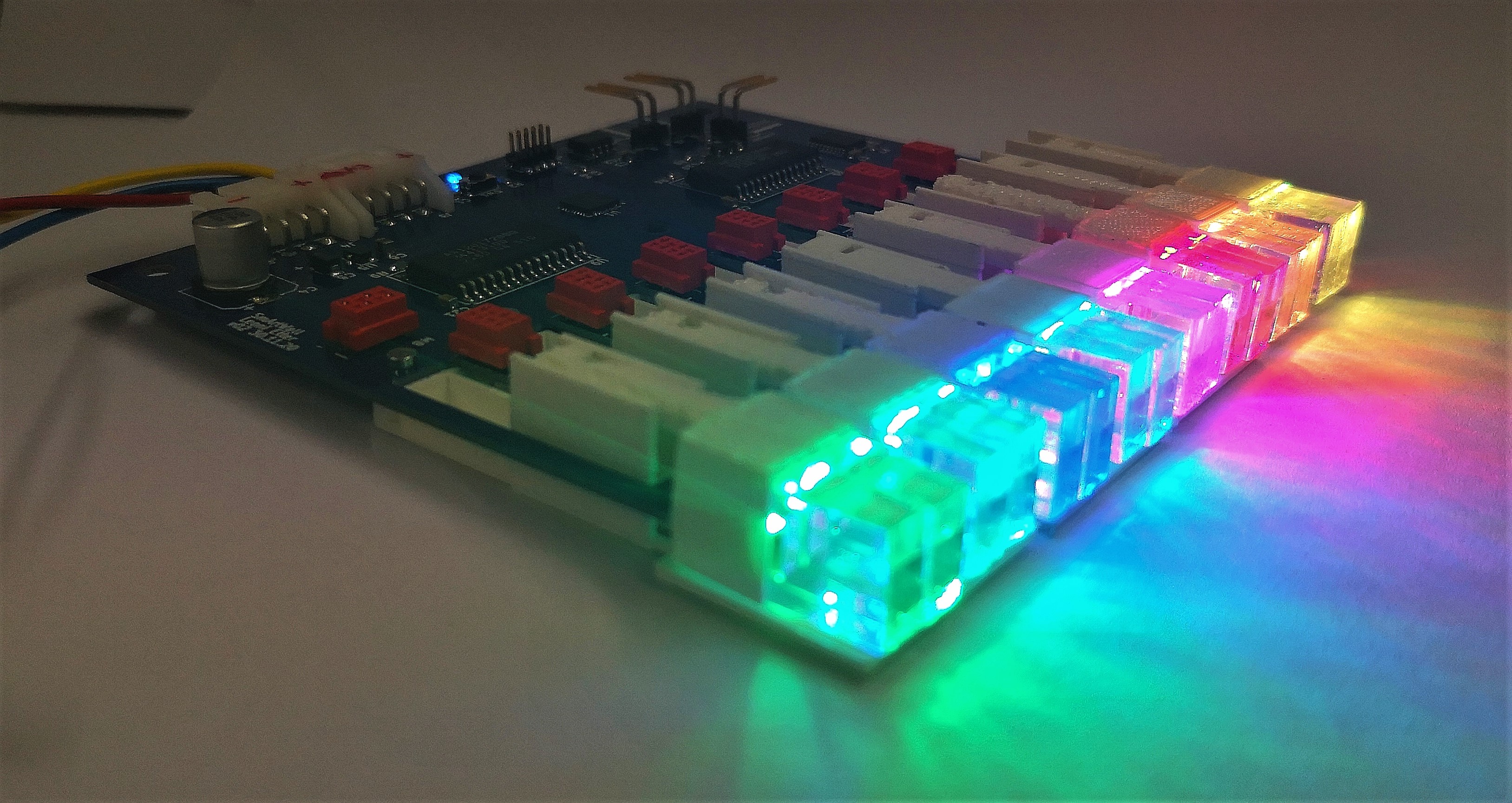
Tests with the pixels were looking good. Below a single pixel, 10 mm ahead of all other pixels in the row:
There were some concepts to detect the end position of the motor. At the end, the simplest thing was just to initialize the motor with some number of forward/backward steps to find the zero position.
Similar to the MetaClockClock project, the board can be controlled over RS-485. Below a tinyK22 is controlling the pixel position plus the color:
The idea was to stack and combine multiple units. As shown below, the wiring and cable gets in the way:
In summary: The concept works, and pixels can be moved. But the used motor driver was not powerful enough to move the pixels in a reliable way, so the stepper motor driver needs to be changed. Additionally the motor connection with the cables was very painful and needed a lot of assembly time. Additionally the space between the boards need to be optimized.
Motor Driver
The next step was to find a better stepper motor driver for the project. Jan Rohrer evaluated the STM STSPIN220 low voltage stepper motor driver. The STSPIN220 is small (3x3mm) in a VFQFPN package.
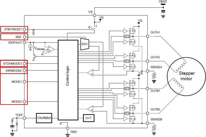
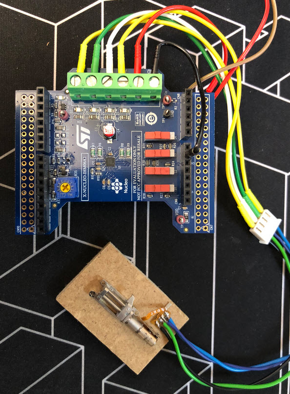
First tests were using an evaluation board from STM:
This stepper motor driver works with 5V, with full-step, half-step and quarter-step modes. Below the schematic used for testing the driver.
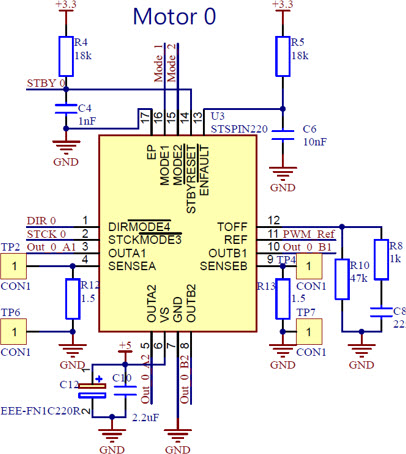
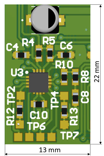
Space needed for the driver circuit was a concern, but it is possible to fit the electronics inside an area of 22×13 mm:
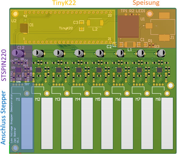
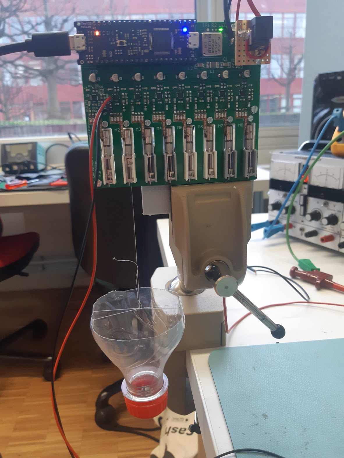
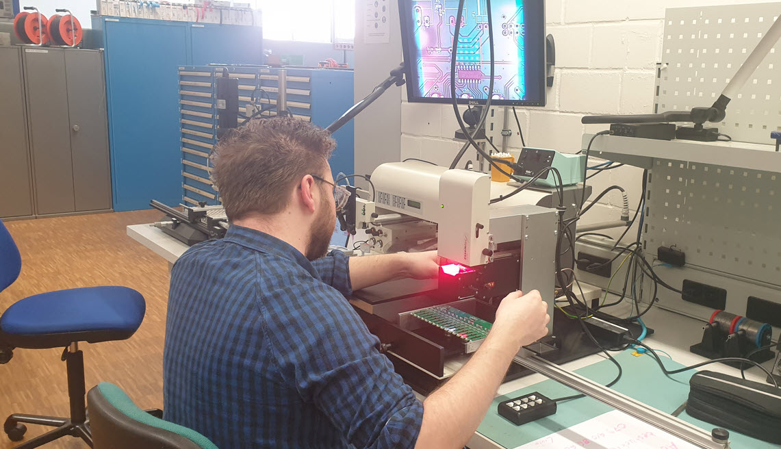
To measure the performance of the driver, a test board with 8 drivers and motors was built. The firmware runs on a tinyK22 board running FreeRTOS using Eclipse/MCUXpresso as IDE.
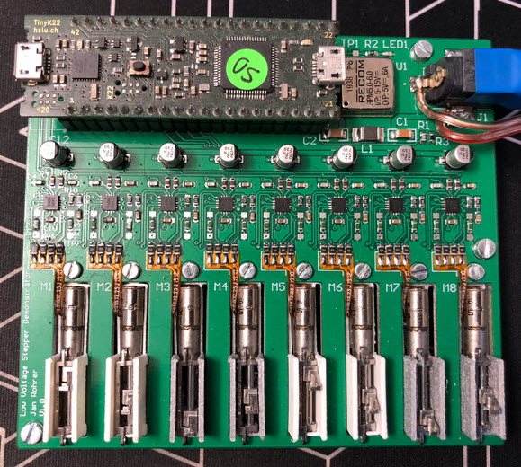
Instead using a connector and cables, the motor flex-PCB cable is connected to the PCB using 0-Ohm resistors, making it much easier and clean:
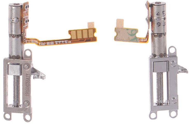
But, what we had to find out later: there are different connector types for the motors!
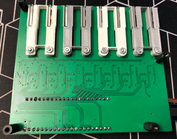
Backside of the PCB with the 3D printed motor holder:
Testing showed that a single stepper motor is able to pull up to 500 g of weight without loosing steps:
Tests were done with different current limit settings:
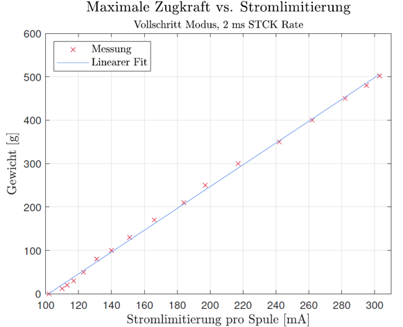
Clearly, with more current, the motor is more powerful. But drawing 500 mA at 5V for each motor is a lot. Tests showed that a limit of 250 mA would be a good compromise, especially as the motor has to stall at the end positions to zero the position without extra sensor.
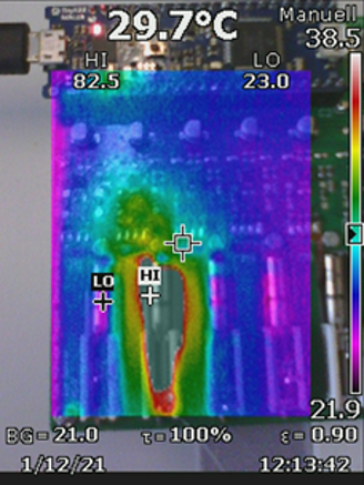
Thermal management was a concern: Passing a constant current of 250 mA through the motor heats it up, up to 80 °C after 1 minute. The motor driver IC remains at around 35 °C.
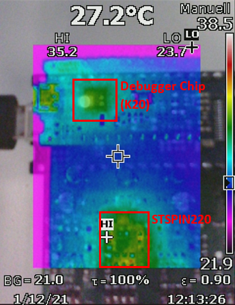
If using in ‘normal’ mode with only moving the motor around 10% of the time with a limit of 250 mA proves that both motor and driver IC can stay around or below 35 °C:
As a result: The STSPIN220 was selected as stepper motor driver for the project. Unfortunately, right after the decision the ‘silicon shortage’ kicked in. It was impossible to get the ICs, so this had put this project to a temporary halt.
On the plus side: we had found a way to reduce the space needed by each motor and pixel by directly connecting the motor signals to the PCB.
Moving Pixel Clock
We have now the idea, the motors, the motor drivers and the pixels. The final step was to combine everything, for a larger demonstrator. And what could be better than building a ‘Moving Pixel Clock’? It was Livio Stadelmann who accepted the challgene.
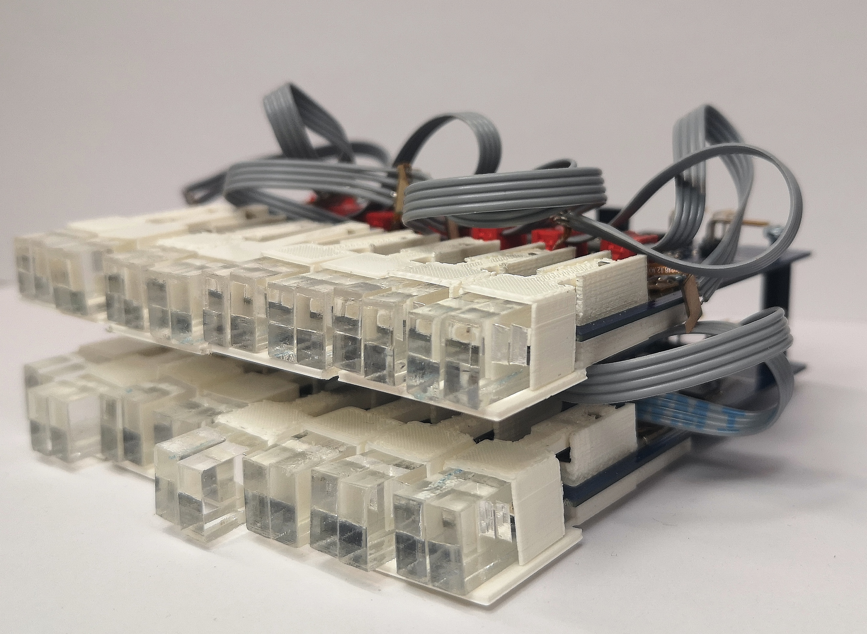
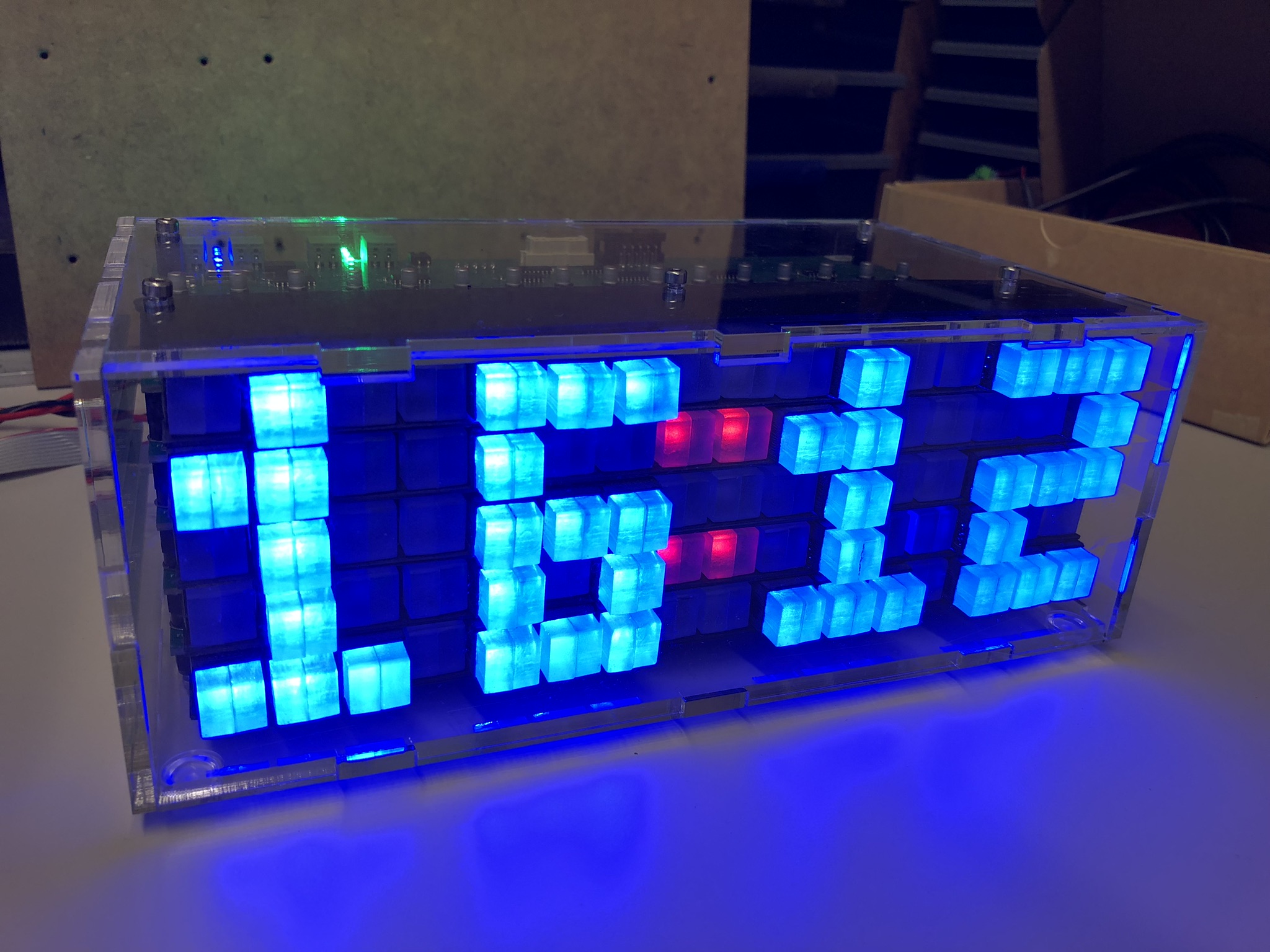
To be able to display a time, a matrix of 5×16 pixels had to be built:
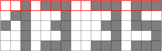
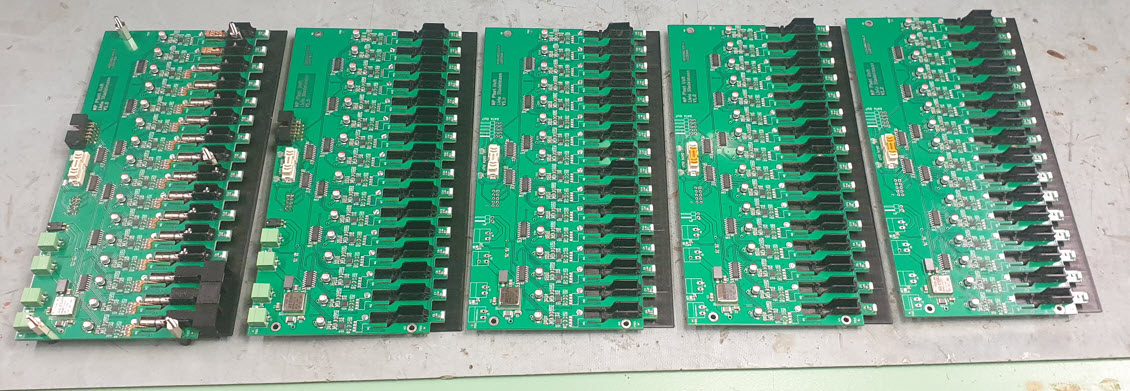
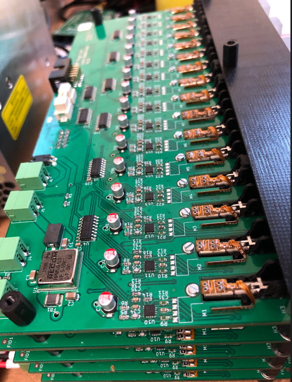
The matrix has 5 layers with 16 pixels in a row, with stacked PCBs each for 16 pixels in a row:
The stacked units are connected, and data is sent through shift registers.
Providing enough power was a concern. In the worst case (all LEDs on, every motor moving, …), the 80 pixels need up to 100 Watt. Because of this a 12V power supply is used, with 5V DC-DC converter on each board (logic and LED supply):
To deal with the different motor types, the PCB has special slots to mount motors in different ways.
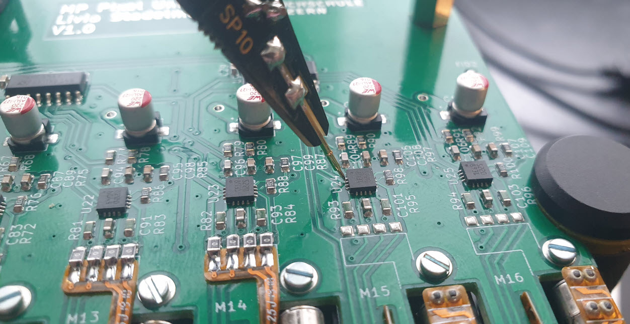
Below a picture how the motor flex-PCB is connected on the bottom side of the PCB:
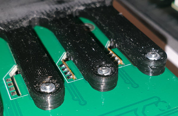
Here with the ZOR (Zero Ohm Resistor) method:
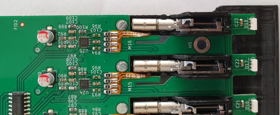
The picture below shows both types of motors:
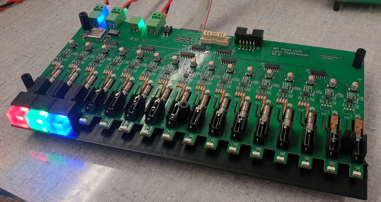
The number of LEDs has been reduced from two to a single LED for each pixel:
Pictures from the assembly phase:
As main controller a tinyK22 is used (similar to the MetaClockClock project), with optional wireless interface:
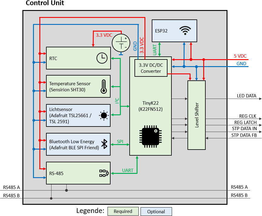
Below is a controller board without the optional components. The flat cable provides the signals to the shift registers:
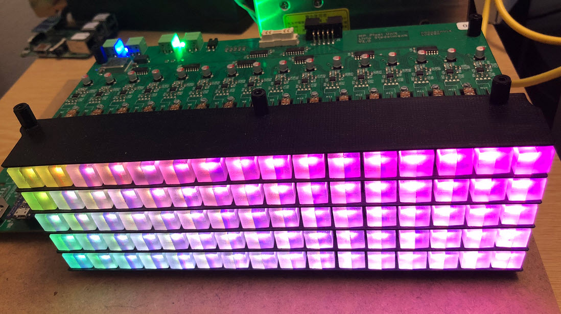
The 5 PCBs are stacked on top of each other and interconnected:
Below a view of the top PCB, with the 3D printed parts:
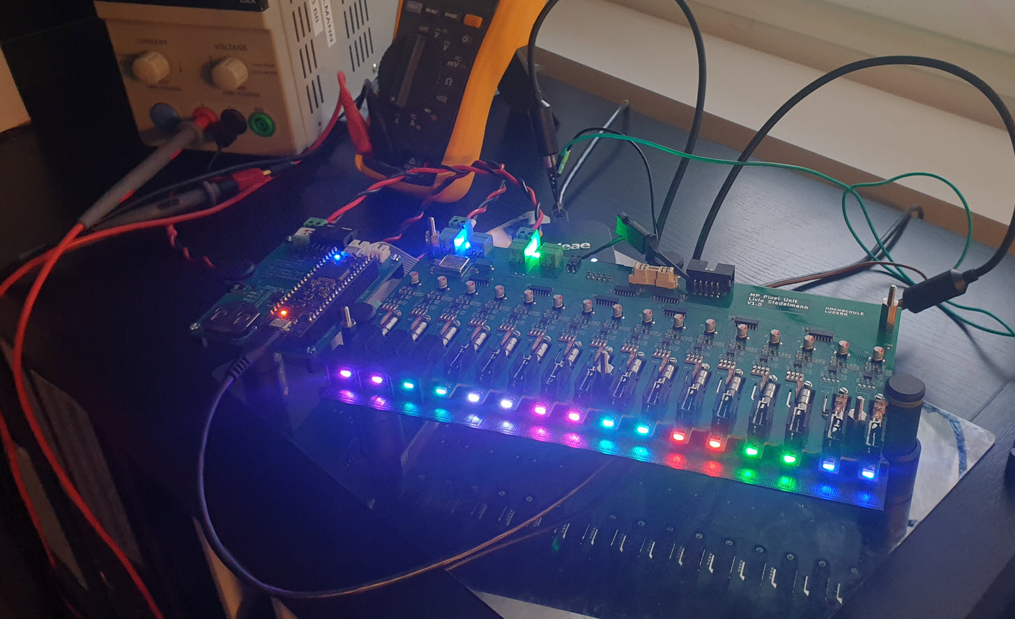
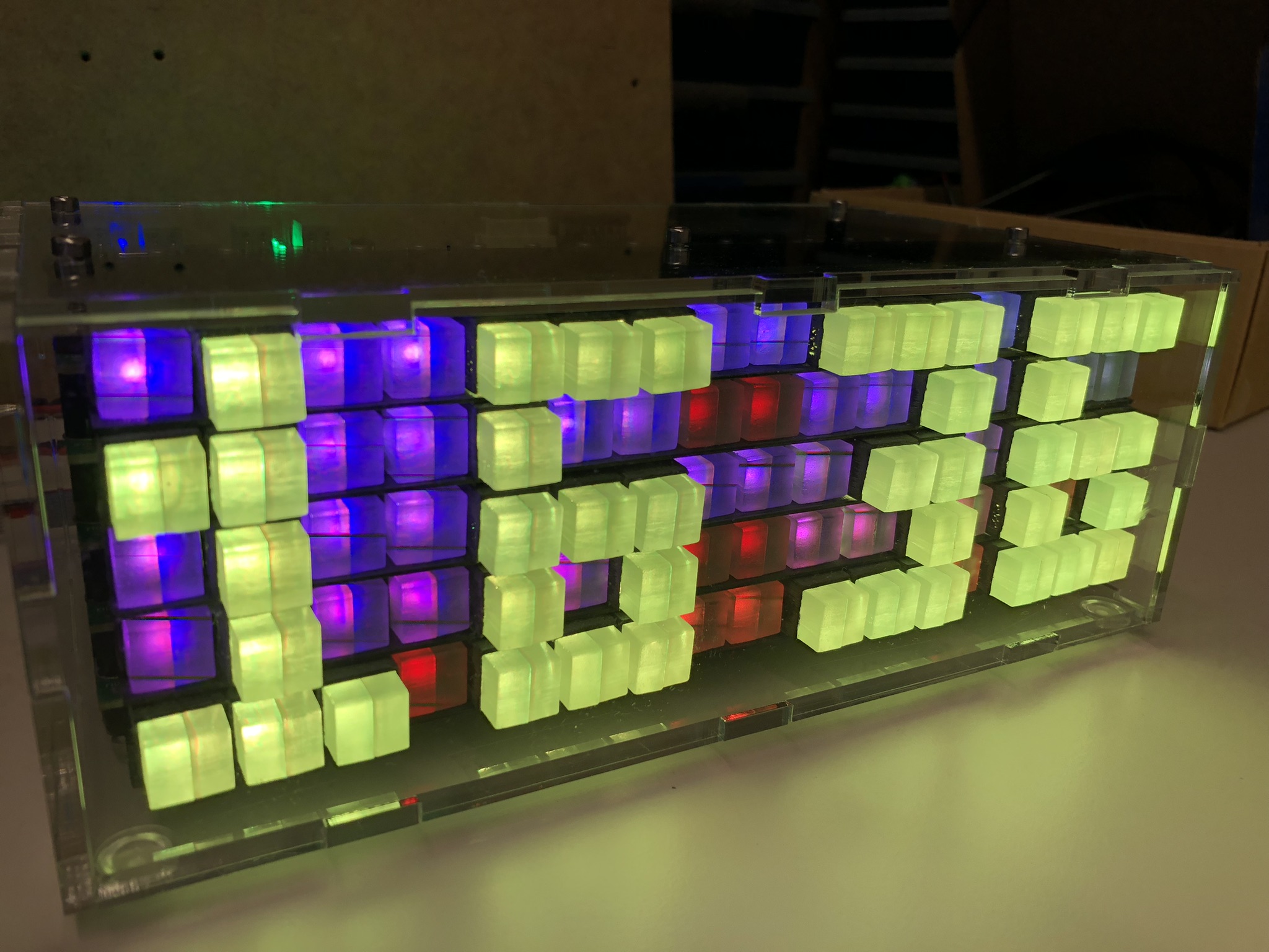
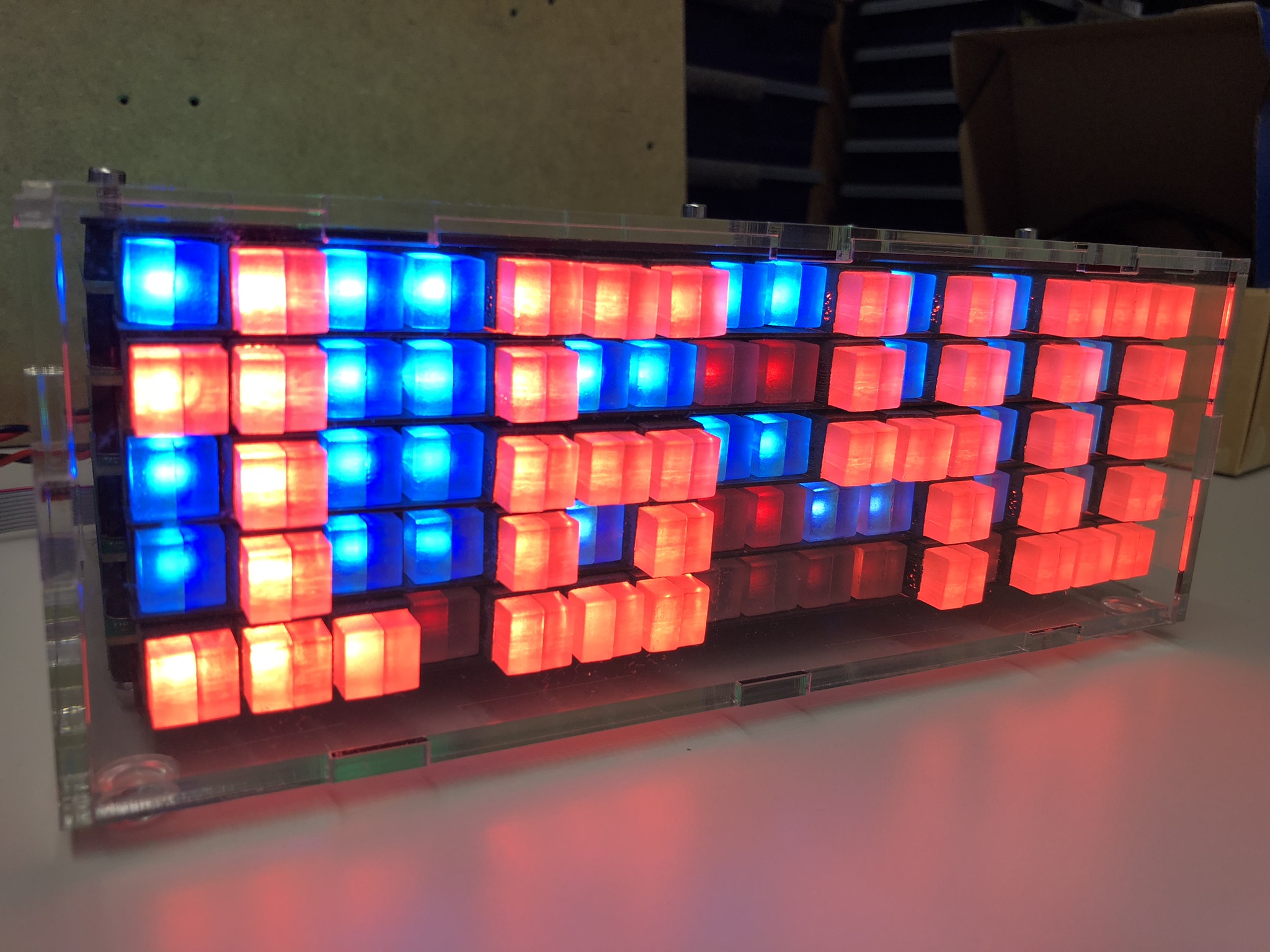
Testing different color effects:
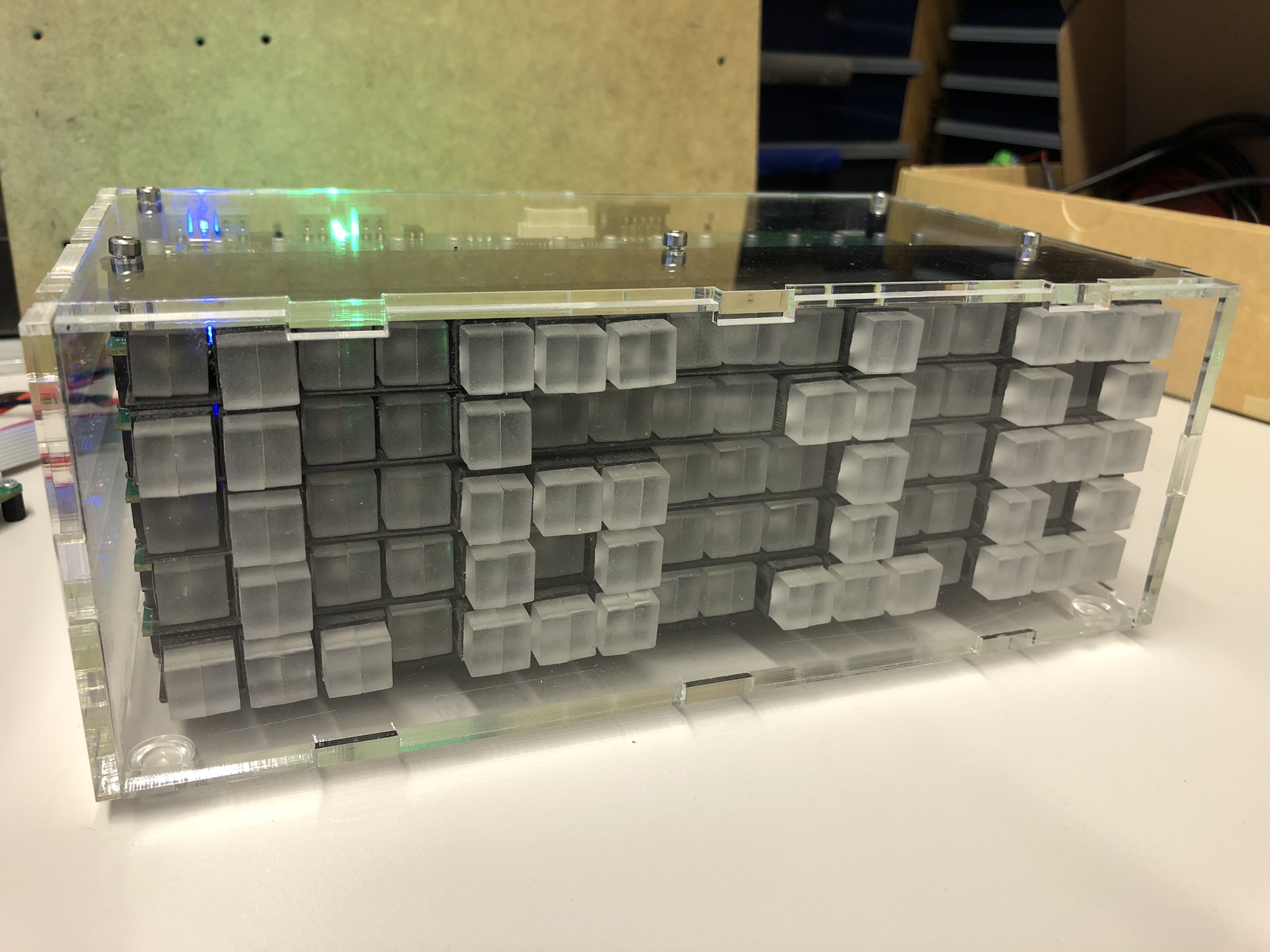
For a better effect, the pixels have been ‘frosted’:
Each pixel had to be sandblasted:
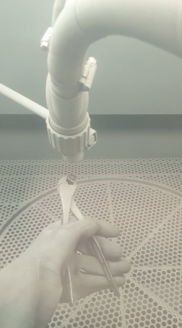
With this, the pixels make a much better appearance and glow on the sides:
Another concern was the noise of the moving motors. Obviously the noise is higher if all motors are moving. With only few motors moving, it is noticeable in a very silent room, but considered OK otherwise.
Below is the clock mode with moving pictures in action:
Enclosure
To protect the circuit and moving parts, I have created a laser-cut enclosure make of 4 mm PMMA:
Firmware
The software runs on the ARM Cortex M4F (tinyK22, NXP K22FN512), is written with Eclipse/MCUXpresso as IDE in C/C++ using FreeRTOS. It features an automatic and command line mode, with many ways to drive and change the matrix. Below is a list of command line commands (USB CDC):
--------------------------------------------------------------
tinyK22 Master
--------------------------------------------------------------
McuShell                  ; Group of McuShell commands
  help|status             ; Print help or status information
McuRTOS                   ; Group of McuRTOS commands
  help|status             ; Print help or status information
  tasklist                ; Print tasklist
McuArmTools               ; Group of McuArmTools commands
  reset                   ; Performs a software reset
  help|status             ; Print help or status information
McuTimeDate               ; Group of McuTimeDate commands
  help|status             ; Print help or status information
  time [hh:mm:ss[,z]]     ; Set the current time. Prints the current time if no argument
  date [dd.mm.yyyy]       ; Set the current date. Prints the current date if no argument
  dateToSec <datetime>    ; Convert date/time int UNIX timestamp (seconds after 1970)
  secToDate <secs>        ; Convert UNIX timestamp to date/time
McuExtRTC                 ; Group of McuExtRTC commands
  help|status             ; Print help or status information
  time [hh:mm:ss[,z]]     ; Set the current time. Prints the current time if no argument
  date [dd.mm.yyyy]       ; Set the current date. Prints the current date if no argument
stepper                   ; Group of stepper commands
  help|status             ; Print help or status information
  enable <xyz> y|n        ; Enable or disable a stepper
nvmc                      ; Group of NVMC commands
  help|status             ; Print help or status information
  flags <val>             ; Set flags
McuMinINI                 ; Group of McuMinINI commands
  help|status             ; Print help or status information
  read <f> <s> <k>        ; Read a key from a section in a file
  write <f> <s> <k> <v>   ; Write a key with value to a section in a file
  delkey <f> <s> <k>      ; Delete a key in a section of file
  delsec <f> <s>          ; Delete a section in a file
ini                       ; Group of flash ini commands
  help|status             ; Print help or status information
  dump                    ; Dump data information
  erase                   ; Erase data information
McuFlash                  ; Group of flash ini commands
  help|status             ; Print help or status information
  dump <start> <size>     ; Dump memory data
  erase <addr> <size>     ; Erase memory at address
rs                        ; Group of RS-458 commands
  help|status             ; Print help or status information
  addr <addr>             ; Set RS-485 address
  send <text>             ; Send a text to the RS-485 bus
  sendcmd <addr> <cmd>    ; Send a shell command to the RS-485 address and check response
  log on|off              ; Log RS-485 bus activity to McuLog
McuUart485                ; Group of RS-485 commands
  help|status             ; Print help or status information
  clear <flags>           ; Clear UART ISR flags
matrix                    ; Group of matrix commands
  help|status             ; Print help or status information
  stepper status          ; Print stepper status information
  test                    ; Test the stepper on the board
  rgb pixel <xyz> <rgb>   ; Set pixel color
                          ; <xyz>: coordinate, separated by space, e.g. 0 0 1
                          ; <md>: mode (cc, cw, sh), lowercase mode letter is with acceleration control for start/stop, e.g. Cw
                          ; <d>: delay, 0 is no delay
  r <xyz> <s> <d> <md>    ; Relative step move (comma separated)
  a <xyz> <s> <d> <md>    ; Absolute step move (comma separated)
  q <xyz> <cmd>           ; Queue a 'r' or 'a' command, e.g. 'matrix q 0 0 0 r 90 8 cc', (comma separated)
  exq                     ; Execute commands in queues
  lastError               ; Check remotes for last error
  waitidle                ; Check remotes for idle state
  sendcmd <cmd>           ; Send a command to all boards
  park on|off             ; Park the motor(s)
clock                     ; Group of clock commands
  help|status             ; Print help or status information
  on|off|toggle           ; Enable or disable the clock
  24h on|off              ; Show time in 24h (17:35) or 12h (5:35) format
  park on|off|toggle      ; Turns clock off and moves to park position, ready to power off
  period <minute>         ; Clock update period in minutes (>0)
  seconds on|off          ; Show seconds
  border on|off           ; Show clock with border
ledclock                  ; Group of magnet/hall sensor commands
  help|status             ; Print help or status information
  color digit <color>     ; Set digit color
  color dot <color>       ; Set dot color
intermezzo                ; Group of intermezzo commands
  help|status             ; Print help or status information
  on|off|toggle           ; Turn intermezzos on, off or toggle
  delay <sec>             ; Intermezzo delay in seconds
  fade <sec>              ; Intermezzo color fade in seconds
  <nr>                    ; Play Intermezzo (0-4)
demo                      ; Group of demo commands
  help|status             ; Print help or status information
  on|off                  ; Enable or disable the Sm(Art)Wall demo mode
SHT31                     ; Group of SHT31 commands
  help|status             ; Print help or status information
neo                       ; Group of neo commands
  help|status             ; Print help or status information
  clear all               ; Clear all pixels
  set all <rgb>           ; Set all pixel with RGB value
  set <lane> <pos> <rgb>  ; Set pixel in a lane and position with RGB value
pixel                     ; Group of moving pixel commands
  help|status             ; Print help or status information
  zp all                  ; Move all to zero position
  zp <xyz>                ; Move a single pixel to zero position (comma separated)
shiftreg                  ; Group of ShiftReg commands
  help|status             ; Print help or status information
  inv status              ; Print inversion information of each motor.
  inv <motor> <inv?>      ; Set direction inversion of a motor. (true = inverted / false = not inverted)
  set <motor> <val>       ; Set motor value (3bits: clk, dir, stdby)
  move <motor> <steps>    ; Move motor with steps (forward/backward)
You can find the files on GitHub.
Summary
It took longer than expected from the idea to the finished project: from the idea to the first working prototypes, solving all kind of problems up to the final project. Last but not least finding the time for this article and description. I think the result is very special and rewarding, and is mesmerizing watching the pixels moving.
Many thanks to Leoni Etter, Jan Rohrer and Livio Stadelmann for their contributions!
Happy moving 🙂

Once again a great post.
LikeLike
Thank you!
LikeLike
Very cool idea and a nice write up too.
LikeLike
Thank you!
LikeLike
I am very happy that you finished the project! Now many art-wall programming projects can be done 😉
Greetings to Lucerne
Leoni
LikeLike
Hi Leoni,
Many thanks for your contributions to the project, nice to hear from you! There are some ideas how to reduce the space needed by the driver PCBs (could be smaller by about 20%). That way it would be easier to mount it on a wall. The clock is now working for months and so far everything is working fine. Additional pixel animation patterns are in the work too, beside of creating a laser-cut enclosure.
LikeLike
Pingback: The Moving Pixel Clock #Projects #ARM @McuOnEclipse « Adafruit Industries – Makers, hackers, artists, designers and engineers!