
Well let’s face it, modern microcontrollers are complicated. The User Manual for the LPC55S69 has 1148 pages (Rev 1.3) and that does not include any of the electrical characteristics – see the Datasheet (129 pages) nor does it include the details around the core or instruction set (see ARM documentation) . So there is a lot of technical information to read, and don’t get me started on the pin multiplexing… Well actually, do get me started on the pin multiplexing because that is my focus this week.
This week I turned my attention to writing a very simple example project in MCUXpresso IDE to run on the ARM Cortex® M33 core inside the LPC55S69. As in previous weeks I am again using the LPC55S69-EVK from NXP. My plan is to use this board every week but I have learned recently a few details about a new ultra-low-cost board. It’s going to be AMAZING and I’ll share more details with you when I can.
The project will use a CTIMER timer output with PWM to change the brightness of the green LED on the board. An 10 ms interrupt from the MULTI-RATE TIMER will ramp the brightness up and down so that the LED pulses. And lastly, an interrupt from the USER switch on the board will generate a PINT interrupt and this is used to mask the LED output.
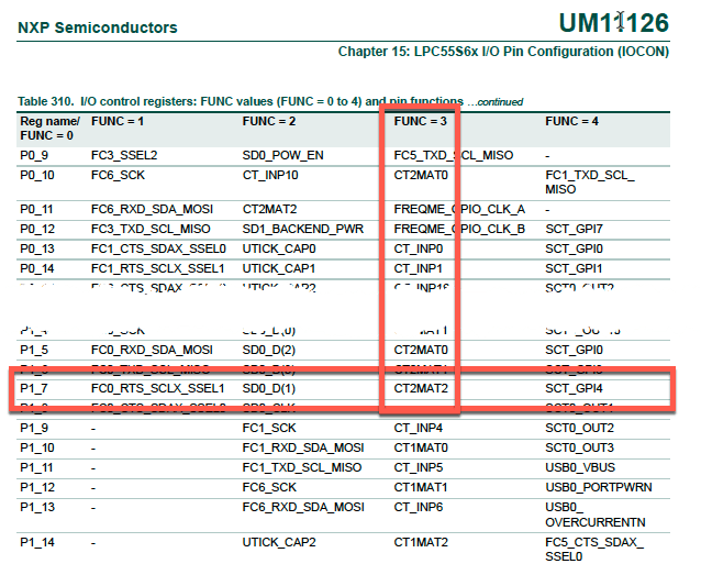
With the increasing complexity of the microcontroller and the extensive pin multiplexing, we will introduce the Pin Multiplexing “Config’ tool within MCUXpresso IDE> This gives us a very quick way of selecting the function for each pin of the microcontroller from the list of available functions. In the video I’ll show you how find out where the Green LED is connected on the LPC55S69-EVK and then control it in hardware from the match register in the CTIMER. We’ll find that the CTIM2MAT2 function is the 3rd alternate function for the GPIO pad PIO1_7 and quickly configure it with the Pins Config tool.
The video on my embeddedpro® YouTube channel is not a programming tutorial. So I’ll show you how to use the MCUXpresso tools to generate the project, but you’ll need some software to make it all happen. The video shows you how to cut and paste the code into MCUXpresso IDE and so you should get your LED pulsing without too many challenges. Use this link to download a text file with the source code:
https://mcuoneclipse.com/wp-content/uploads/2019/09/lpc55s69_pwm_example-3.pdf

And for your interest, I normally use a heart-beat indication like this on every project that I develop just so that there is a visual indication of activity on the board. And by changing the parameters I can make a range of LED patterns that provide more information about what the software is up to. So I use a faster pattern of blinking to warn me about a fault.
To be fair, there are quite a few online tutorials about the MCUXpresso IDE Pins Config tool. And so you can watch my video here…
… but I ‘borrowed‘ some tips from NXP and Erich at the following locations:
Eclipse MCUXpresso IDE 10.1 with integrated MCUXpresso Configuration Tools
Tutorial: Muxing with the New NXP Pins Tool
NXP Pins Tool: Clock Gates and Controlling the Bits
https://www.nxp.com/pages/mcuxpresso-config-tools-overview:TIP-MCUXPRESSO-CT-OVERVIEW
Please let me know how you get on, and don’t forget to share the information with your friends. And come back next Monday when I’ll cover the Clocks Config tool in MCUXpresso IDE in some more details.

Hi Mark,
Thanks for your effort.
What is the device revision of your mcu on the board?
The LPC55S6x HLQFP100 package has the following top-side marking:
•First line: LPC55S6x
•Second line: xxxxxxxx
•Third line: zzzyywwxR–yyww: Date code with yy = year and ww = week.
–xR: Device revision 0A or Device revision 1B
Cheers,
Hans
LikeLike
Hi Hans, thanks for your question. The LPC55S69-EVK is a Rev A1 board (I received it early in the summer) and the package is marked – third line:
sSD19200A
So this is an A0 revision device. Also, the quality of the laser etching on the third line is extremely poor. I’d say that the NXP logo is over-exposed whereas the third line is very hard to read.
LikeLike
Pingback: LPC55S16-EVK: how fast does it go? How much current does it take? | MCU on Eclipse
A typo is present on line 54 for the definition of CTIMER_CLK_FREQ, but in my environment, the kCLOCK_CTimer2 does not exist and seems to be named kCLOCK_Timer2. The LED lights after 40secs but does not increase in luminosity. I have a Revision A1
LikeLike
Thanks Emmanuel, and I am pleased that you are using these tutorials. You’ll observe that, at exactly 7 minutes into the video, I am using SDK version 2.6.2. This genuinely does have the typo kCLOCK_Tmier2, and you’ll see it at line 481 of the source module fsl_clock.h in SDK 2.6.2. That was version 2.1.0 of fsl_clock.h.
The current SDK is version 2.7.2, fsl_clock.h is at revision 2.3.1, and there has been a lot of tidying up. That clock name is now renamed kCLOCK_Timer2 – as you said.
Regarding the LED not working, I suspect that the clock source for the multi-rate timer MRT is not configured properly. If you place a breakpoint at the start of MRT0_IRQHandler, does the breakpoint get hit ‘immediately’ – after 10ms – or does it take ~40s for the breakpoint to be hit?
LikeLike
Hi Mark,
I have an interrupt happening every 10ms (and not 40s), though I suspect possibly a difference in the PWM control due to the SDK version I use, and I suspect the LED is getting lighting when the PWM duty cycle is 100%, but would be off for the other duty cycle, explaining the flash happening at the end.
Do you agree on my conclusion ?
LikeLike
Hi Emmanuel, I investigated this behaviour today, and now understand the issue. The driver has been rewritten since I wrote the material. If you change the following line, it will be OK now:
#define CTIMER_CLK_FREQ CLOCK_GetFreq((clock_name_t)kCLOCK_CoreSysClk)
The driver takes the name of the AHB clock – kCLOCK_CoreSysClk – now, instead of the divided-down timer clock kCLOCK_Timer2 (or kCLOCK_Tmier2 in that version of SDK).
LikeLike