
I will always take the same approach when I receive a new embedded board: firstly I want to see how quickly I can get it up-and-running, then I want to see what it does “out-of-the-box” and finally I want to find out if the board is “useful”. Does it have some features that will inspire me for new projects??
The NXP LPC55S16-EVK has some great features – CAN-FD, dual USB and a high performance Cortex M33 microcontroller, running at 150 MHz. I have an idea to use the LPC55xx series as the basis for a Weather Station. But this is only feasible if the chip has a low power consumption and can run for weeks on a small battery.
Time to run some test code and get my digital multimeter out…
Let’s start with a quick refresher on the power rails for the LPC55S16. As you can see from the EVK schematic extract, the LPC55S16-EVK has three power rails supplying the microcontroller, MCU_VBAT, MCU_VDD and MCU_VDDA.
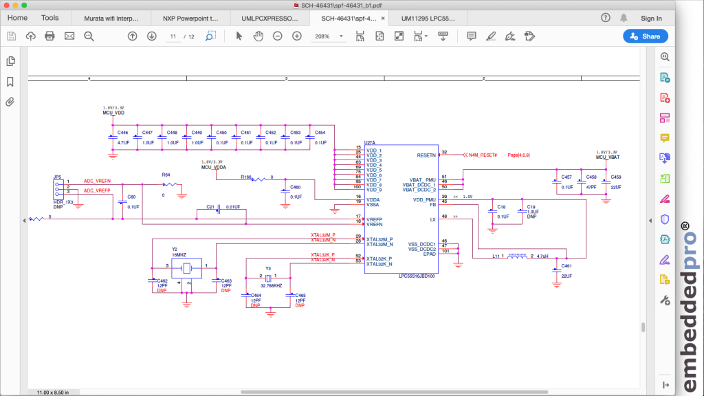
Sorry. “As you can see” is a bit optimistic. Here are the jumpers where we can measure the three rails. Conveniently, NXP have provisioned the board with three headers, each populated with a jumper. To measure any of the rails, I can remove the header and put my multimeter in circuit to measure the current.

- MCU_VDD: default jumper settings on LPC55S16-EVK have this set to 3.3 volts. The supply rail drives the IO pads on the microcontroller. The current consumption is proportional (I need to read section 13.1 of the Preliminary Datasheet) to the switching speed of the IO pins.
- MCU_VDDA: supplies the internal analog circuits, ADC etc.
- MCU_VBAT: default jumper settings on LPC55S16-EVK have this set to 3.3 volts. The supply rail drives the DCDC converter and power management unit (PMU) on the microcontroller. The current consumption is proportional (maybe??) to the operating frequency of the microcontroller.
If we want to understand the power consumption of the LPC55S16, we need to add together the current consumption into each of these supply rails.
Current consumption at 150 MHz, CAN-FD loopback test
Since CAN-FD is a new feature on LPC55S16 I wanted to run some test code from the LPCXpresso55s16 Software Development Kit (SDK v2.7.0). The CAN-FD loopback test is ideal, because the CAN signals are looped back into the microcontroller and I did not have a second EVK to act as a slave receiver. I noticed that the operating frequency was set to 150 MHz since the code example sets up the clock with function call BOARD_BootClockPLL150M(). If you’ve read my previous blogs you’ll know that I never trust the operating frequency of a microcontroller until I’ve measured it. In this test, I enabled the clock out pin CLKOUT in the Pins Config tool, and set the CLKOUTDIV to divide by 250. Assuming a real main clock of 150 MHz, I would expect to see (150/250) = 0.60 MHz (600 kHz) on the CLKOUT pin.
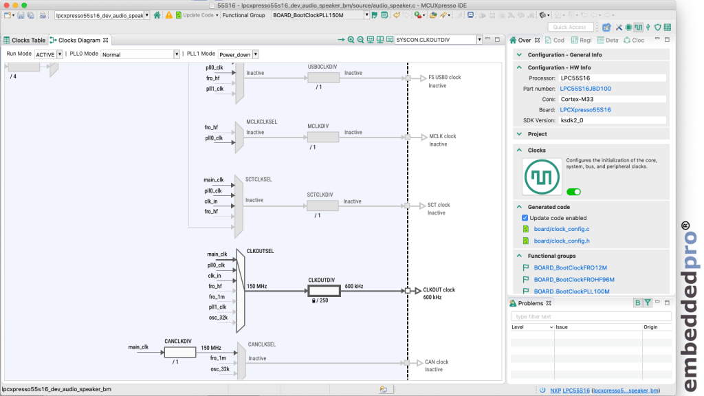
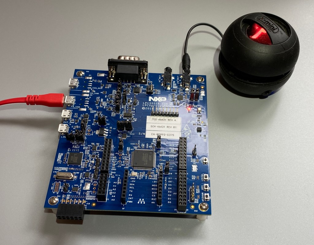
Sure enough, when I ran the CAN-FD loopback demo, I was able to measure 600 kHz on the CLKOUT pin. You’ll see that I have the speaker connected to the board, ready for the next test.

We’re all engineers, so I’d expect you to shout “That’s not 600 kHz: it’s 601 kHz” and you would be correct. In this example the PLL generating the 150 MHz man clock is referenced from the internal 12 MHz free-running oscillator FRO12M and so is not exactly 12 MHz, meaning that the output of the PLL is not exactly 150 MHz. And I would not fully trust the accuracy of an uncalibrated, €50 Digital MultiMeter. However, I am satisfied that the core is running with a main clock of 150 MHz.
So, what about the current consumption?
The demo does not use analog circuitry, nor does it drive the IO pads of the microcontroller and so I was not able to measure any current in the MCU_VDDA or MCU_VDD rails (JP20, JP21). However, there was current drawn in the MCU_VBAT supply. Here is my DMM connected to JP22 with the microcontroller consuming 7.54 mA at 150 MHz.
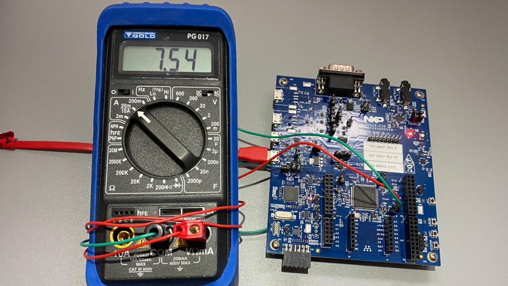
That is a little higher than the Idd figure from the preliminary datasheet, but I still find it extraordinary that this microcontroller is so power efficient. I’m always a bit suspicious when I see “xx uA/MHz” figures in embedded system marketing information. But here is a real-world, 50 uA/MHz with the microcontroller doing something useful (CAN-FD loopback code).
Current consumption at 96 MHz, USB speaker demo
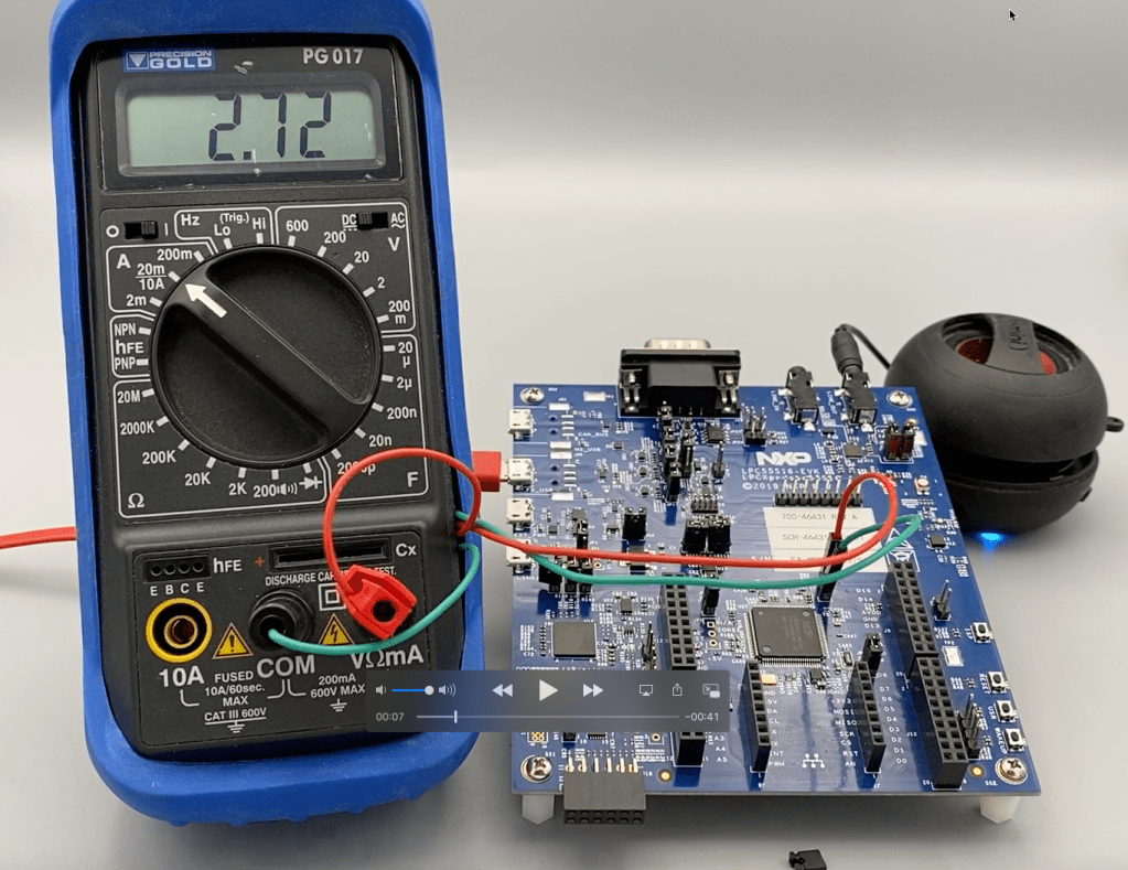
Built into the LPCXpresso55s16 SDK v2.7.0 is a USB device audio demo lpcxpresso55s16_dev_audio_speaker_bm. In this demo, the LPC55S16-EVK is flashed with a demo that turns it into an external speaker. When connected to a host computer, the board is recognised as a USB audio device. The host can then stream audio to the LPC55S16-EVK, and the audio is output (through the Cirrus Logic codec and LINE_OUT 3.5mm socket) into an external speaker. My setup is like this:
Of course the demo works as advertised (I tested it on my Mac) and you can see it operational in the video accompanying this blog:
The Cortex M33 core is running at 96 MHz in this example.
So what about the current consumption?
I made similar current measurements, and this time there was current flowing into the MCU_VDD connection to the LPC55S16. Remember that there is USB data coming into the chip, and it is also DMA-ing audio data out to the codec. So we expect some current in the IO pad drivers. I measured 2.72 mA across JP20 MCU_VDD.
I also measured approximately 4 mA in the MCU_VBAT rail, and again this is the supply for the DCDC converter and internal low-drop-out regulators on the chip. Therefore, in this USB audio demo, with the LPC55S16 operating at 96 MHz, the whole application is running in single-digit milliamps. Extraordinary.
Wrap up
LPC55S16-EVK was very easy to set up, and the SDK example projects downloaded and ran without any issues. I was able to test both the USB Full Speed and CAN-FD peripherals, use the Pins and Clock Config tools in MCUXpresso IDE to make some simple changes to the examples, and make some simple current consumption tests. And I was most impressed with the low current consumption figures for this microcontroller. What about the Weather Station idea? I’m now certain that either LPC55S16 or LPC55S69 will be featuring in my weather station project. Just not certain about the flash memory requirement just yet. Perhaps I’ll start on LPC55S69 and transition to LPC55S16 when the memory footprint becomes more clear.
You’ll find the full video analysis of the LPC55S16-EVK hosted at the embeddedpro YouTube channel, and I’ve embedded the video for you 4 paragraphs above this one.
That’s it for now. Next time, I’m going to introduce you to a brand new, ultra-small, ultra-low cost Cortex M33 development board. I’ve been working with it for a few months now, and it will be ready for launch in early May 2020. It’s currently my favourite embedded platform… but of course you’d expect me to say that! See you next time.

Pingback: Testing the NXP LPC55S16-EVK dev board @McuOnEclipse @NXP « Adafruit Industries – Makers, hackers, artists, designers and engineers!
Now that so many MCUs have on-board buck regs (though this might be a first for NXP) don’t you think its time to update the standard metric of ‘uA/MHz’ to something that truly represents power, like ‘uW/MHz’. 7.54mA is impressively low but the current to the core (running ~1.2V) will be between 2 and 3 times this value due to the buck reg. 20mA at 150MHz doesn’t sound nearly as impressive does it?
LikeLike
Good inputs, Richard. I feared that I would be called out for using marketing numbers on a technical blog site!!
I’m not a big fan of any ‘derived’ units like uA/MHz or uW/MHz as they don’t really tell us anything (other than the fab process that the chip is built with). MHz doesn’t tell us how much work the core gets done (compare CoreMark figures for M0/M0+/M3/M4/M23/M33/M7) and normally the current consumption figures in the datasheet is qualified for sram/flash/while()/all peripherals off and doesn’t reflect real-world use-case. So I don’t particularly recognise uA/MHz as an engineering value: it is more popular in the marketing community.
Regarding the “core” current being higher, yes of course. But I’m from the ‘old school’ practical world where I care about the overall current into the device, since this is the figure I need for the power supply (or battery) design. Your example highlights the advantage of using the uW/MHz metric since it represents both the current and voltage for the core. Things are more complex because (certainly for NXP) the DCDC module is implementing dynamic voltage scaling, based on the operating frequency of the core.
LikeLike
Fair enough that you consider uA/MHz to be marketing fluff. I have found it useful to track improvements in efficiency in NXP’s lines of M0/M4s but initially was caught off-balance by the 32uA/MHz metric for the M33 until I delved deeper into the datasheet. The previous line of M4 I was keeping tabs on (LPC54114) only managed about 100uA/MHz but then again it could do that down to 1.62V, not just at 3.3V.
The other slightly misleading thing about the conditions for the 32uA figure is it applies only to flash with lots of wait states. Running from SRAM its a bit less efficient, but presumably crunches way more Coremarks?
LikeLike
Richard, fully agree with your comment about misleading numbers in market. It is general problem. Standard for this measurement is missing, but I agree with Mark that common measurement is what is the drain from power supply (battery).
In fact LPC55 devices are really efficient in power.
As you can see in DS at 3V:
CoreMark at 96MHz from flash (7WS) device consume 3.2mA (34uA/MHz)
CoreMark at 96MHz from SRAM (0WS) device consume 3.4mA (36uA/MHz)
CoreMark at 150MHz from flash (11WS) device consume 4.9mA (33uA/MHz)
CoreMark at 150MHz from SRAM (0WS) device consume 5.8mA (39uA/MHz)
LikeLike
Dear sir welcome. This board LPC55S16
Suitable for vfd Inverter drive control board .
LikeLike
The LPC55S16 features the advanced motor control timer SCTimer. This is suitable for a variety of drive applications, but you will need to determine if the frequency range is suitable for your VFD inverter. You might start here: https://www.nxp.com/design/training/mcu-tech-minutes-exploring-the-sctimer-feature-on-lpc5500-series-mcus:TIP-NXP-TECHMINUTES-SCTIMER-FEATURE
LikeLike