
I don’t know if it is the same for you. But for me, configuring the pins on these new ARM microcontroller is a challenge: Most pins can do multiple functions, such as be used as I²C, UART or GPIO pins.
Configuring the pins ‘by hand’ is difficult, error-prone and usually the first thing I need to do for a new project/device. NXP developed a new tool for this task and previewed it at FTF 2016. It is available now both as web (online) and desktop (locally installed) tool. At FTF it was possible to play with an engineering release: time to get my hands on the public release :-). And as more and more student projects will start using that tool for their boards, I better have a tutorial for it :-).

Desktop Version of Pins Tool
Overview
The pins tool is used to configure the pins (muxing, pin assignment, electrical properties, …). It uses a graphical user interface for this, and the output is C source and header files I can use in C/C++ applications. It does the ‘muxing’ (more about this later), and just the muxing.
Pin Muxing and Application Flow
In a typical application, the code runs out of reset, runs through the startup code (set stack pointer, initialize memory and ANSI library), then calls main() (which does pin muxing, clock configuration and driver and middleware initialization) then calls the application code:
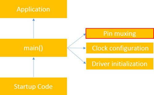
Application Startup Sequence
The pins tool does one single thing: pin muxing.
The output of the pins tool is what exists today in typical Kinetis SDK V2 projects as the pin_mux.c and pin_mux.h files.
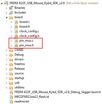
Pin Mux in SDK V2.0 Project
💡 At FTF it was clear that the Pins tool is just the first tool of a larger set of tools, and there will be similar tools for clock configuration and driver and middleware afterwards.
The device drivers (UART, SPI, USB, I²C, …) are provided by the SDK (see “First NXP Kinetis SDK Release: SDK V2.0 with Online On-Demand Package Builder“) which includes middleware like FreeRTOS or the USB stack.
Comparing with Processor Expert, the Pins Tool is similar to the ‘PinSetting’ component in Processor Expert:

Processor Expert Pins Setting Component
That Processor Expert component does pin muxing and configuration:

Processor Expert Pins Setting Component Properties
Muxing
So why do I need such a Pins tool? Most, if not all pins on a modern microcontroller can be used for different functionality (UART, GPIO, I²C, SPI, …). That feature is implemented on the device with a multiplexer, and the common term for doing this is called ‘muxing’ or ‘muxing the pin(s)’. That muxing is a common source of mistakes and errors because the data sheets are not always crystal clear.
For example the MK64FN1M0VLL12 on the FRDM-K64F board has 100 pins which need to be configured:

MK64FN1M0VLL12
I have seen several board designs failing with boards produced, only to find out in the software that a pin cannot be used as intended because of some side conditions. That’s why I recommend my students to do the muxing and software *first*, and then do the board layout based on the muxing.
Pins Tool
NXP showcased the new Pins Tool at FTF 2016 in Austin/TX (see FTF-DES-N1958, FTF-DES-N1960 and FTF-DES-N1957) as part of the Kinetis Expert suite of configuration tools. It exists as web (online) version and as a desktop application on a host (Windows, Mac, Linux). I tried out only the Windows version so far. The Desktop installers can be downloaded from http://www.nxp.com/ksdk.
Online version of Pins Tool
Desktop Version of Pins Tool
The functionality is the same with very minor differences e.g. for menus and file handling. Personally I prefer the desktop version as I’m travelling by train a lot with no internet connection. And because my internet connection is not that fast, the desktop version suits better for me.
Installation
For the desktop version installers available in the download section of http://www.nxp.com/ksdk, there is a offline (around 130 MByte which includes Java runtime in case it is installed on the host) and an online (0.5 MByte) version. The difference is that the online version will fetch the installation data from the internet during installation, while the offline version has that already included.
💡 I recommend the ‘offline’ version especially for slower internet connections. For both versions, the device data is not included in the download.
For the desktop version on Windows, both a 32bit (x86) and a 64bit (x64) version is provided. Make sure you download the one matching your host OS. There is a .pkg for Mac OS X and both dep and rpm packages for Linux (64bit).
Launching the Tool
The web version of the tool is started using the button on http://kex.nxp.com/:
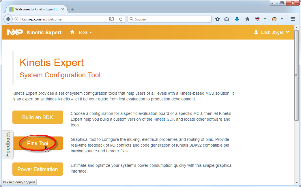
Starting Web Version of Pins Tool
For the desktop version there is a shortcut available:
Desktop Shortcut
Configuration
As the Kinetis SDK (see “First NXP Kinetis SDK Release: SDK V2.0 with Online On-Demand Package Builder“), the tool needs a ‘configuration’. Basically this specifies the device, package and all other needed information for the tool.
New Configuration with the Desktop Tool
Starting the Desktop tool, it asks to create a new configuration first. I can pick a board or a device/processor:
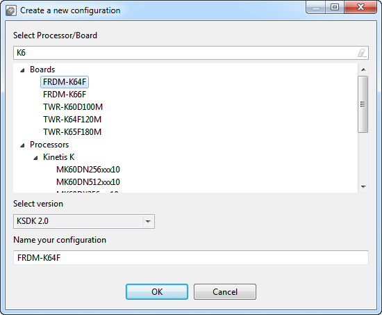
Creating New Configuration
When creating a configuration for a device the first time, it downloads the data from the internet:
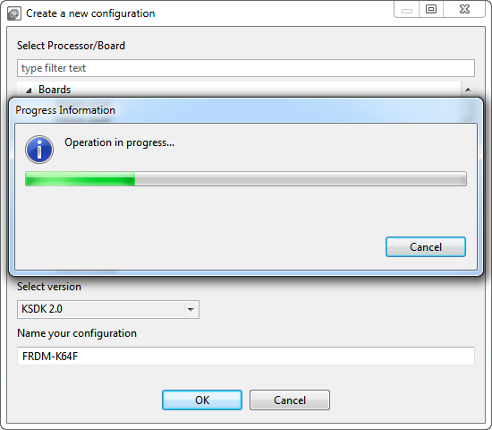
Downloading Data
💡 The device data is loaded from the internet when I’m creating a new configuration for a new device. On my Windows 7 machine the data is stored in C:\ProgramData\NXP.
A new configuration is created anytime with a menu:
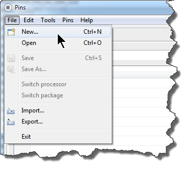
Creating New Configuration
Unlike the web version which works directly with the data in the cloud, configurations are stored/loaded on the disk with the desktop tool. The configurations are stored as .mex (XML) files.
New Configuration with the Web Tool
In the web version, use the ‘Tools’ menu to select Pins tool:
Pins Tool Menu
If using the tool the first time, it might not have configuration yet:

No Configuration Created Yet
To create a new configuration:
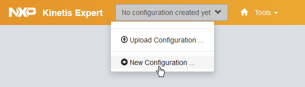
Select New Configuration
Then select the device or board from the list. Optionally I can give it a different name:
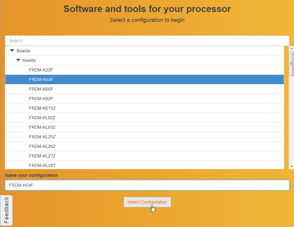
Select New Configuration
The Pins tool will create code for the SDK 2.0. If I do not have the SDK yet, I need to build one first. In this tutorial I’m using the Kinetis Design Studio as IDE on Windows:
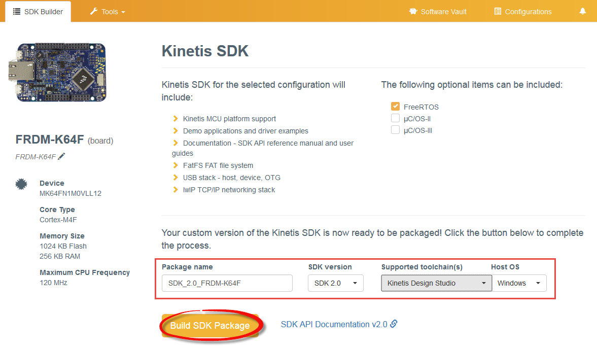
Build SDK
I get a notification when the new build is available:

New Configuration Available in the Software Vault
Click on the download icon to download the file:
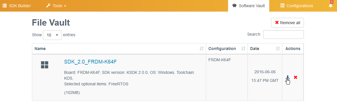
Download from the Vault
It will ask for a license agreement (does anyone ever read that full text?), then store the file on the disk.
I place and extract all my SDK packages into a common folder (e.g. C:\nxp\KSDK), but that’s up to you.
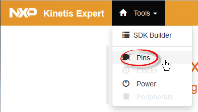
As I have now a configuration, I switch back to the Pins tool with the Tools menu:
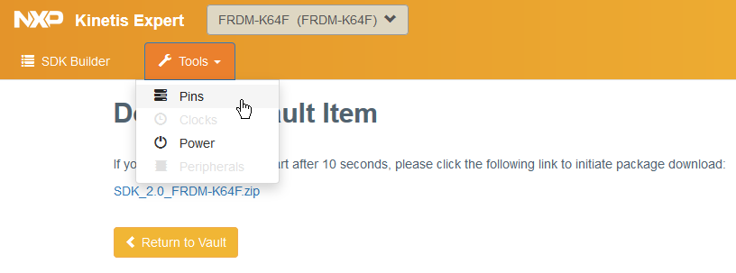
Selecting Pins
Main View
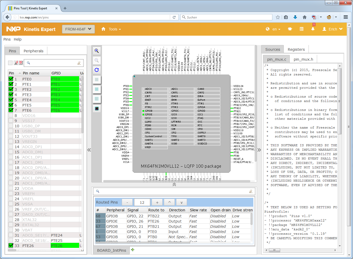
This shows me the first view:
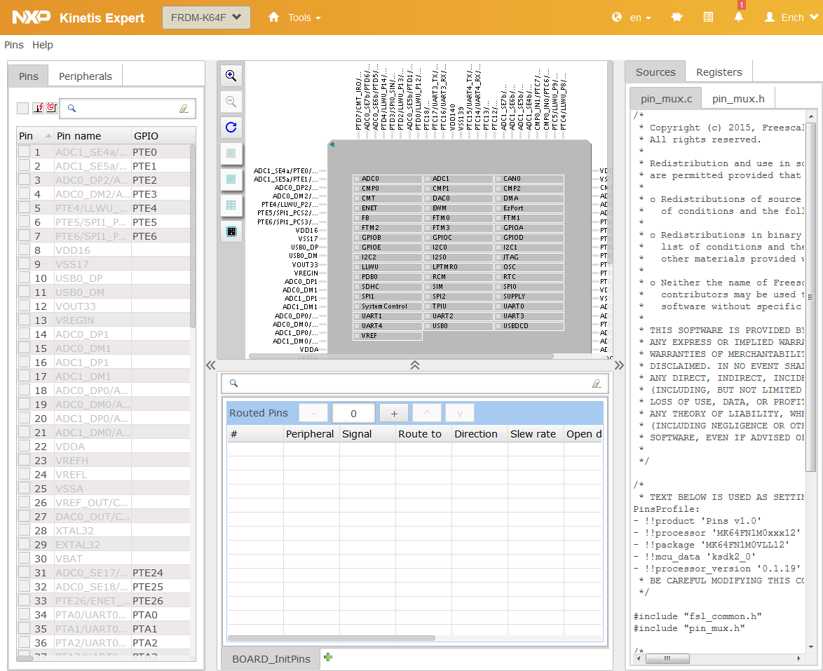
Initial View
On the left: the list of pins and peripherals. In the middle is the CPU package with the routed pins, and on the right hand side the generated source code and registers information.
Menus
Source code is generated automatically in the background, but I have a menu to generate it too:
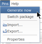
Pins Menu
I can change the package (pin out) with the ‘Switch package’ menu, or I can use the button in the package view:

Changing the Package Option
The help menu gives access to release notes and documentation resources:
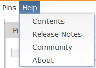
Help Menu
Localization
Both the web and desktop tool do support multiple display languages: English and Chinese. In the web version it is a menu entry:
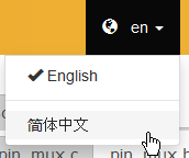
Switching to Chinese (Web Version)
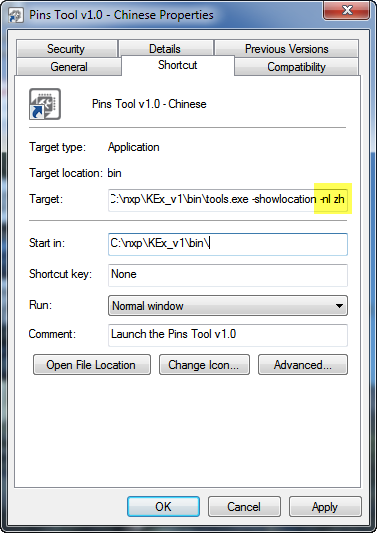
In the Desktop version it uses the locale of the host machine. I can force a language in the startup parameter of the executable:
-nl <language>
With <language> as
- en: English
- zh: Chinese
💡 There is another way changing the language by modifying the .ini file, as explained in the release notes.
Starting Desktop Tool in Chinese

Desktop Pins Tool in Chinese
Example: Muxing RGB LEDs
In the following example I’m going to configure three pins on the FRDM-K64F board which are connected to the RGB LED. If you have a different board, then you need to check the schematics. The one for the FRDM-K64F looks like this:

FRDM-K64F RGB Schematics
- Red LED: PTB22
- Green LED: PTE26
- Blue LED: PTB21
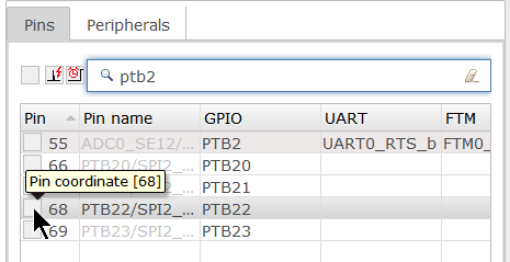
In the ‘Pins’ view I can filter for the pins I’m looking for:

Filter for Pins
I click on the pin check box to mux it:
Click on the pin to mux it
As the pin has several options, I get a dialog from where I can select the GPIO function. At the end, if that muxing works out, it turns green:

Muxed Pin
The selected pin gets added to the list of routed pins:

List of Routed Pins
That’s just one way to configure pins. Another way is to select the PTE26 from the Peripherals view:

Selected PTE26
Another fast way to configure a pin is to use the tabular Pins view. It is like an Excel sheet, and I can simply click on a cell to mux it:

Click on Pins Cell
And it is possible to export that table view in a CSV file format for Excel, using Export > Export the Pins in CSV from the Pins menu (web version) or from the File menu (Desktop version):
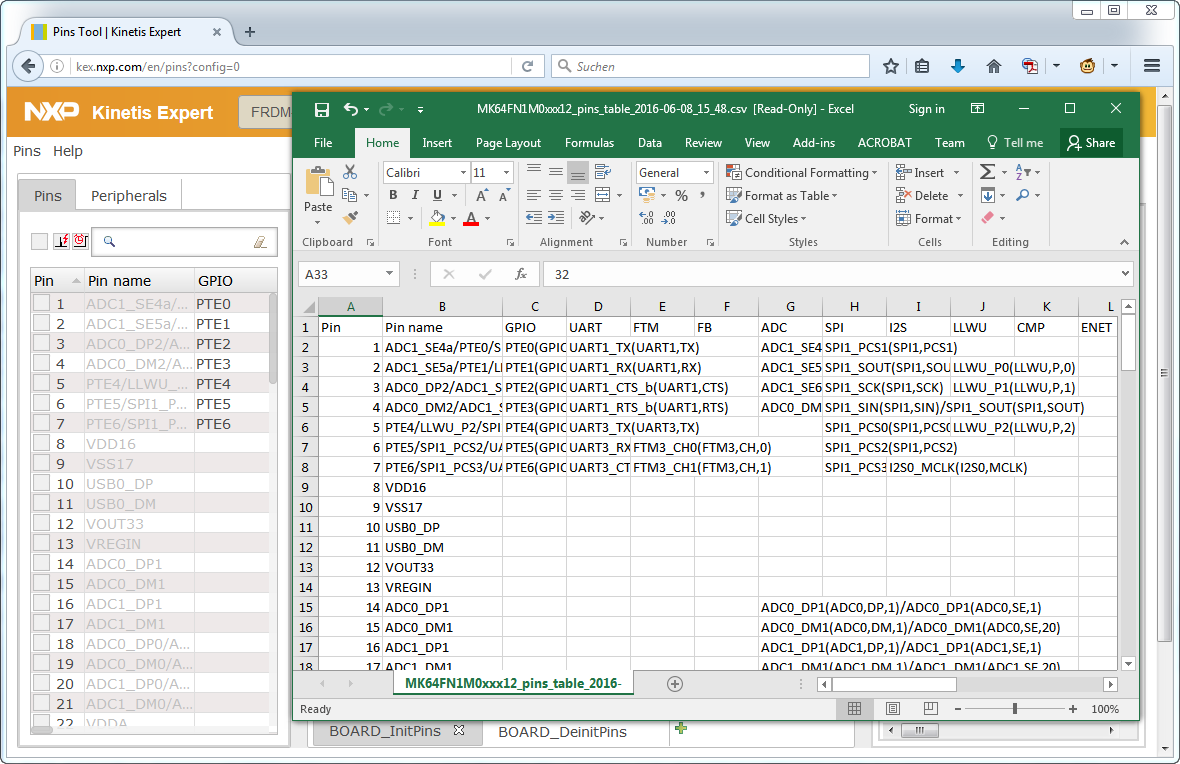
Pins Export as CSV
There is a filter check box I can use to only show the configured pins:
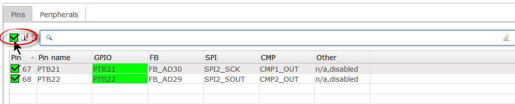
Filtered Pins
Because usually not all pins have interrupt capabilities, there is a filter for this too:
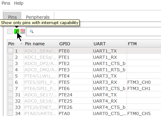
Interrupt filter
Similar to that, there is filter for pins which can wake up the device from low power mode:

Low Power Wacke-up Pins
Selecting a pin or a group of pins is highlighting it on the package so I can see where it is located:
Highlighting
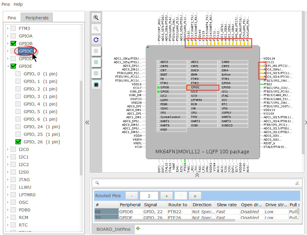
I can add/remove pins with clicking on the pin or peripheral block in the package view too:

Add and remove pins with the package view
The pin gets added to the list of routed pins. As I have assigned just the pin number, I can change the settings there too. For example to assign GPIOB function to pin number 67:
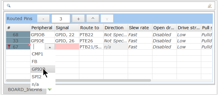
Changing Settings In Routed Pins View
The context menu allows me to change the items in the list or change the order:
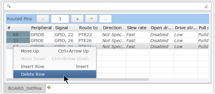
Context Menu in Routed Pins View
The same way I can use the toolbar icons to add/remove/move items in the list:
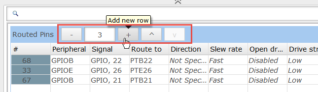
Routed Pins Toolbar
All three LED pins are output pins, so I set the direction:

Setting Direction
So I have them all set as output pins:

All set to output
Registers View
In the registers view I can filter for the configured registers and inspect what registers are affected. The ‘Set Value’ shows the configured value, and the ‘Reset value’ the default/out-of-reset’ one:
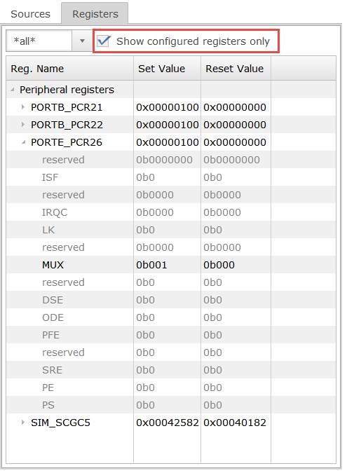
Registers View with configured registers
Sources
While I’m doing changes, it generates the code for it in the background. I can check the sources in the sources view on the right side:
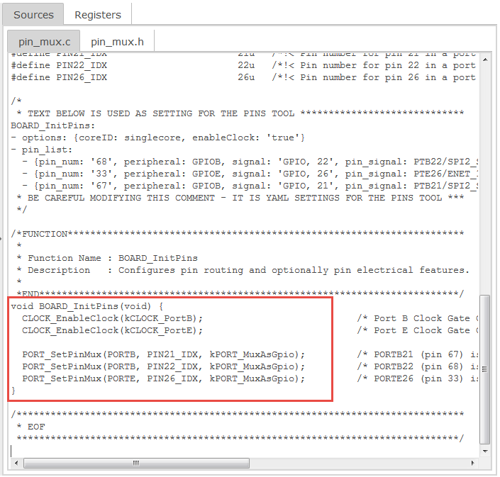
Generated Code to Initialize the Pins
Yet Another Markup Language?
One interesting thing in the generated sources are comments like this one:
/* * TEXT BELOW IS USED AS SETTING FOR THE PINS TOOL ***************************** PinsProfile: - !!product 'Pins v1.0' - !!processor 'MK64FN1M0xxx12' - !!package 'MK64FN1M0VLL12' - !!mcu_data 'ksdk2_0' - !!processor_version '1.0.0' * BE CAREFUL MODIFYING THIS COMMENT - IT IS YAML SETTINGS FOR THE PINS TOOL *** */ /* &amp;amp;nbsp;* TEXT BELOW IS USED AS SETTING FOR THE PINS TOOL ***************************** BOARD_InitPins: - options: {coreID: singlecore, enableClock: 'false'} - pin_list: &amp;amp;nbsp; - {pin_num: '66', peripheral: GPIOB, signal: 'GPIO, 20', pin_signal: PTB20/SPI2_PCS0/FB_AD31/CMP0_OUT, direction: OUTPUT} &amp;amp;nbsp; - {pin_num: '67', peripheral: GPIOB, signal: 'GPIO, 21', pin_signal: PTB21/SPI2_SCK/FB_AD30/CMP1_OUT, direction: OUTPUT} &amp;amp;nbsp; - {pin_num: '33', peripheral: GPIOE, signal: 'GPIO, 26', pin_signal: PTE26/ENET_1588_CLKIN/UART4_CTS_b/RTC_CLKOUT/USB_CLKIN, direction: OUTPUT} &amp;amp;nbsp;* BE CAREFUL MODIFYING THIS COMMENT - IT IS YAML SETTINGS FOR THE PINS TOOL *** &amp;amp;nbsp;*/The comment mentions YAML: a data serialization language. So the settings are stored inside the sources which is a neat way, because that way the settings end up in a version control system with the source files.
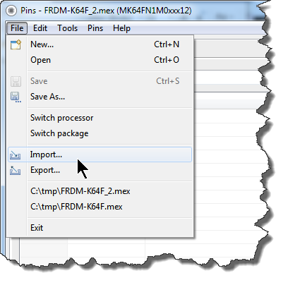
And indeed, I can import source files with YAML using the Import menu:
File Import
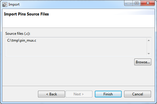
Then I can import one or more .c files with YAML comments in it:
Import Pins Source File
So all what I need to get the data imported into the Pins tool are such YAML content in source files. Which means I can pass my students pin_mux sources with YAML content, they can load it into the tool and extend/change the content with the tool and store it back. Or I could write-up a YAML generator tool which would create YAML files as input for the tool. Or NXP could give their examples with YAML content in it, and I can simply take the example source files and do my stuff with it. Up to the point to change the YAML content ‘by hand’ (e.g. to change a pin assignment) and then have the tool to create the source code for it. I think that’s a very neat way to deal with data and settings.
Clock Gate Enable
You might notice that there is some clock enable code at the start of BOARD_InitPins():
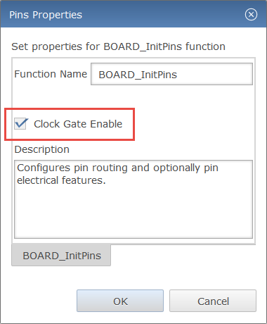
&amp;amp;nbsp; CLOCK_EnableClock(kCLOCK_PortB);&amp;amp;nbsp;&amp;amp;nbsp;&amp;amp;nbsp;&amp;amp;nbsp;&amp;amp;nbsp;&amp;amp;nbsp;&amp;amp;nbsp;&amp;amp;nbsp;&amp;amp;nbsp;&amp;amp;nbsp;&amp;amp;nbsp;&amp;amp;nbsp;&amp;amp;nbsp;&amp;amp;nbsp;&amp;amp;nbsp;&amp;amp;nbsp;&amp;amp;nbsp;&amp;amp;nbsp;&amp;amp;nbsp;&amp;amp;nbsp;&amp;amp;nbsp;&amp;amp;nbsp;&amp;amp;nbsp;&amp;amp;nbsp;&amp;amp;nbsp;&amp;amp;nbsp; /* Port B Clock Gate Control: Clock enabled */ &amp;amp;nbsp; CLOCK_EnableClock(kCLOCK_PortE);&amp;amp;nbsp;&amp;amp;nbsp;&amp;amp;nbsp;&amp;amp;nbsp;&amp;amp;nbsp;&amp;amp;nbsp;&amp;amp;nbsp;&amp;amp;nbsp;&amp;amp;nbsp;&amp;amp;nbsp;&amp;amp;nbsp;&amp;amp;nbsp;&amp;amp;nbsp;&amp;amp;nbsp;&amp;amp;nbsp;&amp;amp;nbsp;&amp;amp;nbsp;&amp;amp;nbsp;&amp;amp;nbsp;&amp;amp;nbsp;&amp;amp;nbsp;&amp;amp;nbsp;&amp;amp;nbsp;&amp;amp;nbsp;&amp;amp;nbsp;&amp;amp;nbsp; /* Port E Clock Gate Control: Clock enabled */This can be turned off in the settings behind the menu Pins > Properties menu:
Clock Gate Enable
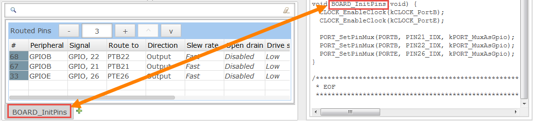
The same dialog specifies the ‘Function’ name which is shown in the ‘tab’ below for the ‘Routed Pins’ and which is used in the generated source code:
Function Name
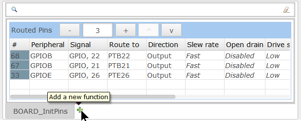
‘Functions’ are treated as independent muxing functions. The BOARD_InitPins() is the default function used by the SDK. But I can add my own functions:
Add New Function
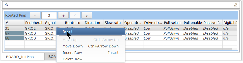
I can give it my name e.g. with the ‘Rename’ context menu on the tab. One use case would be do de-init pins and put them back to the ‘Reset’ values. For this there is a ‘Reset’ menu on a pin:
Put to Reset Values
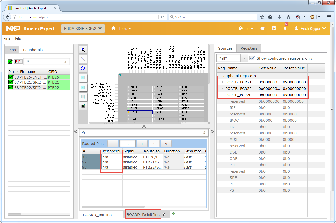
With this, I have a BOARD_DeinitPins() function which puts the values back to the reset values:
Putting Pins back to Reset Values
Using it with Kinetis Design Studio
The tool generates source files compatible with the NXP Kinetis SDK V2.0.
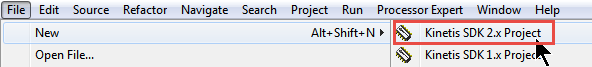
I can create new a new SDK v2.0 project in Kinetis Design Studio with the menu File > New > Kinetis SDK 2.x Project:
New SDK V2.x Project
If this is the first time, I have to browse for SDK first. I select the SDK I want to use and give a name to the project:
New SDK project
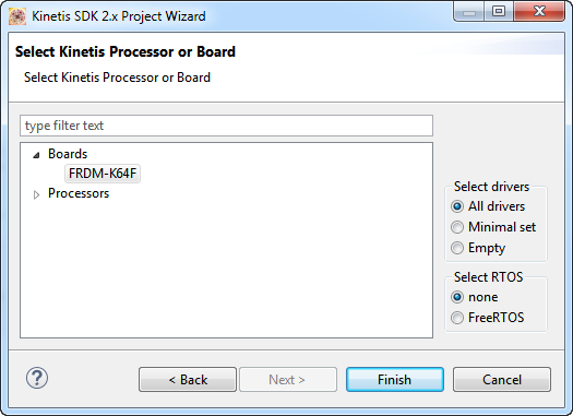
Next, select the board or processor. With selecting a board it will pre-configure things like UART. If you want to create a minimal project, select the device from the list of processors.
The selection of drivers and RTOS depends on the needs, in this example I use ‘all drivers’ and ‘no RTOS’:
Select Board
The pin muxing files are inside the ‘board’ folder:
pin muxing in board folder
I need to replace the pin_mux.c and pin_mux.h with the configuration files created by the Pins tool. For this, I have several options:
- copy-paste: I can select the content of the files (CTR-A to select all), then copy it (CTRL-C), and finally pasting it into the source editor view in Eclipse. Do this for the .c and .h file.
- export: Use the export menu.
To export in the web version, use the menu item in the Pins menu:
Export Pins Menu Item
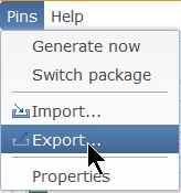
In the desktop version that function is under the File menu:
Export in Desktop Pins Tool
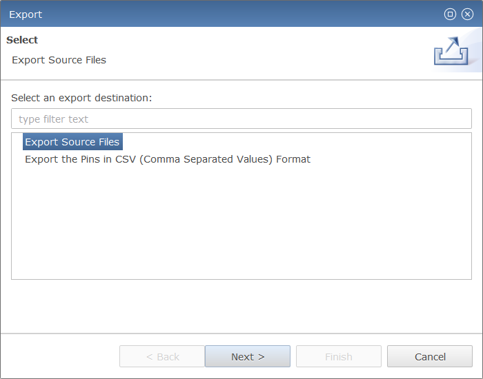
Select Export Source Files, press Next.
Exporting Source File
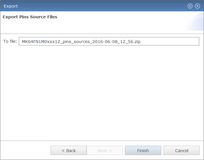
In the next dialog I can specify the file name:
zip file name
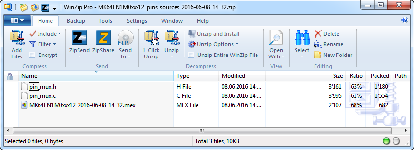
Press Finish, and it will download a zip archive:
Zip Archive
The archive includes both the pin_mux.h and pin_mux.c which I can use to replace the files inside my SDK V2.0 project. Additionally it includes the .mex file which I can import again into the tool.
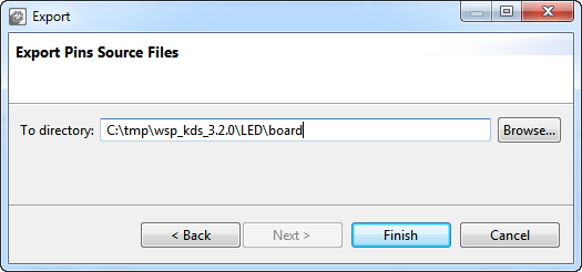
With the desktop version of the tool it is even simpler: I can directly specify where the files should be stored, e.g. inside my project:
Pins Desktop to store files in folder
If the file(s) already exist, I will be prompted to overwrite them.
Toggling the LEDs
The new pin_mux.c and pin_mux.h only do the muxing.The muxing code get called with BOARD_InitPins() from main():
int main(void) { &amp;amp;nbsp; /* Init board hardware. */ &amp;amp;nbsp; BOARD_InitPins(); &amp;amp;nbsp; BOARD_BootClockRUN(); &amp;amp;nbsp; BOARD_InitDebugConsole(); &amp;amp;nbsp; /* Add your code here */ &amp;amp;nbsp; for(;;) { /* Infinite loop to avoid leaving the main function */ &amp;amp;nbsp;&amp;amp;nbsp;&amp;amp;nbsp; __asm("NOP"); /* something to use as a breakpoint stop while looping */ &amp;amp;nbsp; } }They do not implement the GPIO driver initialization. So I need to add code to initialize the GPIO driver and configure the pins for output:
#define LED_RED_BIT&amp;amp;nbsp;&amp;amp;nbsp;&amp;amp;nbsp; 21 /* PTB21 */ #define LED_GREEN_BIT&amp;amp;nbsp; 22 /* PTB22 */ #define LED_BLUE_BIT&amp;amp;nbsp;&amp;amp;nbsp; 26 /* PTE26 */ static const gpio_pin_config_t LED_configOutput = { &amp;amp;nbsp;&amp;amp;nbsp;&amp;amp;nbsp; kGPIO_DigitalOutput,&amp;amp;nbsp; /* use as output pin */ &amp;amp;nbsp; 1,&amp;amp;nbsp; /* initial value */ }; /*! &amp;amp;nbsp;* @brief Initialize GPIO. &amp;amp;nbsp;*/ static void InitGPIO(void) { &amp;amp;nbsp; GPIO_PinInit(GPIOB, LED_RED_BIT, &amp;amp;amp;LED_configOutput); /* configure PORTB21 as output */ &amp;amp;nbsp; GPIO_PinInit(GPIOB, LED_GREEN_BIT, &amp;amp;amp;LED_configOutput); /* configure PORTB22 as output */ &amp;amp;nbsp; GPIO_PinInit(GPIOE, LED_BLUE_BIT, &amp;amp;amp;LED_configOutput); /* configure PORTE26 as output */ }Below is the complete code in main.c which calls the initialization and toggles the pins inside main():
#include "board.h" #include "pin_mux.h" #include "clock_config.h" #define LED_RED_BIT&amp;amp;nbsp;&amp;amp;nbsp;&amp;amp;nbsp; 21 /* PTB21 */ #define LED_GREEN_BIT&amp;amp;nbsp; 22 /* PTB22 */ #define LED_BLUE_BIT&amp;amp;nbsp;&amp;amp;nbsp; 26 /* PTE26 */ static const gpio_pin_config_t LED_configOutput = { &amp;amp;nbsp;&amp;amp;nbsp;&amp;amp;nbsp; kGPIO_DigitalOutput,&amp;amp;nbsp; /* use as output pin */ &amp;amp;nbsp; 1,&amp;amp;nbsp; /* initial value */ }; static void InitGPIO(void) { &amp;amp;nbsp; GPIO_PinInit(GPIOB, LED_RED_BIT, &amp;amp;amp;LED_configOutput); /* configure&amp;amp;nbsp; PORTB21 as output */ &amp;amp;nbsp; GPIO_PinInit(GPIOB, LED_GREEN_BIT, &amp;amp;amp;LED_configOutput); /* configure&amp;amp;nbsp; PORTB22 as output */ &amp;amp;nbsp; GPIO_PinInit(GPIOE, LED_BLUE_BIT, &amp;amp;amp;LED_configOutput); /* configure&amp;amp;nbsp; PORTE26 as output */ } /*! &amp;amp;nbsp;* @brief Application entry point. &amp;amp;nbsp;*/ int main(void) { &amp;amp;nbsp; /* Init board hardware. */ &amp;amp;nbsp; BOARD_InitPins(); &amp;amp;nbsp; BOARD_BootClockRUN(); &amp;amp;nbsp; BOARD_InitDebugConsole(); &amp;amp;nbsp; /* Add your code here */ &amp;amp;nbsp; InitGPIO(); &amp;amp;nbsp; for(;;) { /* Infinite loop to avoid leaving the main function */ &amp;amp;nbsp;&amp;amp;nbsp;&amp;amp;nbsp; GPIO_TogglePinsOutput(GPIOB, 1&amp;amp;lt;&amp;amp;lt;LED_RED_BIT); /* toggle RED LED */ &amp;amp;nbsp;&amp;amp;nbsp;&amp;amp;nbsp; GPIO_TogglePinsOutput(GPIOB, 1&amp;amp;lt;&amp;amp;lt;LED_GREEN_BIT); /* toggle GREEN LED */ &amp;amp;nbsp;&amp;amp;nbsp;&amp;amp;nbsp; GPIO_TogglePinsOutput(GPIOE, 1&amp;amp;lt;&amp;amp;lt;LED_BLUE_BIT); /* toggle BLUE LED */ &amp;amp;nbsp;&amp;amp;nbsp;&amp;amp;nbsp; __asm("NOP"); /* something to use as a breakpoint stop while looping */ &amp;amp;nbsp; } }With that, the project should compile and build just fine.
Running the program with the debugger, and it toggles the RGB LED on the board 🙂
Toggle LED
Summary
With the Pins tool I have now a way to configure and mux the pins with my SDK V2.0 projects. It is an easy to use tool, which just does that: dealing with the pins. For anyone who does not want to install the tool, there is a web-based version. Personally I prefer the tool installed as desktop version: that way I can store it in a version control system so I have it always available.
I love the way how the tool stores and uses its data directly in the sources using YAML. This makes it simple and easy to pass muxing information around, and the settings will be automatically stored in the version control system with the YAML settings in the sources.
I hope you find that tool as useful as I do.
Happy Muxing 🙂
Links
- FTF 2016 training and presentations: FTF-DES-N1958, FTF-DES-N1960 and FTF-DES-N1957
- Kinetis SDK web site: http://kex.nxp.com/
- Kinetis Design Studio web site: http://www.nxp.com/kds
- YAML format: https://en.wikipedia.org/wiki/YAML


Nice post.!
LikeLike
Oh( Looks like european developers tend to make cube-like codegenerators. As for me I find STM approach is not convenient: a lot of helper-tool that you need to configure and after import to project. In my view PEx approach was a way much better-if you want to change something the all you need is to go to the pin-mux tab and change it. And with that tool you need to re-import. Also PEx has processor-view in pinmux tab. What is the advantage of using that one tool?
LikeLiked by 1 person
Hi Alexey,
to me, each approach has its benefit. What I like with that Pin tool is that it just does one thing. Which makes it easier to use for someone who just wants to do that, but not configuring and working with all the rest of the system. For example when student teams are developing their hardware and software projects, the ‘hardware group’ could use the Pins tool to assing the pin functions for the layout, without the need to deal with a advanced and more powerful tool like Processor Expert which can do everything. About the re-import points: that’s why I prefer more the desktop tool: I could launch it from Eclipse, change the mux and then save the files directly back to the project folder/files. Not as convenient as using Processor Expert, but a workable solution. I see why the Pins tool is a separate executable to be IDE agnostic and to work with all the non-Eclipse IDE’s (are there still non-Eclipse IDE’s 😉 ), or if for whatever reason someone does not want to use an Eclipse IDE. But I wish there could be an Eclipse plugin for this Pins tool, that would make it much better intergrated and useful (at least for Eclipse users).
LikeLike
“1 click does it all” (c) Freescale 😉
LikeLike
I guess we are still missing the big picture as to where NXP are going with Kinetis development support, I still don’t feel confident to move on from PE and KSDK 1.3. Too much fluidity.
LikeLiked by 1 person
Hi Jim,
I think there is no reason to move away from a working solution and combination of tools. And I think too given the Freescale and NXP merger things fluid for now, and probably will stay fluid for a while. Based on the information given at FTF the Pins tool is just the first one (well, after the power estimation tool), and next will be the clock configuration tool. So from this perspective, the Pins tool is the first piece of a larger set of tools.
LikeLike
It is not good approach.
I have worked with Microchip, Atmel and NEC controllers and PE was the stronger reason to switch to freescale.
From by point of view, PE is by far better tool than the new graphical environment.
LikeLiked by 1 person
Hi Nikos,
for sure Processor Expert does currently much more than the Pins tool, and is much better integrated into the Eclipse IDE. On the other side I like the more modular approach, plus that now things work seamless with a version control system. Using Processor Expert in a team with version control is very difficult and frustrating.
Erich
LikeLike
Great article Erich – though I noticed a rather unfortunate typo in the 2nd diagram (application startup).
LikeLiked by 2 people
lol i noticed that too.
LikeLike
Yup, fixed 🙂
LikeLike
Yeah… You never know how your rooster will behave at reset…
LikeLike
Yes, as a firmware engineer you have to be prepared for *everything*, including roosters 🙂
LikeLiked by 1 person
Hi Dave,
what’s wrong with a rooster in an embedded application ;-).
Erich
LikeLike
Hi Erich.
It’s a good explanation.
Can explain it with an example about pwm and uart configuration?
Best regards.
LikeLike
Hi Juan,
it works the same for any pins, including PWM and UART.
Erich
LikeLike
DOC-331538 on community.nxp.com
LikeLike
Pingback: NXP Pins Tool: Clock Gates and Controlling the Bits | MCU on Eclipse
Pingback: NXP Pins Tool: Understanding Data for Offline Usage | MCU on Eclipse
Pingback: Tutorial: Getting ETM Instruction Trace with NXP Kinetis ARM Cortex-M4F | MCU on Eclipse
Pingback: NXP MCUXpresso Software and Tools with Clocks Tool | MCU on Eclipse
Pingback: MCUXpresso IDE: Installing Processor Expert into Eclipse Neon | MCU on Eclipse
Hi Erich
I am using MCUX 10.3 and I have a question about the pins tool. The MCUX Config Tools Users Guide says “Every routed pin appears in the Routed pins table”. However, with some projects I have imported from the SDK, there are routed pins in the Pins/Peripheral Signals table, that are not shown in the Routed Pins table underneath. Obviously I can put them there but I was wondering if there is a way to ensure that the two tables are in sync with each other. Or does it not matter?
I hope this is clear.
Thanks
Steve
LikeLike
Well, I think they should show up. Is there anything special with the pins not showing up?
And the tables are just informative, as long as the generated code does what it should do.
LikeLike
Hi Steve,
now I see what you mean. Here is the explanation: the ‘Routed Pins’ view on the bottom only shows the pins for a so called ‘functional group’, e.g. the pins to initialize the I2C or the UART. To switch between the functional groups, use the that ‘functional Group’ drop-down list in the top toolbar of the IDE (about in the middle). Or right-click on a pin in the ‘Pins’ view and select the ‘Select ….’ option.
I hope this makes it clear?
Erich
LikeLike
Pingback: Investigating ARM Cortex® M33 core with TrustZone® – Using the Pins Config Tool | MCU on Eclipse