The FRDM-K22F is one of the latest members of the Freedom board families: 512 KByte Flash, 128 KB RAM and the usual Freedom board components on it. Unfortunately, Freescale decided not to populate the micro-SD card connector on the board, so from this perspective the FRDM-K64F is more value for the money. But the board has USB, so this makes it still interesting. And this is what this post is about: Adding USB to the FRDM-K22F board in a few minutes…
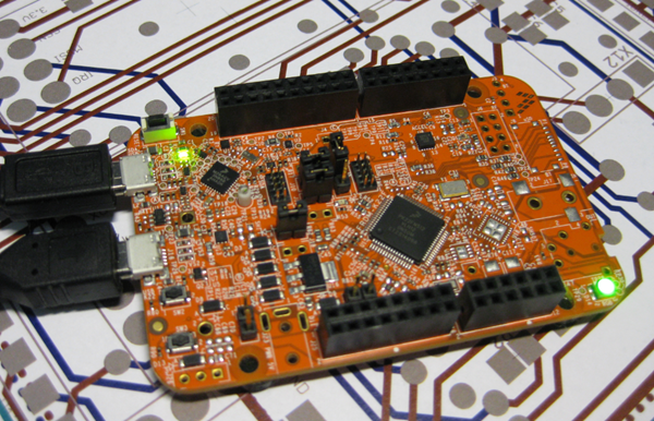
Freescale FRDM-K22F Board
Software Update
I’m using Kinetis Design Studio in this post with Processor Expert components.

Components
You need the “Processor Expert Support for Kinetis K22F/KV31F @120/100MHz Service Pack” installed. You get that update with the menu Help > Install New software and use the
http://nxp.com/lgfiles/updates/Eclipse/KDS
update site:

Installed K22F Service Pack
Additionally, you need the latest McuOnEclipse Processor Expert components from SourceForge (https://sourceforge.net/projects/mcuoneclipse/files/PEx%20Components/), see “McuOnEclipse Releases on SourceForge“.
Project Creation
Create a new project for Processor Expert in Eclipse and for the MK22FN512xxx12 device:

New Project for MK22FN512
Do *not* select the Kinetis SDK option, only select Processor Expert:
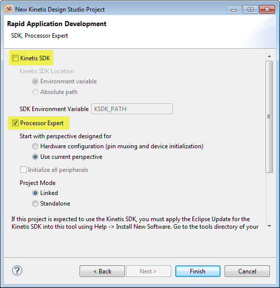
Processor Expert Project
Clock Configuration
The K22 can run up to 120 MHz. I configure it to maximum speed, similar to the K64F (see “FRDM-K64F at Maximum Speed of 120 MHz“). I have the 8 MHz external crystal enabled:

Enabled External 8 MHz Crystal
MCG is set to PEE with a PLL output clock of 120 MHz:
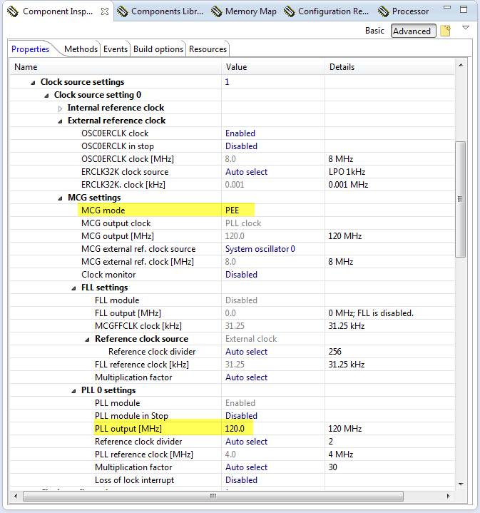
PEE with 120 MHz Clock
System clocks are set to the maximum possible values:

System Clocks
USB Configuration
Add the FSL_USB_Stack component to the project. I’m using here a USB CDC Device class. Configure it to use Init_USB_OTG_VAR0 and enable USB CDC Device class:

USB Component Configuration
Enable the clock gate and have it to use the PLL/FLL clock with the clock divider output as clock source. To build the needed 48 MHz USB sampling clock from the 120 MHz PLL clock, use a multiplier of 2 with a divider of 5:
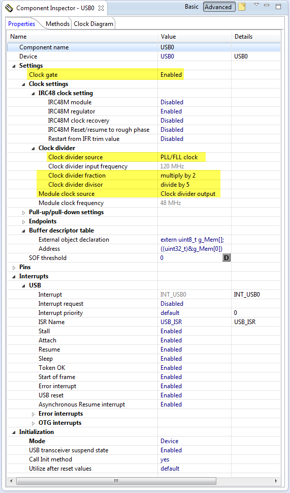
USB Init Configuration
Finally, select the K22FN120 as CPU in the USB CDC sub component:

USB CPU Selected
That’s it!
Application Code
What is missing is now the application code. It can be very simple as this:
#include <stdio.h> static uint8_t cdc_buffer[USB1_DATA_BUFF_SIZE]; static uint8_t in_buffer[USB1_DATA_BUFF_SIZE]; static void CDC_Run(void) { int i, cnt = 0; uint32_t val = 0; unsigned char buf[16]; for(;;) { while(CDC1_App_Task(cdc_buffer, sizeof(cdc_buffer))==ERR_BUSOFF) { /* device not enumerated */ LED1_Neg(); LED2_Off(); WAIT1_Waitms(10); } LED1_Off(); LED2_Neg(); if (CDC1_GetCharsInRxBuf()!=0) { i = 0; while( i<sizeof(in_buffer)-1 && CDC1_GetChar(&in_buffer[i])==ERR_OK ) { i++; } in_buffer[i] = '\0'; (void)CDC1_SendString((unsigned char*)"echo: "); (void)CDC1_SendString(in_buffer); UTIL1_strcpy(buf, sizeof(buf), (unsigned char*)"val: "); UTIL1_strcatNum32u(buf, sizeof(buf), val); UTIL1_strcat(buf, sizeof(buf), (unsigned char*)"\r\n"); (void)CDC1_SendString(buf); val++; } else { WAIT1_Waitms(10); cnt++; if ((cnt%1024)==0) { /* from time to time, write some text */ (void)CDC1_SendString((unsigned char*)"Type some text and it will echo.\r\n"); CDC1_SendBlock((unsigned char*)"hello?\r\n", sizeof("hello?\r\n")-1); } } } }Summary
The K22F is the latest addition to the list of supported USB microcontroller in the FSL_USB_Stack component. The example project featuring USB CDC is available on GitHub.
Happy USBing 🙂
Links:

Many thanks!!
I just ordered a K22 board so this will be the first project to do.
Thanks for the KDS update advice too.
Best regards!!!
LikeLike
Pingback: McuOnEclipse Components: 27-Dec-2014 Release | MCU on Eclipse
Hi!
Many thanks for your excellent tutorials.
When should we use the mcuoneclipse FSL_USB_Stack component and when should we use the fsl_usb_descriptors, fsl_usb_framework and fsl_usb_device_* components?
I’m trying to get a USB MSD device working on my custom K64-based board with an SD card for storage. It appears that the Freescale fsl_usb_device_msd_class component is the tool for the job. When I add it to my project, it brings with it a usb_descriptors component and a fsl_usb_framework component. I think everything is set up right (clocks, initialisation, etc), but when I plug in USB, nothing happens. The init code runs fine, and the code jumps correctly through all the error handling without printing (or trying to print) any errors out to the debug console (which is itself working fine). However, enumeration doesn’t seem to get anywhere at all. Perhaps I need to set up and handle some callbacks, or something?
Before I get into a thorough debugging session, it would be good to have an overview of what components I’m actually supposed to use!
It seems that the KDS 2.0.0 + KSDK 1.1.0 + Processor Expert combination is in a lot of flux at the moment, and almost completely undocumented! Am I right, or am I missing something? The built in “Help on Component” feature in KDS is woefully inadequate! There don’t seem to even be any KDS+Processor Expert examples formally supplied by Freescale.
Since I’m new to the Kinetis tools, I would prefer to start with KDS rather than the deprecated CW stuff.
Cheers
Jeff
LikeLike
Hi Jeff,
thanks 🙂
the fsl_ (lower case) components are only working with the Kinetis SDK (http://www.freescale.com/ksdk) projects. I have not used them for my USB projects yet (I always used the FSL_USB_Stack components so far. For the reasons you mention in your comments. If enumeration does not work: check if USB interrupts are enabled and working (set a breakpoint in the interrupt service routine). And yes: use KDS, CW is depreciated.
I hope this helps.
Erich
LikeLike
Thanks for the quick reply, Erich! I will revisit this once I’ve got some of my basic parts to work. I’m using KSDK so I’ll try the lowercase variants.
Currently crawling through fire to get the comparator output pin out of tristate so I can begin to find out why my comparator doesn’t work! Glacial progress with this toolchain. 3 days in and I’ve only got UART and an LED!
Keep up the great work!
LikeLike
Hi Erich,
I’m still stuck on this I’m afraid! The usb demo code works ok (dev_msd_disk_frdmk64f_bm_frdmk64f) but I want to build a standalone version that is not reliant on the precompiled libusbd_bm.a and libksdk_platform.a . I need a clean code tree that is all in one git repository.
I’ve tried with the fsl_usb_ components, as well as by copying the KSDK-1.1.0/usb folder into my source tree and building it that way. Both produce the same outcome – the USB-MSD stack initialises ok (lots of USB_OK’s, and correct debug print statements) but when you plug in a USB cable it doesn’t enumerate. No interrupts fire.
A little more background info here:
freescale community thread/353811
Do you have any ideas? The freescale forum is very quiet!
Many thanks
Jeff
LikeLike
Hi Jeff,
I’m affraid that I cannot help you much here. So you are saying that it works with the library, but not if you build the files yourself? That sounds like the library is build with different set of options or settings?
Erich
LikeLike
Pingback: Proof of Concept: Open Source ARM SWD Debug and General Purpose Board | MCU on Eclipse
Hi Erich,
I have implemented this project and have seen that USB CDC implemented in this project is bus-powered but I couldn’t find any option to toggle between self-powered and bus-powered options inside FSL_USB_STACK component.
Thanks,
Saad
LikeLike
I believe there is no option for that.
LikeLike
Hi Erich,
Powering mechanism is catered inside configuration descriptors in USB 2.0 standard. In FSL USB Stack, this is implemented in g_config_descriptor() function inside usb_descriptor.c and is enabled for all three powering options (Bus-powered, Self-powered and Remote wake-up). There is no option available in processor expert to change it to any specific powering option.
LikeLike
Hi Muhammad,
ok, I can easily add a setting for this.
Erich
LikeLike
Hi Muhammad,
I have implemented an additional setting in the component, so you can enable/disable bus powered and self powered options.
I’m going to commit the changes on GitHub, are you able to get it from there?
I plan to release new *.PEupd files soon, but I don’t know when I can do this.
Thanks,
Erich
LikeLike
Hi Please help me.
I am trying the same on K22F board.
1. Using KSDK1.2 latest version.
2. KDS latest version 3.0
3. Freescale K22F
I follow all the steps as explained by you. But I get error. USB0: “Device not supported on selected processor”
Please help me. I am stuck with this problem from many days.
LikeLike
Hi Vishal,
have you cerated that project with the Kinetis SDK option enabled? With the Kinetis SDK, many Processor Expert components do *not* work, including my FSL_USB_CDC one. So if you create your own new project, make sure you select ‘none’ for Kinetis SDK.
I hope this helps,
Erich
LikeLike
Pingback: tinyK20: New Board with micro-SD Card | MCU on Eclipse
Hello Erich!
Thanks for the nice post!
I imported your project, and tried to run in my K22F board.
I use the USB_CDC_SEGGER Debug.
The code is stucked in this loop:
while(CDC1_App_Task(cdc_buffer, sizeof(cdc_buffer))==ERR_BUSOFF)
How can I run the code correctly?
Can I open the com port with Putty and see the USB activity?
Where did you configure the baud rate?
I’m a little confused. hehe
Thanks in advance.
LikeLike
Hi Guiherme,
if you are stuck in this while loop, it means that the board was not able to enumerate (connect) with the host PC. Have you used as second USB cable to connect to the K22F port (USB)?
And yes, you can use Putty or any other terminal program to connect to the board: open the COM port which has been installed/enumerated with that board.
Baud: that’s a thing of UART, not of USB. USB CDC does not have a baud rate. So you can use any baud you like in the terminal (I prefer 38400).
I hope this helps.
LikeLike
Yeah, I tried to connect with 2 cables, but I saw now… my driver is with some warning problem in windows device manager.
I found another post in your site that you explain how to set the things on… hehehe
Erich, I really aprecciate your help.
In 10 lines you explained all my doubts about the usb connection problem.
Thanks, my friend, and congratulations by your excelent work in the site!
LikeLike
Pingback: Microchip DAC Module MCP49xx on FRDM-K22F using Software SPI | TechnoChronicle
Hello.
Is there any problem to use the FRDM-K22F running in 120 MHz, using SPI and USB at the same project? Because the SPI is not working, only the USB.
LikeLike
Hi Kauã, I’m not aware of such a project. Any idea what is not working?
LikeLike
Hi Erich, basically the SPI clock is not toggling when the processor MK22FN512VLH12 is operating in 120Mhz, but when we put the standard frequency of the processor it works.
LikeLike
Interesting. I have not used SPI yet on the K22F. Which SPI/pins are you using?
LikeLike
I’m using the pins PTD4 (CS), PTD5 (SCLK), PTD6 (DIN), PTD7 (DOUT).
LikeLike
Hi,
I am not using the combination of SPI and USB. I am only using SPI in my project. And for me, it works at 120 MHz. I am using following pins.
PTC9 –SDCARD_DETECT
PTD0 — SPI0_PCS0 SDCARD_CS
PTD1 — SPI0_SCK SDCARD_SCK
PTD2 — SPI0_MOSI SDCARD_MOSI
PTD3 — SPI0_MISO SDCARD_MISO
LikeLike
Hi Vishal,
are you using the SD card footprint/socket on the FRDM-K22F for this? I have put a socket on it (same as on the FRDM-K64F board), but somehow I do not get it to work :-(. I have a core clock of 120 MHz, maybe I see that problem with USB too?
LikeLike
Hi Vishal,
It works now :-). I have sorted out my problem: I was sending LSB instead of MSB on the SPI bus 😦 So I have now both the SD card and USB working on the FRDM-K22F with 120 MHz core clock. Project is my ‘Kinetis Drone’ project on GitHub:
LikeLike
I can confirm that my SPI clock works (on PTD1) with 120 MHz and USB enabled.
LikeLike
Hi Erich,
I was not using the SD card footprint socket. I was using the pin headers. Great to hear that it works. 🙂
LikeLike
Yes, it works great. I think I will post a short article about how to add a SD connector to the FRDM-K22F board.
LikeLike
Hi, Erich
I want to use “K20DX256VLK10” in my project, and CDC, but I found the component FSL_USB_Stack doesn’t support this MCU, please let me know, how can I use CDC in this projetc? or, do you mind add this MCU to component, thank you very much
LikeLike
Hi henry,
I think the K20DX256 is compatible with the K20DX128 (on the FRDM-K20D50M board). I use the ‘Kinetis K20D50’ setting for that device and it works fine. I suggest you do the same for the K20DX256.
LikeLike
thanks a lot, Let me try!
LikeLike
Hi, Erich,
I have test with K20d50, it doesn’t work, I think becase k20DX128 is running 50 Mhz, but K20DX256xxx10 is running at 100Mhz, even I set up to 96Mhz for it, please let me know, what can I to try?
thanks a lot
LikeLike
Hi Henry,
you need to make sure that your USB clock gates are enabled and that the USB block is feed with a 48 MHz clock from the PLL.
Other than that: see the comments in https://mcuoneclipse.com/2013/04/27/usb-cdc-with-the-frdm-k20d50m/ so you might use a K20D72 or K20F120
Erich
LikeLike
thanks Erich, I try to use K40 in my projrect, and I sucess
LikeLike
Hi Erich,
I have run into a strange problem in USB CDC using your component; since I updated KSDK 1.3.0 (which I am definitely not using in CDC project), I can not select USB Init as Init_USB_OTG_VAR0 in processor expert. This option is not available at all. Although I am not using OTG but this error doesn’t allow processor expert to generate the code. Can you please tell if there is any link between the KSDK and CDC component?
Regards,
Saad
LikeLike
Yes, I have seen such a problem in several of my projects, but did not think that it could have been caused by the SDK v1.3 update :-(. So thanks for that tip.
Are you using my latest version of the components from SourceForge? Because in the most recent version I have added the ability that you can add the Init_USB_OTG_VAR0 *outside* the USB component. Set the ‘Inherited USB Init’ to disabled and have the Init component added outside of the USB component.
I hope this helps.
LikeLike
No, I am using “Component_2015_03_22” which are quite old but I have built a big project with several other components as well so I assume I can not replace the FSL_USB_STACK component in the project with a new revision.
If I update components in eclipse then will it update the FSL_USB_STACK already being used in the project or I’ll have to add the new component to project again?
LikeLike
It is always good to make a backup (just in case). The components are stored here: C:\ProgramData\Processor Expert
If you update the components, it will overwrite the existing version. You don’t have to add new components to the project again. But you might need to add a few additional components (e.g. utility, or Kinetis SDK, or CriticalSection) as some of them have been referenced in addition. Should not be a big deal.
LikeLike
I have updated the 22.11.2015 components into PEx. I wanted to know that can I use KSDK 1.3.0 components and PEx components within the same project?
Regards,
Saad
LikeLike
Hi Saad,
you can use the Freescale provided PEx components which names are starting with “fsl_”. You cannot use any components which end with “_LDD” and no other components provided by Freescale (ahem: NXP) which are using hardware. You can use many of the McuOnEclipse components especially the ones which do not depend on hardware. You can use the McuOnEclipse FreeRTOS component, but you cannot use the “FSL_USB_Stack” component as it depends on the USB hardware. In general: the Kinetis SDK is very different and you cannot use it with components created before the SDK area.
I hope this helps?
LikeLike
Hi, Erich,
Do you have any idea for how to use hardware floating point with K22F?
Thanks a lot
LikeLike
It accelerates the single precision floating point operations, saving you a lot of processing time. Using software floating point would need more stack and processing time than using the hardware.
LikeLike
if I use it same as software floating point?
float a,b;
o
LikeLike
Yes, usage in the sources is the same regardless if you are using hardware or software floating point.
LikeLike
Pingback: USB CDC with the Raspberry Pi | MCU on Eclipse
Hi Erich,
Is there a way to set the required USB current in the configuration descriptor? Currently, I have to manually modify the usb_descriptor.c file to set maximum power to 500mA because my CDC device requires about 300mA to work.
Are you planning to add the power setting feature in the next release of the PE components.
Many thanks,
Kevin Le
LikeLike
Hi Kevin,
I had not planned for that, but I think I easily could do that. I’ll post a comment once I have implemented it, OK?
LikeLike
I have implemented it now, so you can specify the current consumption: https://github.com/ErichStyger/McuOnEclipse_PEx/commit/1c4b215e1218b2eeeda42f2b71692526256b5512
LikeLike
Hi, I’m trying to get a USB CDC implementation working on a custom board using a 120 MHz K22FN processor, almost the same as on the Freedom board. Following the steps in this post, I was able to get the board enumerating as a USB device, but I would really like to be able to use the FSL_USB_STACK component in a KSDK 1.3 project. The KSDK fsl_dpsi peripheral is pretty essential for what I’m trying to do – reconfigure programatically from an SPI slave to SPI master, which the MCU on Eclipse SPI LDD components cannot do.
Anyways, using a KSDK 1.3 project, I can add and configure the FSL_USB_STACK component, but the INIT_USB_OTG inherited component always throws errors, saying that “the component is incompatible with the selected processor”, and will not let me enable the clock gate or change other config parameters.
I tried adding a non-inherited INIT_USB_OTG component with the same configuration as the one generated by FSL_USB_STACK, but using the non-inherited component, I cannot get the device to enumerate. It fails saying it cannot get descriptor info.
Any ideas?
LikeLike
Hi Devin,
yes, the problem is the INIT_USB_OTG component. In my latest component version, you could can disable the ‘Inherited USB Init’. But then do not add the INIT_USB_OTG component. Instead, you need to add code to your application which does the same (initializing the USB). I have not tried that, but if done properly, it should work.
If it does not enumerate, it might be a problem with your clocking (make sure the USB is clocked with 48 MHz) plus that the interrupt vectors are configured properly.
I hope this helps,
Erich
LikeLike
Hi Devin,
I have updated the component (pushed to GitHub) to make it easier to be used with the SDK: https://github.com/ErichStyger/McuOnEclipse_PEx/commit/134cb2b11316e9bffffb7abf1f82141145c19c95
LikeLike
Hi Erich,
I tried using the enumerating, non-SDK project to generate code to the SDK, non-enumerating project, but even after resolving all of the dependencies calling USB0_Init just results in getting stuck inside DefaultISR.
My clock config is fine, using a crystal-less, 120/60/48 MHz config for Core/Bus/USB respectively.
Any advice on how to get USB initialized without using either the inherited or SDK verion of the USB_Init_OTG module? It would be awesome to get this working, as I personally find the SDK USB implementation (fsl_usb_framework) baffling, and would rather steer clear of it.
LikeLike
Hi Devin,
I made some progress today on the same thing with a FRDM-K64F. I have it not fully working yet, but close I think. I hope I can put it up (working) on GitHub soon. If you end up the DefaultISR than this tells me that probaly the USB interrupt vector is not pointing to the USB interrupt service routine which is USB_ISR(). I added something like this as a quick wrapper:
void USB0_IRQHandler(void) {
USB_ISR(); /* call USB handler */
}
The other thing is I had to add the clock ungating to the USB0_Init() I have copied from the Processor Expert version (non-SDK):
static void USB0_CommonInit(void) {
/* SIM_SCGC4: USBOTG=1 */
SIM_SCGC4 |= SIM_SCGC4_USBOTG_MASK;
/* SIM_SOPT2: USBSRC=1 */
SIM_SOPT2 |= SIM_SOPT2_USBSRC_MASK;
/* NVICIP53: PRI53=0 */
// NVICIP53 = NVIC_IP_PRI53(0x00);
NVIC_SetPriority(USB0_IRQn, 0);
}
void USB0_Init(void) {
USB0_CommonInit();
/* Register ‘USB0_CTL’ initialization */
….
}
I hope this helps,
Erich
LikeLike
Just saw the changes to FSL_USB_Stack.drv, what were you trying to do on line 273? USB0_IRQn just shows up as undefined. Is the ISR name meant to be a placeholder?
LikeLike
Nevermind, I got it. It’s defined by one of the SDK includes. I’ll try implementing your changes to the USB init and IRQ, let me know if you get it working on your freedom board.
LikeLike
Pingback: First steps: ARM Cortex-M7 and FreeRTOS on NXP TWR-KV58F220M | MCU on Eclipse
Hi! I am following this USB Stack example, however I need to access the USB port as: MSD_Host.
I have the latest version of Kinetis and MCUOnEclipse. I re-created this example project above in Processor Expert and I have no application code yet. When the USB Stack is initializing, it enables the Interrupts and the CPU is always re-entering the “void USB_ISR(void)” in khci_kinetis.c. This behavior let me think the USB ISR Flag stay always raised and never get cleared. The CPU is then always looping within the “void USB_ISR(void)” function and the normal code never has a chance to be executed.
If I configure the USB Stack Device Class as “CDC Device” (Like in this example) I don’t have any Interrupt issue. If I configure it to “CDC Host” or “MSD Host” I have this interrupt problem.
LikeLike
Hi Francois,
you need the application part of the MSD Host, so it clears and handles the interrupts.
I have not tried it with the K22F, but you could look at the following articles:
https://mcuoneclipse.com/2013/03/02/usb-msd-host-for-the-freedom-board/ and https://mcuoneclipse.com/2013/07/10/usb-msd-host-for-the-frdm-k20d50m-board/
LikeLike
Hi, I am currently using an older processor: MK20DX256VLH7. Everything is working (including the USB) and we are in production with this processor right now. The problem is that my application need more RAM than expected and I am trying to port it to: MK22FN512VLH12. Both chips have the same pins configuration (this avoid PCB Layout changes) and this new chip has 128K RAM instead of only 64K.
While porting my project (that include the application part of the MSD Host) to this new processor I found this USB Interrupt problem. My original project has been written with an older version of Kinetis and Processor Expert but I am now using the latest versions when working on the MK22FN512VLH12.
While executing the “int main(void)” function It correctly enter into the “PE_low_level_init();” function. However it never returns from this function because when the USB interrupt is enabled, 100% of the CPU is dedicated to the “void USB_ISR(void)”. So even if I put the application part of the MSD Host, it will never be executed anyways. In the “FSL_USB_MSD_HOST” component, CPU setting is set to : “Kenitis K22FN120” as mentioned in this example.
I am an experienced embedded developer and I am suspecting there might be a bug in processor expert with the FSL_USB_MSD component on the MK22FN512xxx12 processor. Would it be possible to test this scenario on your side to see if you have the same issue?
LikeLike
Hi Francois,
I only have the FRDM-K22F board which is a MK22FN512. I have a project on GitHub here: https://github.com/ErichStyger/mcuoneclipse/tree/master/Examples/KDS/FRDM-K22F/FRDM-K22F_USB_MSD_Host
I quickly checked that project, and it seems to work properly (at least just running it on the board, I have not added a memory stick because had no time).
Can you check that project (for KDS V3.x)? The USB interrupts are Disabled in the Init_USB_OTG component, maybe this is your problem?
Maybe this helps?
Erich
LikeLike
Hi! The Interrupts were disabled in my project but I saw that the were getting enabled by the initialization code, even if the option was set to disabled. I checked your project and I saw that all the interrupts were also masked.. The interrupts were unchecked in PE (Stall, Attach, Resume,…) By doing the same thing in my project, it fixed my problem. Thanks!
LikeLike
Hi Francois,
many thanks for sharing the resolution!
Erich
LikeLike
Hi Erich,
I’m trying to get the USB stack working on a K22 board at work.
The problem i’m having with Kinetis Design Studio is that when I come to select the CPU in the “FSL_USB_CDC_Device”, the Kinetis device I’m using doesn’t appear in the list – even having applied the software update you suggested at the start of the tutorial yet the K22 doesn’t appear: K40, K60 and KL25 are my only options.
Have I missed a step?
Kind regards,
Kevin
LikeLike
Are you using the latest version of the components from SourceForge already(https://mcuoneclipse.com/2014/10/21/mcuoneclipse-releases-on-sourceforge/)?
LikeLike
Hi Erich,
Yes, I downloaded the latest version of the components and installed both parts of the update.
Kind regards,
Kevin
LikeLike
The option for the K22F is in the USB CDC subcomponent. Have a look at this project on GitHub: https://github.com/ErichStyger/mcuoneclipse/tree/master/Examples/KDS/FRDM-K22F/FRDM-K22F_USB_CDC
LikeLike
Hi Erich,
Have you ever attempted to create a dual CDC device running on a K22?
Kind regards,
Kevin
LikeLike
Hi Kevin,
I only used single USB CDC so far.
Erich
LikeLike
Hi Erich,
Your the most help that can be found on Kinetis …. Thanks again.
Question for today:
On my K22FN512 custom hardware I am dumping a ‘virtual debug screen’ through the USB CDC component.
In my program I keep a memory mapped virtual screen (about 120×40 chars) that I have routines that do formatted prints to an row,col address. There is also a second frame buffer that just contains the color attribute data and keeps a ‘dirty’ bit so I can tell if that location needs redrawing.
About 10 times a second I refresh the screen by building a output stream full of ANSI esc sequences for positioning the cursor and setting the color attribute, and the ascii chars.
I then send this stream out using ‘CDC1_SendString(Buffer);’, and buffer could be hundreds or in the case of an entire screen refresh, 5000 or more characters.
The terminal emulator program I am using is TeraTerm, and it usually nicely displays my screens, although there is a flakeyness when I am changing lots of info and if it loses some or all of an ANSI esc sequence my screen gets hashed.
I am trying to figure out how to make it more solid – I have upped the endpoint sizes, and the RX and TX buffer sizes (2048 is the max I can get away with, if I try 4096 something breaks in the compile) , which seems like it helped a some, but I am wondering if there is something I can do to make the screens perfect.
Clearly, possibly some (or all?) of the problem is that Tera Term is choking on the volume of characters (actually it might be the ansi esc sequences that give it more grief)
Any thoughts?
LikeLike
Hi Brynn,
about “if I try 4096 something breaks in the compile)”, I assume this is the linker complaining that you don’t have enough RAM?
LikeLike
it was an odd error, and it was the RTT system view module that didn’t compile. It didn’t say anything about ram or stack, but I assumed that was the problem. when I went back to 2048 for the RX and TX components, the error went away.
LikeLike
Hi Brynn,
i quickly tried RTT and USB CDC with ring buffers of 4096 bytes, and have not seen any problem. If you see it again, please let me know.
LikeLike
I assume it works fine if you say send the data with 1 Hz? Then there should be nothing wrong with the escape sequences.
Make sure your processor is running at max speed of 120 MHz.
Make sure the USB interrupt has the highest interrupt level (0) in the system: that way USB transfers are not interrupted.
Making the ring buffer largers helps that you can store more data in it until it needs to be sent. Have a look at CDC1_SendChar().
When the buffer is full it calls CDC1_App_Task() which then will prepare the packet so it can be picked up by the polling host. This will only send 64 bytes (unless you increase that buffer).
You should call CDC1_App_Task() frequently outside calling CDC1_SendStringBuffe(), I hope you are doing this? This will ensure that the Tx and Rx buffers are frequently processed.
Last but not least: remember that the host is driving the USB CDC transfer: so if the host (PC) does not poll the USB bus frequently enough you will see problems too. So this all might depend on the libraries of your host too.
LikeLike
I tried at 2 hz instead of the 20hz that the update runs at, and while it was better it still had issues.
My CPU was running at 96Mhz off my 16 Mhz external crystal, I figured out how to change it to 120Mhz and still have the USB at 48Mhz. That is going to help in general with it just being faster.
USB interrupt priority seems to be at the default priority of ‘0’
When I was checking that CDC1_app_task gets called alot (it is in a task that has a 10ms task delay at the end of the loop), I noticed that it is called with yet another buffer – cdc_buffer.
Tracking the size of this, it was only set to 1024, and had the comment
/*
DATA_BUFF_SIZE should be greater than or equal to the endpoint buffer size,
otherwise there will be data loss. For MC9S08JS16, maximum DATA_BUFF_SIZE
supported is 16 Bytes
*/
So, my endpoint was bigger than this. I cranked this size up ( it is in the USB1_FSL_USB_Stack component).
Now I have that one set to 4096, the out_endpoint set to 4096, and the TX ring buffer set to 4096.
(the in_endpoint is 512, and RX ring buffer is set to 512)
It now works almost perfectly. The only time it fails is sometimes when the ‘refreshEntireScreen’ is called either periodically or with a manual command, often it mangles.
As this routine was only created to try to redraw a mangled screen, I shouldn’t have to call it anymore.
And actually, it’s likely that when I call that routine – which sets the dirty bit on every character in the frame buffer -it builds a character stream that is bigger than 4096.
even with a screen of 100×40 it has to add the escape sequences everytime the color changes.
A simple fix to the full screen refresh is to just split it into two half screen refreshes which should never be more than 3k chars (unless I did something dumb like change the color of every character)
Thanks a bunch Erich!
Brynn
p.s. working on my next question already, but will try to stick it in the comment of the most appropriate thread…
LikeLike
Hi Brynn,
There are different buffers for CDC1_app_task(), as the USB stack uses pointers to it and it is necessary to separate the data if multiple data transactions are started. Unfortunately this is the way how they have architected the USB stack. Another thought: make sure you are using only a single task sending data to the USB CDC: if you have multiple tasks using the USB, you need a mutex in place to guarantee reentrancy as the USB stack is using global variables.
LikeLike
Hi Erich,
It’s working perfectly now. Getting the buffer sizes happy, and then in my screenupdate routine that builds the stream of characters and ansi escape sequences, it checks to see that it is not overrunning the buffer by just finishing up the current line if it is getting near buffer full. Since it only streams out frame buffer locations that have the dirty bit set, this works perfect – it will just take two or more calls in the rare case where I set the dirty bit on every character in order to force a complete update. which at 20Hz you can’t hardly notice.
Code was already only calling the CDC1_sendString in one task. However, CDC1_appTask does get called in several tasks, is that okay? ( I assume it must be, because of my perfect screen…)
Thanks Erich!
Brynn
LikeLike
Because CDC1_AppTask() is using its own buffer from outside, I think it *could* be ok to have it called just from one task. I have not checked if it really would be possible (the USB stack is not that easy to understand), but in my applications I have it called from one task only. If it works for you, great!
LikeLike
Hi Erich,
First, I would like to thank you for all the help you have provided for me and for my colleagues through your blog and through your components.
I am running into some unexpected behaviour using the example code for this component: FRDM-K22F_USB_CDC. I have changed the code which sends data to the CDC to only the following:
if (CDC1_GetCharsInRxBuf()!=0) {
… // not relevant
} else {
CDC1_SendBlock((unsigned char*)test_buf, 64);
}
I have earlier initialised the buffer (once only), e.g.:
char test_buf[65];
for (int i = 0; i < 64; i++) { test_buf[i] = '0' + (i % 10); }
test_buf[64] = 0;
On sending the data to a consumer application on the PC, the consumer registers a throughput of about 3072 bytes per second, or about 24000 baud.
I have also tested the performance with a FreeCntr at the source and sent the output to Putty running at a variety of baud rates. The result is the same: 3072 bytes per second.
Does this level of performance surprise you? This compares with a throughput of about 480000 baud using the OpenSDA UART to send the same data to the same consumer. I was hoping for something up to 3 MBaud, rather than 24 kBaud.
Thanks in advance for your thoughts on this,
Bruce
LikeLike
Hi Bruce,
thank you 🙂
To increase performance: check your USB_CDC_Device component settings: Under Configuration, there is a setting for DATA_BUFF_SIZE (in the latest released component). By default this is set to 64 bytes. For a high performance USB application I have set this to 1024 bytes. This should help you getting a higher data rate.
I hope this helps,
Erich
LikeLike
Hi Erich,
Thank you so much for your instant help!
I have made the following changes, with no discernible impact on performance:
USB1:FSL_USB_Stack – No changes
USB0:Init_USB_OTG – No changes
CDC1:FSL_USB_CDC_Device –
DATA_BUFF_SIZE=1024,
USB_EP0_SIZE=1024,
USB_EP1_SIZE=1024,
USB_EP2_SIZE=1024
Tx1:RingBuffer – Buffer Elements=1024
Rx1:RingBuffer – Buffer Elements=1024
After saving changes, USB1_DATA_BUFF_SIZE is now defined as 1024.
The throughput is still around 24 kBaud. Am I missing a setting?
Thanks again,
Bruce
LikeLike
Hi Bruce,
I don’t have my board with me, so cannot verify the performance.
My settings:
CDC1:FSL_USB_CDC_Device –
DATA_BUFF_SIZE=1024,
USB_EP0_SIZE=1024,
USB_EP1_SIZE=1024,
USB_EP2_SIZE=1024
Tx1:RingBuffer – Buffer Elements=1024
Rx1:RingBuffer – Buffer Elements=64 (I’m mostly sending)
SendDataBlock
Use Timout: enabled
App Task Timeout: 100 ms
Waiting time: 50 ms
LikeLike
Hi Erich,
Thanks once again.
Unfortunately there is no change in the performance using these settings.
Best regards,
Bruce
LikeLike
Hi Bruce,
hmm, not sure what else I can suggest here now 😦
LikeLike
Hi Erich,
I’m going to try to use the KSDK USB CDC code provided with MCUXpresso (dev_cdc_vcom_bm), which we have clocked at 6 MBaud and above.
Thank you for all your help. If at any time you – or any of your readers – find yourself speed-testing the PEx USB CDC components, I would be most interested in hearing the results.
Thanks again.
Bruce
LikeLike
Pingback: FatFS, MinIni, Shell and FreeRTOS for the NXP K22FN512 | MCU on Eclipse
Pingback: How to get Data off an Embedded System: FatFS with USB MSD Host and FreeRTOS Direct Task Notification | MCU on Eclipse
Pingback: Visual Studio Code for C/C++ with ARM Cortex-M: Part 1 | MCU on Eclipse