
For a university research project I need a fast microcontroller with lots of RAM and FLASH memory. I have ordered a TWR-KV58F220M board from NXP which arrived yesterday. The special thing is that it has on of these new ARM Cortex-M7F on it:
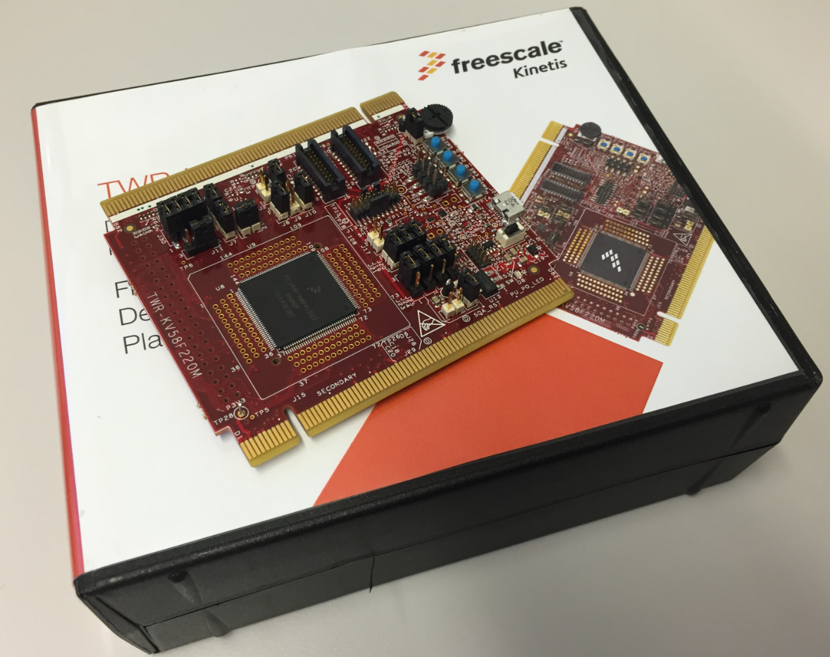
TWR-KV58F220M Box
The Tower board box comes with USB cables and a quick start guide, so everything to start with. The features of the KV58F1M0VLQ22 on the board are rather impressive:

PKV58F1M0VLQ22
- ARM Cortex-M7F running up to 240 MHz
- Single Precision Hardware Floating Point Unit (FPU)
- 1 MByte of FLASH
- 128 KByte of SRAM (there is another version of the device with 256 kByte)
💡 The marking on the device is KV58f1M0VLQ22, indicating 220MHz. Documentation and software are using 24 (for 240 MHz), and the tower board is labeled KV58F220M. So I’m not sure if there are two versions, one for 220 MHz and one for 240 MHz?
The microcontroller seems to be ideal for motor control, but the performance and features makes it attractive for other high performance applications. Compared to the very affordable price of NXP FRDM boards, the price of this Tower board is very high: US$ 159.00.
The board has 4 user buttons, 4 single-color LEDs, a potentiometer plus magnetometer/accelerometer on it. And it has an on-board debugger (OpenSDA V2.1).
Debugging
The board has an OpenSDA debug circuit (V2.1) on it, similar to the FRDM-K22F, so I can use either P&E or Segger debug firmware on it (I did not use OpenSDA). So I don’t need an external debugging probe.
But if I like, I can use an external debug probe like the Segger J-Link or the P&E Multilink.
P&E supports the M7 in KDS V3.2.0:
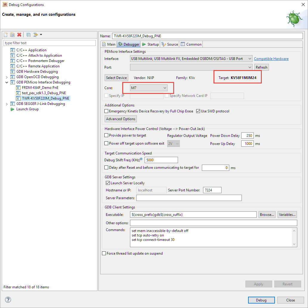
P&E and Cortex-M7
If I want to debug the board with an external P&E Multilink or Segger J-Link, I have to *remove* the jumpers J19 and J20:
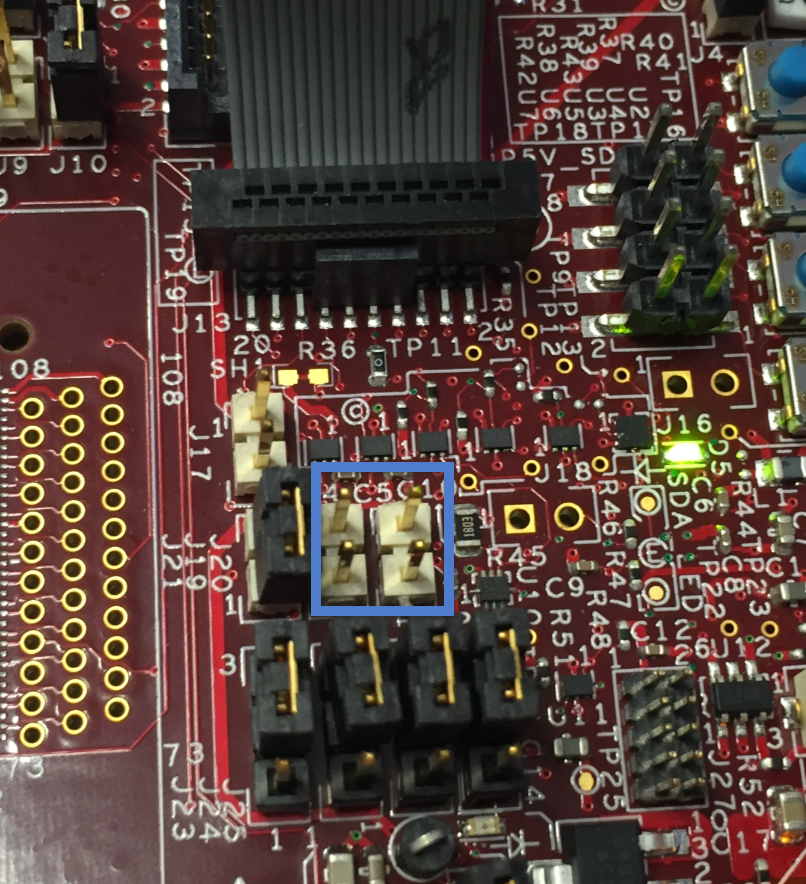
Jumpers J19 and J20 on TWR-KV58F220M
With this, debugging works fine with the P&E Multilink Universal:
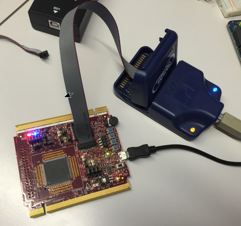
Debugging TWR-KV58F220M with P&E Multilink Universal
The same: it works fine with the Segger J-Link:

Debugging M7 with Segger J-Link
So with this, beside of the onboard OpenSDA circuit I can use an external debugging probe with the board.
FreeRTOS on M7
The target application will run with FreeRTOS, so the first thing I did was running a blinky with FreeRTOS on that board. And because this was the first time using it with an ARM Cortex-M7F CPU, I expected some tweaks and changes, but they were surprisingly minor.
There is a choice in the McuOnEclipse Processor Expert component to support Cortex-M7/M7F:

ARM Cortex M7 Selection in FreeRTOS
With this, the FreeRTOS port knows that it has to run on an ARM Cortex-M7 or M7F. I had to tweak a few things in the RTOS port, basically using most of the M4 code for the M7(F) port. So this was surprisingly simple.
In FreeRTOSConfig.h there is a configuration line item which identifies the core:
#define configCPU_FAMILY configCPU_FAMILY_ARM_M7F
Kinetis Design Studio and Kinetis SDK
I’m using the NXP Kinetis Design Studio V3.2.0 with this board. Because the KV58 is a new device, support for the KV58 needs to be added to the IDE. The usual way is to build the SDK for it on http://kex.nxp.com/ (see “First NXP Kinetis SDK Release: SDK V2.0 with Online On-Demand Package Builder“):
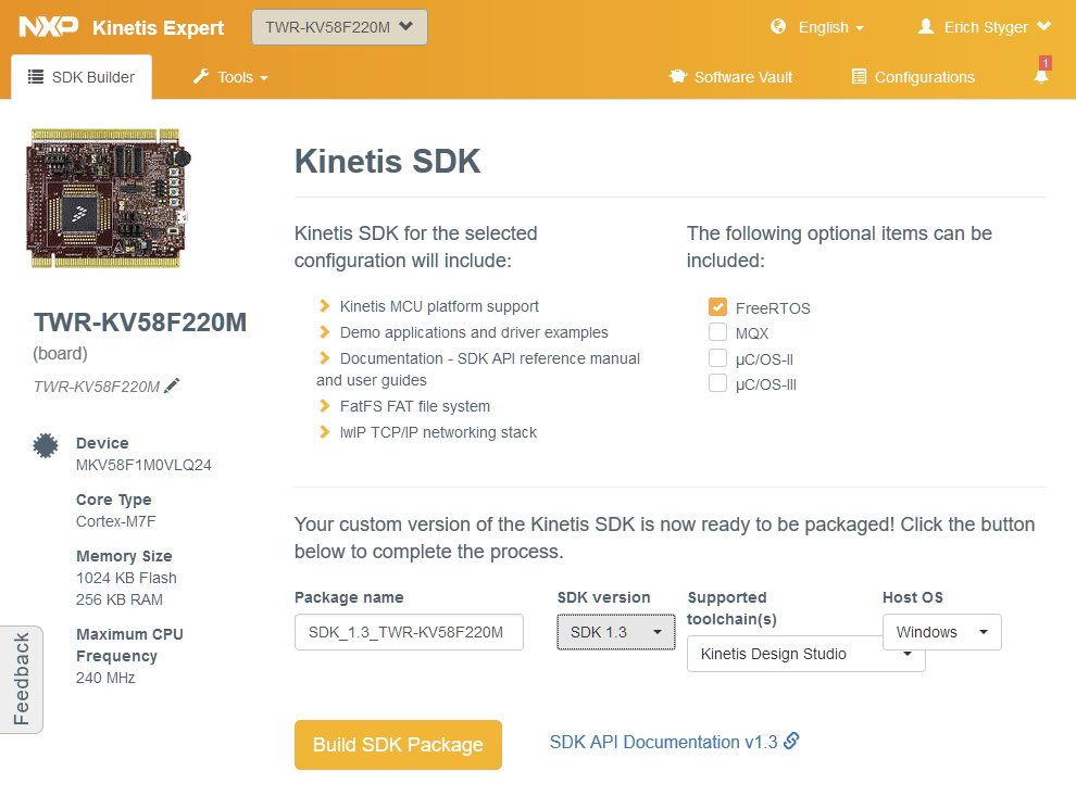
Kinetis SDK for TWR-KV58F220M
As shown above, only the SDK 1.3 is supported (no SDK 2.0 as of today). Which is unfortunate, but the same time I get Processor Expert support for it.
Because there is the SDK V1.3 version of it available on https://kex.nxp.com.
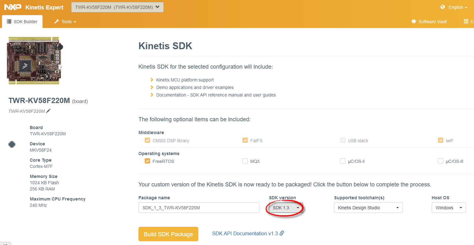
SDK V1.3 for KV58
I installed the package and added the Eclipse update to KDS (menu Help > Install New Software, then use the update archive where you have installed, it (for me it is in C:\nxp\KSDK\SDK_1.3_MKV58F1M0xxx24\tools\eclipse_update)), and with I can create a new project in Eclipse for it:
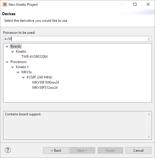
KV58F in Eclipse Wizard
💡 Notice the 240 MHz in some of the documentation. The maximum clock I was able to configure on the TWR-KV58F220M was 220 MHz (that what the 220 indicates). Not sure how to reach 240 MHz?
The generated empty project worked fine, except that I had to add cmsis_gcc.h to the project from the SDK folder structure:
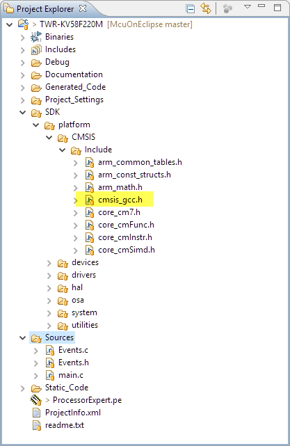
cmsis_gcc.h
FreeRTOS and Kinetis SDK v1.3
I did not use the FreeRTOS which is included in the SDK V1.3, because it is an older version (V8.2.0 instead of the latest V9.0.0, see “FreeRTOS V9.0.0 with Static Memory Allocation“) plus the V8.2.0 in the SDK V1.3 is configured for an M4 and not an M7.
Instead, I used the approach discussed in “Tutorial: Using Processor Expert and FreeRTOS with Kinetis SDK V1.2” and used the McuOnEclipse FreeRTOS:
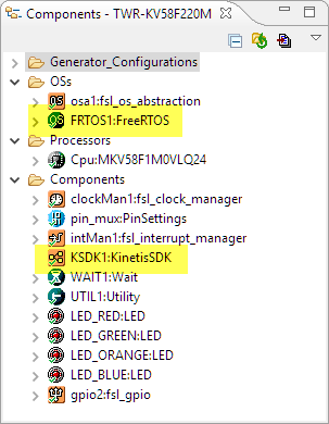
FreeRTOS with Kinetis SDK V1.3
The default fsl_os_abstraction is set to BareMetal with disabled timer:
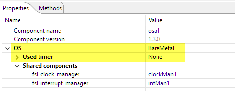
fsl_os_abtracation
FreeRTOS is configured to use the Kinetis SDK:
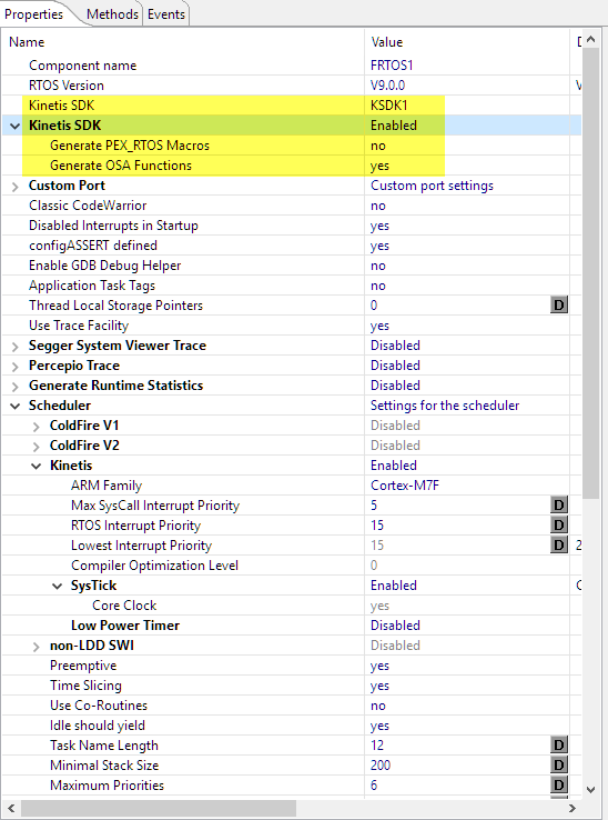
FreeRTOS with Kinetis SDK
The Kinetis SDK component is configured to use the V1.3:
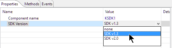
SDK V1.3
LEDs
As a side effort, I have now enabled the SDK_BitIO component to work with the SDK V1.3 too :-):
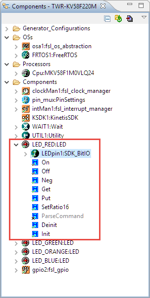
LED component
For the SDK V1.2 it is necessary to give the pin a name, while this is not needed for the SDK V2.0:

Pin Symbol Name
Blinky Tasks
That makes a simple demo with to blinky tasks really simple:
static void blinky_task2(void *param) {
  (void)param;
  for(;;) {
    GPIO_DRV_TogglePinOutput(LED_RED);
    vTaskDelay(100/portTICK_RATE_MS);
    GPIO_DRV_TogglePinOutput(LED_RED);

    GPIO_DRV_TogglePinOutput(LED_GREEN);
    vTaskDelay(100/portTICK_RATE_MS);
    GPIO_DRV_TogglePinOutput(LED_GREEN);
  } /* for */
}

static void blinky_task1(void *param) {
  (void)param;
  for(;;) {
    GPIO_DRV_TogglePinOutput(LED_ORANGE);
    vTaskDelay(50/portTICK_RATE_MS);
    GPIO_DRV_TogglePinOutput(LED_ORANGE);

    GPIO_DRV_TogglePinOutput(LED_BLUE);
    vTaskDelay(50/portTICK_RATE_MS);
    GPIO_DRV_TogglePinOutput(LED_BLUE);
  } /* for */
}

/*lint -save  -e970 Disable MISRA rule (6.3) checking. */
int main(void)
/*lint -restore Enable MISRA rule (6.3) checking. */
{
  /* Write your local variable definition here */

  /*** Processor Expert internal initialization. DON'T REMOVE THIS CODE!!! ***/
  PE_low_level_init();
  /*** End of Processor Expert internal initialization.                    ***/

  /* Write your code here */
  if (xTaskCreate(
      blinky_task1,  /* task function */
      "Blinky1", /* task name for kernel awareness */
      configMINIMAL_STACK_SIZE, /* task stack size */
      (void*)NULL, /* optional task startup argument */
      tskIDLE_PRIORITY,  /* initial priority */
      NULL /* task handle */
    ) != pdPASS) {
    for(;;){} /* error! probably out of memory */
  }
  if (xTaskCreate(
      blinky_task2,  /* task function */
      "Blinky2", /* task name for kernel awareness */
      configMINIMAL_STACK_SIZE, /* task stack size */
      (void*)NULL, /* optional task startup argument */
      tskIDLE_PRIORITY,  /* initial priority */
      NULL /* task handle */
    ) != pdPASS) {
    for(;;){} /* error! probably out of memory */
  }
  /* For example: for(;;) { } */

  /*** Don't write any code pass this line, or it will be deleted during code generation. ***/
  /*** RTOS startup code. Macro PEX_RTOS_START is defined by the RTOS component. DON'T MODIFY THIS CODE!!! ***/
  #ifdef PEX_RTOS_START
    PEX_RTOS_START();                  /* Startup of the selected RTOS. Macro is defined by the RTOS component. */
  #endif
  /*** End of RTOS startup code.  ***/
  /*** Processor Expert end of main routine. DON'T MODIFY THIS CODE!!! ***/
  for(;;){}
  /*** Processor Expert end of main routine. DON'T WRITE CODE BELOW!!! ***/
} /*** End of main routine. DO NOT MODIFY THIS TEXT!!! ***/
And here is the blinky running on the board:
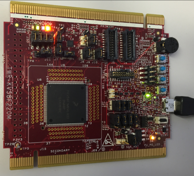
Blinky on TWR-KV58F220M
FreeRTOS Kernel Awareness
FreeRTOS thread awareness with the Segger firmware (see “Adding FreeRTOS Thread Awareness to GDB and Eclipse“) is working too:
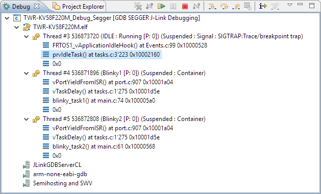
Segger FreeRTOS Thread Awareness
Segger SystemView
I got Segger SystemView working with RTT. The only thing was that the V2.38 was not able to detect the RTT block automatically, so I specified the address of the _SEGGER_RTT symbol in the application manually in the connection settings:
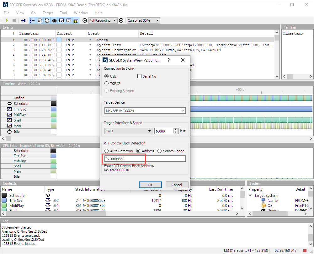
SysView RTT Control Block Detection
With this, the SystemView is working like a charm :-):
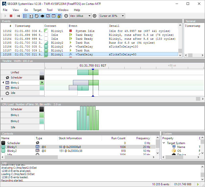
Segger SystemView on Cortex-M7
Summary
It was easy to get FreeRTOS running on that new NXP ARM Cortex-M7F. It is a powerful CPU, I only wish there would be an affordable FRDM board for it. For an evaluation the board provides all the things I need, plus direct access to the CPU pins on the board. Further benchmarks will show if that microcontroller can be used in that project, we will see. But it is a good start to have the software up and running within hours including FreeRTOS.
I have put the project discussed on GitHub.
The updated Processor Expert components to support Cortex-M7 will be available in the next release, probably in a next post.
Happy Cortexing 🙂

Congdatulations!!!
What for do you need such a core?
I surprised that they have license for long time and still have no products(kv5 is on preproduction still). Meanwhile Atmel and ST active on the market.
I’d like to see it in MK-series 🙂 And tqfp package is good too for small batches and manual soldering.
LikeLike
I’m working on drone project which requires both driving multiple motors plus crunching a lot of accelerometer, gyro and magnetometer sensor data. So having a core running at high frequency, lots of Flash and RAM plus dedicated motor control hardware was attractive. Will see how good it fits. And I agree: the Kinetis parts are late with the M7. On the other side the silicon I have is alrady the r0p2 revision, so does not have the issues of the r0p1 version. I think that new core still needs to go through a few silicon revisions. So far it seems working fine, but I have for sure not used many features of the core yet.
LikeLike
Pingback: McuOnEclipse Components: 25-June-2016 Release | MCU on Eclipse
Pingback: McuOnEclipse Components: 31-July-2016 Release | MCU on Eclipse
Pingback: ARM Cortex-M, Interrupts and FreeRTOS: Part 1 | MCU on Eclipse
Pingback: ARM Cortex-M Interrupts and FreeRTOS: Part 3 | MCU on Eclipse
Pingback: MCUXpresso IDE V10.1.0 with i.MX RT1052 Crossover Processor | MCU on Eclipse
Pingback: Be aware: Floating Point Operations on ARM Cortex-M4F | MCU on Eclipse