It has been a while since my first post about the ESP8266 (see “Cheap and Simple WiFi with ESP8266 for the FRDM Board“). The ESP8266 is a new inexpensive ($4.50) WiFi module which makes it easy to connect to the network or internet. Finally this week-end I have found the time to write up a tutorial:
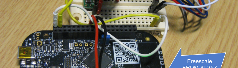
how to implement a WiFi web server for the ESP8266 WiFi module and the Freescale FRDM-KL25Z board:
WSP8266 Web Server

FRDM-KL25Z with ESP8266 WiFi Module
Outline
In this tutorial I’m using a Freescale FRDM-KL25Z board as a web server, using the ESP8266 board. The ESP8266 is a ‘less than $4.5’ WiFi board getting more and more popular as an IoT board. There is even a way to run the ESP8266 standalone (because it has a full processor on that board). However, that development is still in the flux and rather unstable. Instead, I’m using a serial connection to the ESP8266 instead. With this, any small microcontroller can send and receive data from the internet: connect that board to a microcontroller with 3.3V, GND, Tx and Rx, and you have a W-LAN connection!
I’m using in this tutorial Eclipse with GNU/GDB with Processor Expert, but with the steps in this tutorial you should be able to use any other toolchain too.
As things might change in the future with different firmware on the ESP8266: the firmware I’m having on the board is version 00160901.
Board Connections
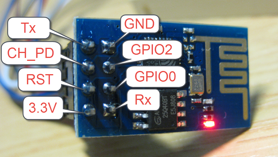
Since my first post on the ESP8266 I have cleaned up the wiring. The pins are as below for the ESP8266:
ESP8266 Pins
Because the ESP8266 can take > 200 mA, I’m using a 5-to-3.3V DC-DC converter. I measured around 70 to 90 mA, so it is not (yet) really needed, but I wanted to use it to protect to board. The ESP8266 Rx and Tx are connected to the microcontroller Tx and Rx pins. A general frustration point for the ESP8266 module is the connection oft the remaining pins. What worked for me is to connect CH_PD to 3.3V and leaving RST, GPIO0 and GPIO2 unconnected/floating.

Wiring Setup with FRDM-KL25Z and ESP8266
Communication Protocol
I recommend to use a logic analyzer to verify the communication between the ESP8266 and the microcontroller. My module communicates with 115200, but I see reports that other modules (other firmware) can use a different baud.
The module uses an AT command send. The simplest command is to send “AT\r\n” and it responds with “AT\r\r\n\r\nOK\r\n”:

AT Command Sent to ESP8266
In this tutorial I’m using a command line shell (see “A Shell for the Freedom KL25Z Board“) to have a manual mode to send commands to the module. More about this later.
Project Creation
You can use my project and source files available on GitHub (see link at the end of this article). Or create your own project. My project is using the Kinetis Design Studio and for the FRDM-KL25Z board (MKL25Z128VLK4).
I have created a project for Processor Expert, as I’m using several components of it:
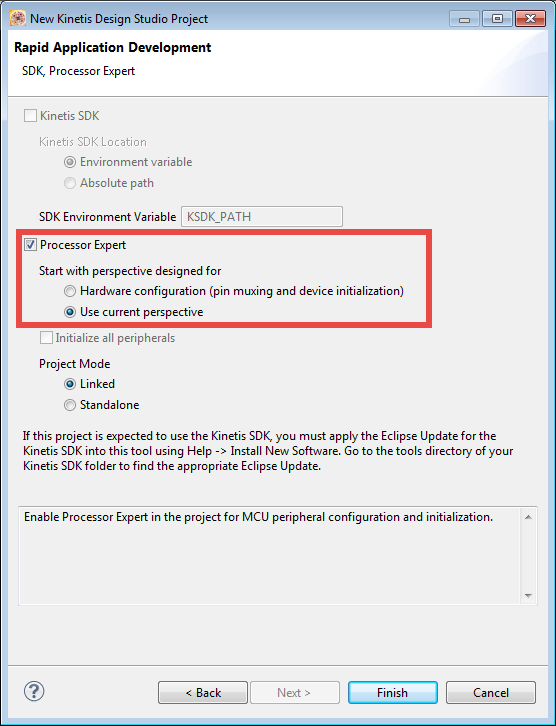
Processor Expert Project
For the project I have several files added:

ESP8266 Project in Eclipse
With the following source files:
- Application.c/.h: This runs the application and web server program
- ESP8266.c/.h: Driver for the ESP8266
- Events.c/.h: Processor Expert event hooks
- main.c: main entry point
- Shell.c/.h: command line interface
Sources
Project and Source files are available on GitHub here:
https://github.com/ErichStyger/mcuoneclipse/tree/master/Examples/KDS/FRDM-KL25Z/FRDM-KL25Z_ESP8266
Please check the latest source files on GitHub. At the time of writing this article, I’m using the following:
Shell.h is the interface to command line shell:
/*
 * Shell.h
 *
 *      Author: Erich Styger
 */

#ifndef SHELL_H_
#define SHELL_H_

/*!
 * \brief Shell parse routine
 */
void SHELL_Parse(void);

/*!
 * \brief Shell initialization
 */
void SHELL_Init(void);

#endif /* SHELL_H_ */
Shell.c implements the application part of the shell:
/*
 * Shell.c
 *
 *      Author: Erich Styger
 */

#include "Shell.h"
#include "CLS1.h"
#include "ESP8266.h"

/* table with shell parser/handler */
static const CLS1_ParseCommandCallback CmdParserTable[] =
{
  CLS1_ParseCommand,
  ESP_ParseCommand,
  NULL /* sentinel */
};

static unsigned char localConsole_buf[48]; /* buffer for command line */

void SHELL_Parse(void) {
  (void)CLS1_ReadAndParseWithCommandTable(localConsole_buf, sizeof(localConsole_buf), CLS1_GetStdio(), CmdParserTable);
}

void SHELL_Init(void) {
  localConsole_buf[0] = '\0'; /* initialize buffer */
}
ESP8266.h is the interface to the WiFi module:
/*
 * ESP8266.h
 *
 *      Author: Erich Styger
 */

#ifndef ESP8266_H_
#define ESP8266_H_

#include "CLS1.h"

#define ESP_DEFAULT_TIMEOUT_MS    (100)
  /*!< Default timeout value in milliseconds */

/*!
 * \brief Command line parser routine
 * \param cmd Pointer to command line string
 * \param handled Return value if command has been handled
 * \param io Standard Shell I/O handler
 * \return Error code, ERR_OK for no failure
 */
uint8_t ESP_ParseCommand(const unsigned char *cmd, bool *handled, const CLS1_StdIOType *io);

/*!
 * \brief Send a string to th ESP8266 module
 * \param str String to send, "\r\n" will be appended
 * \param io Shell I/O handler or NULL if not used
 * \return Error code, ERR_OK for no failure
 */
uint8_t ESP_SendStr(const uint8_t *str, CLS1_ConstStdIOType *io);

/*!
 * \brief Used to send an AT command to the ESP8266 module
 * \param cmd Command string to send
 * \param rxBuf Buffer for the response, can be NULL
 * \param rxBufSize Size of response buffer
 * \param expectedTailStr Expected response from the module, can be NULL
 * \param msTimeout Timeout time in milliseconds
 * \param io Shell I/O handler or NULL if not used
 * \return Error code, ERR_OK for no failure
 */
uint8_t ESP_SendATCommand(uint8_t *cmd, uint8_t *rxBuf, size_t rxBufSize, uint8_t *expectedTailStr, uint16_t msTimeout, const CLS1_StdIOType *io);

/*!
 * \brief Read from the serial line from the module until a sentinel char is received
 * \param buf
 * \param bufSize
 * \param sentinelChar
 * \param timeoutMs Timeout time in milliseconds
 * \return Error code, ERR_OK for no failure
 */
uint8_t ESP_ReadCharsUntil(uint8_t *buf, size_t bufSize, uint8_t sentinelChar, uint16_t timeoutMs);

/*!
 * \brief Sends an AT command to test the connection
 * \return Error code, ERR_OK for no failure
 */
uint8_t ESP_TestAT(void);

/*!
 * \brief Restarts the ESP8266 module
 * \param io Shell I/O handler or NULL if not used
 * \param timeoutMs Timeout time in milliseconds
 * \return Error code, ERR_OK for no failure
 */
uint8_t ESP_Restart(const CLS1_StdIOType *io, uint16_t timeoutMs);

/*!
 * \brief Set the current mode of the module
 * \param mode Where <mode> is 1=Sta, 2=AP or 3=both
 * \return Error code, ERR_OK for no failure
 */
uint8_t ESP_SelectMode(uint8_t mode);

/*!
 * \Brief returns the firmware version string
 * \param fwBuf Buffer for the string
 * \param fwBufSize Size of buffer in bytes
 * \return Error code, ERR_OK for no failure
 */
uint8_t ESP_GetFirmwareVersionString(uint8_t *fwBuf, size_t fwBufSize);

/*!
 * \brief Join an access point.
 * \param ssid SSID of access point
 * \param pwd Password of access point
 * \param nofRetries Number of connection retries
 * \param io Shell I/O or NULL if not used
 * \return Error code, ERR_OK for no failure
 */
uint8_t ESP_JoinAP(const uint8_t *ssid, const uint8_t *pwd, int nofRetries, CLS1_ConstStdIOType *io);

/*!
 * \brief Scans for an IPD message sent by the module
 * \param msgBuf Pointer to the message buffer where to store the message
 * \param msgBufSize Size of message buffer
 * \param ch_id Pointer to where to store the channel/id
 * \param size Pointer where to store the size of the message
 * \param isGet TRUE if it is a GET message, FALSE for a POST message
 * \param timeoutMs Error code, ERR_OK for no failure
 * \param io
 * \return Error code, ERR_OK for no failure
 */
uint8_t ESP_GetIPD(uint8_t *msgBuf, size_t msgBufSize, uint8_t *ch_id, uint16_t *size, bool *isGet, uint16_t timeoutMs, const CLS1_StdIOType *io);

/*!
 * \brief Closes a connection
 * \param channel Channel ID
 * \param io Error code, ERR_OK for no failure
 * \param timeoutMs Error code, ERR_OK for no failure
 * \return Error code, ERR_OK for no failure
 */
uint8_t ESP_CloseConnection(uint8_t channel, const CLS1_StdIOType *io, uint16_t timeoutMs);

/*!
 * \brief Used to determine if the web server is running or not.
 * \return TRUE if web server has beens started
 */
bool ESP_IsServerOn(void);

/*!
 * \brief Driver initialization
 */
void ESP_Init(void);

/*!
 * \brief Driver de-initialization
 */
void ESP_Deinit(void);

#endif /* ESP8266_H_ */
And the ESP8266 driver is in ESP8266.c which implements all the low level SPI access functions, the functional implementation and a command line shell interface:
/*
 * ESP8266.c
 *
 *      Author: Erich Styger
 */

#include "ESP8266.h"
#include "Shell.h"
#include "UTIL1.h"
#include "CLS1.h"
#include "AS2.h"
#include "WAIT1.h"

static bool ESP_WebServerIsOn = FALSE;

bool ESP_IsServerOn(void) {
  return ESP_WebServerIsOn;
}

static void Send(unsigned char *str) {
  while(*str!='\0') {
    AS2_SendChar(*str);
    str++;
  }
}

static void SkipNewLines(const unsigned char **p) {
  while(**p=='\n' || **p=='\r') {
    (*p)++; /* skip new lines */
  }
}

uint8_t ESP_ReadCharsUntil(uint8_t *buf, size_t bufSize, uint8_t sentinelChar, uint16_t timeoutMs) {
  uint8_t ch;
  uint8_t res = ERR_OK;

  if (bufSize<=1) {
    return ERR_OVERRUN; /* buffer to small */
  }
  buf[0] = '\0'; buf[bufSize-1] = '\0'; /* always terminate */
  bufSize--;
  for(;;) { /* breaks */
    if (bufSize==0) {
      res = ERR_OVERRUN;
      break;
    }
    if (AS2_GetCharsInRxBuf()>0) {
      (void)AS2_RecvChar(&ch);
      *buf = ch;
      buf++;
      bufSize--;
      if (ch==sentinelChar) {
        *buf = '\0'; /* terminate string */
        break; /* sentinel found */
      }
    } else {
      if (timeoutMs>10) {
        WAIT1_WaitOSms(5);
        timeoutMs -= 5;
      } else {
        res = ERR_NOTAVAIL; /* timeout */
        break;
      }
    }
  }
  return res;
}

static uint8_t RxResponse(unsigned char *rxBuf, size_t rxBufLength, unsigned char *expectedTail, uint16_t msTimeout) {
  unsigned char ch;
  uint8_t res = ERR_OK;
  unsigned char *p;

  if (rxBufLength < sizeof("x\r\n")) {
    return ERR_OVERFLOW; /* not enough space in buffer */
  }
  p = rxBuf;
  p[0] = '\0';
  for(;;) { /* breaks */
    if (msTimeout == 0) {
      break; /* will decide outside of loop if it is a timeout. */
    } else if (rxBufLength == 0) {
      res = ERR_OVERFLOW; /* not enough space in buffer */
      break;
    } else if (AS2_GetCharsInRxBuf() > 0) {
#if 0
      if (AS2_RecvChar(&ch) != ERR_OK) {
        res = ERR_RXEMPTY;
        break;
      }
#else
      /* might get an overrun OVERRUN_ERR error here? Ignoring error for now */
      (void)AS2_RecvChar(&ch);
#endif
      *p++ = ch;
      *p = '\0'; /* always terminate */
      rxBufLength--;
    } else if (expectedTail!=NULL && expectedTail[0]!='\0'
          && UTIL1_strtailcmp(rxBuf, expectedTail) == 0) {
      break; /* finished */
    } else {
      WAIT1_WaitOSms(1);
      msTimeout--;
    }
  } /* for */
  if (msTimeout==0) { /* timeout! */
    if (expectedTail[0] != '\0' /* timeout, and we expected something: an error for sure */
        || rxBuf[0] == '\0' /* timeout, did not know what to expect, but received nothing? There has to be a response. */
       )
    {
      res = ERR_FAULT;
    }
  }
  return res;
}

uint8_t ESP_SendATCommand(uint8_t *cmd, uint8_t *rxBuf, size_t rxBufSize, uint8_t *expectedTailStr, uint16_t msTimeout, const CLS1_StdIOType *io) {
  uint16_t snt;
  uint8_t res;

  if (rxBuf!=NULL) {
    rxBuf[0] = '\0';
  }
  if (io!=NULL) {
    CLS1_SendStr("sending>>:\r\n", io->stdOut);
    CLS1_SendStr(cmd, io->stdOut);
  }
  if (AS2_SendBlock(cmd, (uint16_t)UTIL1_strlen((char*)cmd), &snt) != ERR_OK) {
    return ERR_FAILED;
  }
  if (rxBuf!=NULL) {
    res = RxResponse(rxBuf, rxBufSize, expectedTailStr, msTimeout);
    if (io!=NULL) {
      CLS1_SendStr("received<<:\r\n", io->stdOut);
      CLS1_SendStr(rxBuf, io->stdOut);
    }
  }
  return res;
}

uint8_t ESP_TestAT(void) {
  /* AT */
  uint8_t rxBuf[sizeof("AT\r\r\n\r\nOK\r\n")];
  uint8_t res;

  res = ESP_SendATCommand("AT\r\n", rxBuf, sizeof(rxBuf), "AT\r\r\n\r\nOK\r\n", ESP_DEFAULT_TIMEOUT_MS, NULL);
  return res;
}

uint8_t ESP_Restart(const CLS1_StdIOType *io, uint16_t timeoutMs) {
  /* AT+RST */
  uint8_t rxBuf[sizeof("AT+RST\r\r\n\r\nOK\r\n")];
  uint8_t res;
  uint8_t buf[64];

  AS2_ClearRxBuf(); /* clear buffer */
  res = ESP_SendATCommand("AT+RST\r\n", rxBuf, sizeof(rxBuf), "AT+RST\r\r\n\r\nOK\r\n", ESP_DEFAULT_TIMEOUT_MS, io);
  if (res==ERR_OK) {
    for(;;) {
      ESP_ReadCharsUntil(buf, sizeof(buf), '\n', 1000);
      if (io!=NULL) {
        CLS1_SendStr(buf, io->stdOut);
      }
      if (UTIL1_strncmp(buf, "ready", sizeof("ready")-1)==0) { /* wait until ready message from module */
        break; /* module has restarted */
      }
    }
  }
  AS2_ClearRxBuf(); /* clear buffer */
  return res;
}

uint8_t ESP_CloseConnection(uint8_t channel, const CLS1_StdIOType *io, uint16_t timeoutMs) {
  /* AT+CIPCLOSE=<channel> */
  uint8_t res;
  uint8_t cmd[64];

  UTIL1_strcpy(cmd, sizeof(cmd), "AT+CIPCLOSE=");
  UTIL1_strcatNum8u(cmd, sizeof(cmd), channel);
  UTIL1_strcat(cmd, sizeof(cmd), "\r\n");
  res = ESP_SendATCommand(cmd, NULL, 0, "Unlink\r\n", timeoutMs, io);
  return res;
}

uint8_t ESP_SetNumberOfConnections(uint8_t nof, const CLS1_StdIOType *io, uint16_t timeoutMs) {
  /* AT+CIPMUX=<nof>, 0: single connection, 1: multiple connections */
  uint8_t res;
  uint8_t cmd[sizeof("AT+CIPMUX=12\r\n")];
  uint8_t rxBuf[sizeof("AT+CIPMUX=12\r\n\r\nOK\r\n")+10];

  if (nof>1) { /* only 0 and 1 allowed */
    if (io!=NULL) {
      CLS1_SendStr("Wrong number of connection parameter!\r\n", io->stdErr);
    }
    return ERR_FAILED;
  }
  UTIL1_strcpy(cmd, sizeof(cmd), "AT+CIPMUX=");
  UTIL1_strcatNum8u(cmd, sizeof(cmd), nof);
  UTIL1_strcat(cmd, sizeof(cmd), "\r\n");
  res = ESP_SendATCommand(cmd, rxBuf, sizeof(rxBuf), "OK\r\n", timeoutMs, io);
  return res;
}

uint8_t ESP_SetServer(bool startIt, uint16_t port, const CLS1_StdIOType *io, uint16_t timeoutMs) {
  /* AT+CIPSERVER=<en>,<port>, where <en>: 0: stop, 1: start */
  uint8_t res;
  uint8_t cmd[sizeof("AT+CIPSERVER=1,80\r\n\r\nOK\r\n")+sizeof("no change")];
  uint8_t rxBuf[sizeof("AT+CIPSERVER=1,80\r\n\r\nOK\r\n")+sizeof("no change")];

  UTIL1_strcpy(cmd, sizeof(cmd), "AT+CIPSERVER=");
  if (startIt) {
    UTIL1_strcat(cmd, sizeof(cmd), "1,");
  } else {
    UTIL1_strcat(cmd, sizeof(cmd), "0,");
  }
  UTIL1_strcatNum16u(cmd, sizeof(cmd), port);
  UTIL1_strcat(cmd, sizeof(cmd), "\r\n");
  res = ESP_SendATCommand(cmd, rxBuf, sizeof(rxBuf), "OK\r\n", timeoutMs, io);
  if (res!=ERR_OK) { /* accept "no change" too */
    UTIL1_strcpy(cmd, sizeof(cmd), "AT+CIPSERVER=");
    if (startIt) {
      UTIL1_strcat(cmd, sizeof(cmd), "1,");
    } else {
      UTIL1_strcat(cmd, sizeof(cmd), "0,");
    }
    UTIL1_strcatNum16u(cmd, sizeof(cmd), port);
    UTIL1_strcat(cmd, sizeof(cmd), "\r\r\nno change\r\n");
    if (UTIL1_strcmp(rxBuf, cmd)==0) {
      res = ERR_OK;
    }
  }
  return res;
}

uint8_t ESP_SelectMode(uint8_t mode) {
  /* AT+CWMODE=<mode>, where <mode> is 1=Sta, 2=AP or 3=both */
  uint8_t txBuf[sizeof("AT+CWMODE=x\r\n")];
  uint8_t rxBuf[sizeof("AT+CWMODE=x\r\r\nno change\r\n")];
  uint8_t expected[sizeof("AT+CWMODE=x\r\r\nno change\r\n")];
  uint8_t res;

  if (mode<1 || mode>3) {
    return ERR_RANGE; /* only 1, 2 or 3 */
  }
  UTIL1_strcpy(txBuf, sizeof(txBuf), "AT+CWMODE=");
  UTIL1_strcatNum16u(txBuf, sizeof(txBuf), mode);
  UTIL1_strcat(txBuf, sizeof(txBuf), "\r\n");
  UTIL1_strcpy(expected, sizeof(expected), "AT+CWMODE=");
  UTIL1_strcatNum16u(expected, sizeof(expected), mode);
  UTIL1_strcat(expected, sizeof(expected), "\r\r\n\n");
  res = ESP_SendATCommand(txBuf, rxBuf, sizeof(rxBuf), expected, ESP_DEFAULT_TIMEOUT_MS, NULL);
  if (res!=ERR_OK) {
    /* answer could be as well "AT+CWMODE=x\r\r\nno change\r\n"!! */
    UTIL1_strcpy(txBuf, sizeof(txBuf), "AT+CWMODE=");
    UTIL1_strcatNum16u(txBuf, sizeof(txBuf), mode);
    UTIL1_strcat(txBuf, sizeof(txBuf), "\r\n");
    UTIL1_strcpy(expected, sizeof(expected), "AT+CWMODE=");
    UTIL1_strcatNum16u(expected, sizeof(expected), mode);
    UTIL1_strcat(expected, sizeof(expected), "\r\r\nno change\r\n");
    if (UTIL1_strcmp(rxBuf, expected)==0) {
      res = ERR_OK;
    }
  }
  return res;
}

uint8_t ESP_GetFirmwareVersionString(uint8_t *fwBuf, size_t fwBufSize) {
  /* AT+GMR */
  uint8_t rxBuf[32];
  uint8_t res;
  const unsigned char *p;

  res = ESP_SendATCommand("AT+GMR\r\n", rxBuf, sizeof(rxBuf), "\r\n\r\nOK\r\n", ESP_DEFAULT_TIMEOUT_MS, NULL);
  if (res!=ERR_OK) {
    if (UTIL1_strtailcmp(rxBuf, "\r\n\r\nOK\r\n")) {
      res = ERR_OK;
    }
  }
  if (res==ERR_OK) {
    if (UTIL1_strncmp(rxBuf, "AT+GMR\r\r\n", sizeof("AT+GMR\r\r\n")-1)==0) { /* check for beginning of response */
      UTIL1_strCutTail(rxBuf, "\r\n\r\nOK\r\n"); /* cut tailing response */
      p = rxBuf+sizeof("AT+GMR\r\r\n")-1;  /* skip beginning */
      UTIL1_strcpy(fwBuf, fwBufSize, p); /* copy firmware information string */
    } else {
      res = ERR_FAILED;
    }
  }
  if (res!=ERR_OK) {
    UTIL1_strcpy(fwBuf, fwBufSize, "ERROR"); /* default error */
  }
  return res;
}

uint8_t ESP_GetIPAddrString(uint8_t *ipBuf, size_t ipBufSize) {
  /* AT+CIFSR */
  uint8_t rxBuf[32];
  uint8_t res;
  const unsigned char *p;

  res = ESP_SendATCommand("AT+CIFSR\r\n", rxBuf, sizeof(rxBuf), NULL, ESP_DEFAULT_TIMEOUT_MS, NULL);
  if (res!=ERR_OK) {
    if (UTIL1_strtailcmp(rxBuf, "\r\n")) {
      res = ERR_OK;
    }
  }
  if (res==ERR_OK) {
    if (UTIL1_strncmp(rxBuf, "AT+CIFSR\r\r\n", sizeof("AT+CIFSR\r\r\n")-1)==0) { /* check for beginning of response */
      UTIL1_strCutTail(rxBuf, "\r\n"); /* cut tailing response */
      p = rxBuf+sizeof("AT+CIFSR\r\r\n")-1; /* skip beginning */
      SkipNewLines(&p);
      UTIL1_strcpy(ipBuf, ipBufSize, p); /* copy IP information string */
    } else {
      res = ERR_FAILED;
    }
  }
  if (res!=ERR_OK) {
    UTIL1_strcpy(ipBuf, ipBufSize, "ERROR");
  }
  return res;
}

uint8_t ESP_GetModeString(uint8_t *buf, size_t bufSize) {
  /* AT+CWMODE? */
  uint8_t rxBuf[32];
  uint8_t res;
  const unsigned char *p;

  res = ESP_SendATCommand("AT+CWMODE?\r\n", rxBuf, sizeof(rxBuf), "\r\n\r\nOK\r\n", ESP_DEFAULT_TIMEOUT_MS, NULL);
  if (res==ERR_OK) {
    if (UTIL1_strncmp(rxBuf, "AT+CWMODE?\r\r\n+CWMODE:", sizeof("AT+CWMODE?\r\r\n+CWMODE:")-1)==0) { /* check for beginning of response */
      UTIL1_strCutTail(rxBuf, "\r\n\r\nOK\r\n"); /* cut tailing response */
      p = rxBuf+sizeof("AT+CWMODE?\r\r\n+CWMODE:")-1; /* skip beginning */
      UTIL1_strcpy(buf, bufSize, p); /* copy information string */
    } else {
      res = ERR_FAILED;
    }
  }
  if (res!=ERR_OK) {
    UTIL1_strcpy(buf, bufSize, "ERROR");
  }
  return res;
}

uint8_t ESP_GetCIPMUXString(uint8_t *cipmuxBuf, size_t cipmuxBufSize) {
  /* AT+CIPMUX? */
  uint8_t rxBuf[32];
  uint8_t res;
  const unsigned char *p;

  res = ESP_SendATCommand("AT+CIPMUX?\r\n", rxBuf, sizeof(rxBuf), "\r\n\r\nOK\r\n", ESP_DEFAULT_TIMEOUT_MS, NULL);
  if (res==ERR_OK) {
    if (UTIL1_strncmp(rxBuf, "AT+CIPMUX?\r\r\n+CIPMUX:", sizeof("AT+CIPMUX?\r\r\n+CIPMUX:")-1)==0) { /* check for beginning of response */
      UTIL1_strCutTail(rxBuf, "\r\n\r\nOK\r\n"); /* cut tailing response */
      p = rxBuf+sizeof("AT+CIPMUX?\r\r\n+CIPMUX:")-1; /* skip beginning */
      UTIL1_strcpy(cipmuxBuf, cipmuxBufSize, p); /* copy IP information string */
    } else {
      res = ERR_FAILED;
    }
  }
  if (res!=ERR_OK) {
    UTIL1_strcpy(cipmuxBuf, cipmuxBufSize, "ERROR");
  }
  return res;
}

uint8_t ESP_GetConnectedAPString(uint8_t *apBuf, size_t apBufSize) {
  /* AT+CWJAP? */
  uint8_t rxBuf[48];
  uint8_t res;
  const unsigned char *p;

  res = ESP_SendATCommand("AT+CWJAP?\r\n", rxBuf, sizeof(rxBuf), "\r\n\r\nOK\r\n", ESP_DEFAULT_TIMEOUT_MS, NULL);
  if (res==ERR_OK) {
    if (UTIL1_strncmp(rxBuf, "AT+CWJAP?\r\r\n+CWJAP:\"", sizeof("AT+CWJAP?\r\r\n+CWJAP:\"")-1)==0) { /* check for beginning of response */
      UTIL1_strCutTail(rxBuf, "\"\r\n\r\nOK\r\n"); /* cut tailing response */
      p = rxBuf+sizeof("AT+CWJAP?\r\r\n+CWJAP:\"")-1; /* skip beginning */
      UTIL1_strcpy(apBuf, apBufSize, p); /* copy IP information string */
    } else {
      res = ERR_FAILED;
    }
  }
  if (res!=ERR_OK) {
    UTIL1_strcpy(apBuf, apBufSize, "ERROR");
  }
  return res;

}

static uint8_t JoinAccessPoint(const uint8_t *ssid, const uint8_t *pwd, CLS1_ConstStdIOType *io) {
  /* AT+CWJAP="<ssid>","<pwd>" */
  uint8_t txBuf[48];
  uint8_t rxBuf[64];
  uint8_t expected[48];

  UTIL1_strcpy(txBuf, sizeof(txBuf), "AT+CWJAP=\"");
  UTIL1_strcat(txBuf, sizeof(txBuf), ssid);
  UTIL1_strcat(txBuf, sizeof(txBuf), "\",\"");
  UTIL1_strcat(txBuf, sizeof(txBuf), pwd);
  UTIL1_strcat(txBuf, sizeof(txBuf), "\"\r\n");

  UTIL1_strcpy(expected, sizeof(expected), "AT+CWJAP=\"");
  UTIL1_strcat(expected, sizeof(expected), ssid);
  UTIL1_strcat(expected, sizeof(expected), "\",\"");
  UTIL1_strcat(expected, sizeof(expected), pwd);
  UTIL1_strcat(expected, sizeof(expected), "\"\r\r\n\r\nOK\r\n");

  return ESP_SendATCommand(txBuf, rxBuf, sizeof(rxBuf), expected, ESP_DEFAULT_TIMEOUT_MS, io);
}

uint8_t ESP_JoinAP(const uint8_t *ssid, const uint8_t *pwd, int nofRetries, CLS1_ConstStdIOType *io) {
  uint8_t buf[32];
  uint8_t res;

  do {
    res = JoinAccessPoint(ssid, pwd, io);
    if (res==ERR_OK) {
      break;
    }
    WAIT1_WaitOSms(1000);
    nofRetries--;
  } while (nofRetries>0);
  return res;
}

static uint8_t ReadIntoIPDBuffer(uint8_t *buf, size_t bufSize, uint8_t *p, uint16_t msgSize, uint16_t msTimeout, const CLS1_StdIOType *io) {
  uint8_t ch;
  size_t nofInBuf;
  int timeout;

  nofInBuf = p-buf;
  bufSize -= nofInBuf; /* take into account what we already have in buffer */
  timeout = msTimeout;
  while (msgSize>0 && bufSize>0) {
    if (AS2_GetCharsInRxBuf()>0) {
      (void)AS2_RecvChar(&ch);
      *p = ch;
      if (io!=NULL) { /* copy on console */
        io->stdOut(ch);
      }
      p++;
      *p = '\0'; /* terminate */
      nofInBuf++; msgSize--; bufSize--;
    } else {
      /* check in case we recveive less characters than expected, happens for POST? */
      if (nofInBuf>6 && UTIL1_strncmp(&p[-6], "\r\nOK\r\n", sizeof("\r\nOK\r\n")-1)==0) {
        break;
      } else {
        timeout -= 10;
        WAIT1_WaitOSms(10);
        if (timeout<0) {
          return ERR_BUSY;
        }
      }
    }
  }
  return ERR_OK;
}

uint8_t ESP_GetIPD(uint8_t *msgBuf, size_t msgBufSize, uint8_t *ch_id, uint16_t *size, bool *isGet, uint16_t timeoutMs, const CLS1_StdIOType *io) {
  /* scan e.g. for
   * +IPD,0,404:POST / HTTP/1.1
   * and return ch_id (0), size (404)
   */
  uint8_t res = ERR_OK;
  const uint8_t *p;
  bool isIPD = FALSE;
  uint8_t cmd[24], rxBuf[48];
  uint16_t ipdSize;

  *ch_id = 0; *size = 0; *isGet = FALSE; /* init */
  for(;;) { /* breaks */
    res = ESP_ReadCharsUntil(msgBuf, msgBufSize, '\n', timeoutMs);
    if (res!=ERR_OK) {
      break; /* timeout */
    }
    if (res==ERR_OK) { /* line read */
      if (io!=NULL) {
        CLS1_SendStr(msgBuf, io->stdOut); /* copy on console */
      }
      isIPD = UTIL1_strncmp(msgBuf, "+IPD,", sizeof("+IPD,")-1)==0;
      if (isIPD) { /* start of IPD message */
        p = msgBuf+sizeof("+IPD,")-1;
        if (UTIL1_ScanDecimal8uNumber(&p, ch_id)!=ERR_OK) {
          if (io!=NULL) {
            CLS1_SendStr("ERR: wrong channel?\r\n", io->stdErr); /* error on console */
          }
          res = ERR_FAILED;
          break;
        }
        if (*p!=',') {
          res = ERR_FAILED;
          break;
        }
        p++; /* skip comma */
        if (UTIL1_ScanDecimal16uNumber(&p, size)!=ERR_OK) {
          if (io!=NULL) {
            CLS1_SendStr("ERR: wrong size?\r\n", io->stdErr); /* error on console */
          }
          res = ERR_FAILED;
          break;
        }
        if (*p!=':') {
          res = ERR_FAILED;
          break;
        }
        ipdSize = p-msgBuf; /* length of "+IPD,<channel>,<size>" string */
        p++; /* skip ':' */
        if (UTIL1_strncmp(p, "GET", sizeof("GET")-1)==0) {
          *isGet = TRUE;
        } else if (UTIL1_strncmp(p, "POST", sizeof("POST")-1)==0) {
          *isGet = FALSE;
        } else {
          res = ERR_FAILED;
        }
        while(*p!='\0') {
          p++; /* skip to the end */
        }
        /* read the rest of the message */
        res = ReadIntoIPDBuffer(msgBuf, msgBufSize, (uint8_t*)p, (*size)-ipdSize, ESP_DEFAULT_TIMEOUT_MS, io);
        break;
      }
    }
  }
  return res;
}

uint8_t ESP_StartWebServer(const CLS1_StdIOType *io) {
  uint8_t buf[32];
  uint8_t res;

  res = ESP_SetNumberOfConnections(1, io, ESP_DEFAULT_TIMEOUT_MS);
  if (res!=ERR_OK) {
    CLS1_SendStr("ERR: failed to set multiple connections.\r\n", io->stdErr);
    return res;
  }
  res = ESP_SetServer(TRUE, 80, io, ESP_DEFAULT_TIMEOUT_MS);
  if (res!=ERR_OK) {
    CLS1_SendStr("ERR: failed to set server.\r\n", io->stdErr);
    return res;
  }
  CLS1_SendStr("INFO: Web Server started, waiting for connection on ", io->stdOut);
  if (ESP_GetIPAddrString(buf, sizeof(buf))==ERR_OK) {
    CLS1_SendStr(buf, io->stdOut);
    CLS1_SendStr(":80", io->stdOut);
  } else {
    CLS1_SendStr("(ERROR!)", io->stdOut);
  }
  CLS1_SendStr("\r\n", io->stdOut);

  return ERR_OK;
}

uint8_t ESP_SendStr(const uint8_t *str, CLS1_ConstStdIOType *io) {
  uint8_t buf[32];
  uint8_t rxBuf[48];
  uint8_t res;
  uint16_t timeoutMs;
  #define RX_TIMEOUT_MS 3000
  AS2_TComData ch;

  UTIL1_strcpy(buf, sizeof(buf), str);
  UTIL1_strcat(buf, sizeof(buf), "\r\n");
  res = ESP_SendATCommand(buf, rxBuf, sizeof(rxBuf), NULL, ESP_DEFAULT_TIMEOUT_MS, io);
  timeoutMs = 0;
  while(timeoutMs<RX_TIMEOUT_MS) {
    WAIT1_WaitOSms(100);
    timeoutMs += 100;
    while (AS2_GetCharsInRxBuf()>0) {
      (void)AS2_RecvChar(&ch);
      CLS1_SendChar(ch);
    }
  }
  return ERR_OK;
}

static uint8_t ESP_PrintHelp(const CLS1_StdIOType *io) {
  CLS1_SendHelpStr("ESP", "ESP8200 commands\r\n", io->stdOut);
  CLS1_SendHelpStr("  help|status", "Print help or status information\r\n", io->stdOut);
  CLS1_SendHelpStr("  send <str>", "Sends a string to the module\r\n", io->stdOut);
  CLS1_SendHelpStr("  test", "Sends a test AT command\r\n", io->stdOut);
  CLS1_SendHelpStr("  restart", "Restart module\r\n", io->stdOut);
  CLS1_SendHelpStr("  listAP", "List available Access Points\r\n", io->stdOut);
  CLS1_SendHelpStr("  connectAP \"ssid\",\"pwd\"", "Connect to an Access Point\r\n", io->stdOut);
  CLS1_SendHelpStr("  server (start|stop)", "Start or stop web server\r\n", io->stdOut);
  return ERR_OK;
}

static uint8_t ESP_PrintStatus(const CLS1_StdIOType *io) {
  uint8_t buf[48];

  CLS1_SendStatusStr("ESP8266", "\r\n", io->stdOut);

  CLS1_SendStatusStr("  Webserver", ESP_WebServerIsOn?"ON\r\n":"OFF\r\n", io->stdOut);

  if (ESP_GetFirmwareVersionString(buf, sizeof(buf)) != ERR_OK) {
    UTIL1_strcpy(buf, sizeof(buf), "FAILED\r\n");
  } else {
    UTIL1_strcat(buf, sizeof(buf), "\r\n");
  }
  CLS1_SendStatusStr("  AT+GMR", buf, io->stdOut);

  if (ESP_GetModeString(buf, sizeof(buf)) != ERR_OK) {
    UTIL1_strcpy(buf, sizeof(buf), "FAILED\r\n");
  } else {
    if (UTIL1_strcmp(buf, "1")==0) {
      UTIL1_strcat(buf, sizeof(buf), " (device)");
    } else if (UTIL1_strcmp(buf, "2")==0) {
      UTIL1_strcat(buf, sizeof(buf), " (AP)");
    } else if (UTIL1_strcmp(buf, "3")==0) {
      UTIL1_strcat(buf, sizeof(buf), " (device+AP)");
    } else {
      UTIL1_strcat(buf, sizeof(buf), " (ERROR)");
    }
    UTIL1_strcat(buf, sizeof(buf), "\r\n");
  }
  CLS1_SendStatusStr("  AT+CWMODE?", buf, io->stdOut);

  if (ESP_GetIPAddrString(buf, sizeof(buf)) != ERR_OK) {
    UTIL1_strcpy(buf, sizeof(buf), "FAILED\r\n");
  } else {
    UTIL1_strcat(buf, sizeof(buf), "\r\n");
  }
  CLS1_SendStatusStr("  AT+CIFSR", buf, io->stdOut);

  if (ESP_GetConnectedAPString(buf, sizeof(buf)) != ERR_OK) {
    UTIL1_strcpy(buf, sizeof(buf), "FAILED\r\n");
  } else {
    UTIL1_strcat(buf, sizeof(buf), "\r\n");
  }
  CLS1_SendStatusStr("  AT+CWJAP?", buf, io->stdOut);

  if (ESP_GetCIPMUXString(buf, sizeof(buf)) != ERR_OK) {
    UTIL1_strcpy(buf, sizeof(buf), "FAILED\r\n");
  } else {
    if (UTIL1_strcmp(buf, "0")==0) {
      UTIL1_strcat(buf, sizeof(buf), " (single connection)");
    } else if (UTIL1_strcmp(buf, "1")==0) {
      UTIL1_strcat(buf, sizeof(buf), " (multiple connections)");
    } else {
      UTIL1_strcat(buf, sizeof(buf), " (ERROR)");
    }
    UTIL1_strcat(buf, sizeof(buf), "\r\n");
  }
  CLS1_SendStatusStr("  CIPMUX", buf, io->stdOut);
  return ERR_OK;
}

uint8_t ESP_ParseCommand(const unsigned char *cmd, bool *handled, const CLS1_StdIOType *io) {
  uint32_t val;
  uint8_t res;
  const unsigned char *p;
  uint8_t pwd[24], ssid[24];

  if (UTIL1_strcmp((char*)cmd, CLS1_CMD_HELP)==0 || UTIL1_strcmp((char*)cmd, "ESP help")==0) {
    *handled = TRUE;
    res = ESP_PrintHelp(io);
  } else if (UTIL1_strcmp((char*)cmd, CLS1_CMD_STATUS)==0 || UTIL1_strcmp((char*)cmd, "ESP status")==0) {
    *handled = TRUE;
    res = ESP_PrintStatus(io);
  } else if (UTIL1_strncmp((char*)cmd, "ESP send ", sizeof("ESP send ")-1)==0) {
    *handled = TRUE;
    p = cmd+sizeof("ESP send ")-1;

    (void)ESP_SendStr(p, io);
  } else if (UTIL1_strcmp((char*)cmd, "ESP test")==0) {
    *handled = TRUE;
    if (ESP_TestAT()!=ERR_OK) {
      CLS1_SendStr("TEST failed!\r\n", io->stdErr);
      res = ERR_FAILED;
    } else {
      CLS1_SendStr("TEST ok!\r\n", io->stdOut);
    }
  } else if (UTIL1_strcmp((char*)cmd, "ESP listAP")==0) {
    *handled = TRUE;
    (void)ESP_SendStr("AT+CWLAP", io);
    /* AT + CWLAP
    response
    + CWLAP: <ecn>, <ssid>, <rssi> [, <mode>]
    OK Or Fails, the return ERROR
    <Ecn> 0 OPEN
    1 WEP
    2 WPA_PSK
    3 WPA2_PSK
    4 WPA_WPA2_PSK
    <Ssid> string parameter, the access point name
    <Rssi> signal strength
    <Mode> 0: manually connect 1: An automatic connection
     */
    return ERR_OK;
  } else if (UTIL1_strncmp((char*)cmd, "ESP connectAP ", sizeof("ESP connectAP ")-1)==0) {
    *handled = TRUE;
    p = cmd+sizeof("ESP connectAP ")-1;
    ssid[0] = '\0'; pwd[0] = '\0';
    res = UTIL1_ScanDoubleQuotedString(&p, ssid, sizeof(ssid));
    if (res==ERR_OK && *p!='\0' && *p==',') {
      p++; /* skip comma */
      res = UTIL1_ScanDoubleQuotedString(&p, pwd, sizeof(pwd));
    } else {
      CLS1_SendStr("Comma expected between strings!\r\n", io->stdErr);
      res = ERR_FAILED;
    }
    if (res==ERR_OK) {
      res = ESP_JoinAP(ssid, pwd, 3, io);
    } else {
      CLS1_SendStr("Wrong command format!\r\n", io->stdErr);
      res = ERR_FAILED;
    }
  } else if (UTIL1_strcmp((char*)cmd, "ESP server start")==0) {
    *handled = TRUE;
    res = ESP_StartWebServer(io);
    ESP_WebServerIsOn = res==ERR_OK;
  } else if (UTIL1_strcmp((char*)cmd, "ESP server stop")==0) {
    *handled = TRUE;
    ESP_WebServerIsOn = FALSE;
  } else if (UTIL1_strcmp((char*)cmd, "ESP restart")==0) {
    *handled = TRUE;
    ESP_Restart(io, 2000);
  }
  return res;
}

void ESP_Deinit(void) {
  /* nothing to do */
}

void ESP_Init(void) {
  AS2_ClearRxBuf(); /* clear buffer */
}
The application interface in Application.h is rather short :-):
/*
 * Application.h
 *
 *      Author: Erich Styger
 */

#ifndef APPLICATION_H_
#define APPLICATION_H_

/*!
 * \brief Application main routine
 */
void APP_Run(void);

#endif /* APPLICATION_H_ */
The main loop of the application is Application.c, along with the application specific web server code.
As the SendWebPage function contains HTML code, I’m posting it here separately:
static uint8_t SendWebPage(uint8_t ch_id, bool ledIsOn, uint8_t temperature, const CLS1_StdIOType *io) {
  static uint8_t http[1024];
  uint8_t cmd[24], rxBuf[48], expected[48];
  uint8_t buf[16];
  uint8_t res = ERR_OK;

  /* construct web page content */
  UTIL1_strcpy(http, sizeof(http), (uint8_t*)"HTTP/1.0 200 OK\r\nContent-Type: text/html\r\nPragma: no-cache\r\n\r\n");
  UTIL1_strcat(http, sizeof(http), (uint8_t*)"<html>\r\n<body>\r\n");
  UTIL1_strcat(http, sizeof(http), (uint8_t*)"<title>ESP8266 Web Server</title>\r\n");
  UTIL1_strcat(http, sizeof(http), (uint8_t*)"<h2>Web Server using ESP8266</h2>\r\n");
  UTIL1_strcat(http, sizeof(http), (uint8_t*)"<br /><hr>\r\n");
  UTIL1_strcat(http, sizeof(http), (uint8_t*)"<p><form method=\"POST\"><strong>Temp: <input type=\"text\" size=2 value=\"");
  UTIL1_strcatNum8s(http, sizeof(http), temperature);
  UTIL1_strcat(http, sizeof(http), (uint8_t*)"\"> <sup>O</sup>C");
  if (ledIsOn) {
    UTIL1_strcat(http, sizeof(http), (uint8_t*)"<p><input type=\"radio\" name=\"radio\" value=\"0\" >Red LED off");
    UTIL1_strcat(http, sizeof(http), (uint8_t*)"<br><input type=\"radio\" name=\"radio\" value=\"1\" checked>Red LED on");
  } else {
    UTIL1_strcat(http, sizeof(http), (uint8_t*)"<p><input type=\"radio\" name=\"radio\" value=\"0\" checked>Red LED off");
    UTIL1_strcat(http, sizeof(http), (uint8_t*)"<br><input type=\"radio\" name=\"radio\" value=\"1\" >Red LED on");
  }
  UTIL1_strcat(http, sizeof(http), (uint8_t*)"</strong><p><input type=\"submit\"></form></span>");
  UTIL1_strcat(http, sizeof(http), (uint8_t*)"</body>\r\n</html>\r\n");

  UTIL1_strcpy(cmd, sizeof(cmd), "AT+CIPSEND="); /* parameters are <ch_id>,<size> */
  UTIL1_strcatNum8u(cmd, sizeof(cmd), ch_id);
  UTIL1_chcat(cmd, sizeof(cmd), ',');
  UTIL1_strcatNum16u(cmd, sizeof(cmd), UTIL1_strlen(http));
  UTIL1_strcpy(expected, sizeof(expected), cmd); /* we expect the echo of our command */
  UTIL1_strcat(expected, sizeof(expected), "\r\r\n> "); /* expect "> " */
  UTIL1_strcat(cmd, sizeof(cmd), "\r\n");
  res = ESP_SendATCommand(cmd, rxBuf, sizeof(rxBuf), expected, ESP_DEFAULT_TIMEOUT_MS, io);
  if (res!=ERR_OK) {
    if (io!=NULL) {
      CLS1_SendStr("INFO: TIMEOUT, closing connection!\r\n", io->stdOut);
    }
  } else {
    if (io!=NULL) {
      CLS1_SendStr("INFO: Sending http page...\r\n", io->stdOut);
    }
    UTIL1_strcat(http, sizeof(http), "\r\n\r\n"); /* need to add this to end the command! */
    res = ESP_SendATCommand(http, NULL, 0, NULL, ESP_DEFAULT_TIMEOUT_MS, io);
    if (res!=ERR_OK) {
      CLS1_SendStr("Sending page failed!\r\n", io->stdErr); /* copy on console */
    } else {
      for(;;) { /* breaks */
        res = ESP_ReadCharsUntil(buf, sizeof(buf), '\n', 1000);
        if (res==ERR_OK) { /* line read */
          if (io!=NULL) {
            CLS1_SendStr(buf, io->stdOut); /* copy on console */
          }
        }
        if (UTIL1_strncmp(buf, "SEND OK\r\n", sizeof("SEND OK\r\n")-1)==0) { /* ok from module */
          break;
        }
      }
    }
  }
  return res;
}
The rest of Application.c is rather simple:
/*
 * Application.c
 *
 *      Author: Erich Styger
 */
#include "PE_Types.h"
#include "CLS1.h"
#include "WAIT1.h"
#include "Shell.h"
#include "UTIL1.h"
#include "ESP8266.h"
#include "LEDR.h"
#include "LEDG.h"
#include "AS2.h"

static uint8_t APP_EspMsgBuf[512]; /* buffer for messages from ESP8266 */

static void WebProcess(void) {
  uint8_t res=ERR_OK;
  bool isGet;
  uint8_t ch_id=0;
  uint16_t size=0;
  const uint8_t *p;
  const CLS1_StdIOType *io;

  if (ESP_IsServerOn()) {
    io = CLS1_GetStdio();
    res = ESP_GetIPD(APP_EspMsgBuf, sizeof(APP_EspMsgBuf), &ch_id, &size, &isGet, 1000, io);
    if (res==ERR_OK) {
      if (isGet) { /* GET: put web page */
        res = SendWebPage(ch_id, LEDR_Get()!=FALSE, 21 /*dummy temperature*/, io);
        if (res!=ERR_OK && io!=NULL) {
          CLS1_SendStr("Sending page failed!\r\n", io->stdErr); /* copy on console */
        }
      } else { /* POST: received info */
        int pos;

        pos = UTIL1_strFind(APP_EspMsgBuf, "radio=");
        if (pos!=-1) { /* found */
          if (UTIL1_strncmp(&APP_EspMsgBuf[pos], "radio=0", sizeof("radio=0")-1)) {
            LEDR_On();
          } else if (UTIL1_strncmp(&APP_EspMsgBuf[pos], "radio=1", sizeof("radio=1")-1)) {
            LEDR_Off();
          }
        }
        res = SendWebPage(ch_id, LEDR_Get()!=FALSE, 20 /*dummy temperature*/, io);
        if (res!=ERR_OK && io!=NULL) {
          CLS1_SendStr("Sending page failed!\r\n", io->stdErr); /* copy on console */
        }
      }
      CLS1_SendStr("INFO: Closing connection...\r\n", io->stdOut);
      res = ESP_CloseConnection(ch_id, io, ESP_DEFAULT_TIMEOUT_MS);
    }
  } else { /* copy messages we receive to console */
    while (AS2_GetCharsInRxBuf()>0) {
      uint8_t ch;

      (void)AS2_RecvChar(&ch);
      CLS1_SendChar(ch);
    }
  }
}

void APP_Run(void) {
  CLS1_ConstStdIOType *io;

  WAIT1_Waitms(1000); /* wait after power-on */
  ESP_Init();
  SHELL_Init();
  io = CLS1_GetStdio();
  CLS1_SendStr("\r\n------------------------------------------\r\n", io->stdOut);
  CLS1_SendStr("ESP8266 with FRDM-KL25Z\r\n", io->stdOut);
  CLS1_SendStr("------------------------------------------\r\n", io->stdOut);
  CLS1_PrintPrompt(io);
  for(;;) {
    WebProcess();
    SHELL_Parse();
    WAIT1_Waitms(10);
    LEDG_Neg();
  }
}
In main.c I call the application part:
/* ###################################################################
**     Filename    : main.c
**     Project     : FRDM-KL25Z_ESP8266
**     Processor   : MKL25Z128VLK4
**     Version     : Driver 01.01
**     Compiler    : GNU C Compiler
**     Date/Time   : 2014-10-15, 14:28, # CodeGen: 0
**     Abstract    :
**         Main module.
**         This module contains user's application code.
**     Settings    :
**     Contents    :
**         No public methods
**
** ###################################################################*/
/*!
** @file main.c
** @version 01.01
** @brief
**         Main module.
**         This module contains user's application code.
*/
/*!
**  @addtogroup main_module main module documentation
**  @{
*/
/* MODULE main */

/* Including needed modules to compile this module/procedure */
#include "Cpu.h"
#include "Events.h"
#include "WAIT1.h"
#include "UTIL1.h"
#include "AS1.h"
#include "ASerialLdd1.h"
#include "CLS1.h"
#include "CS1.h"
#include "AS2.h"
#include "ASerialLdd2.h"
#include "LEDR.h"
#include "LEDpin1.h"
#include "BitIoLdd1.h"
#include "LEDG.h"
#include "LEDpin2.h"
#include "BitIoLdd2.h"
#include "LEDB.h"
#include "LEDpin3.h"
#include "BitIoLdd3.h"
/* Including shared modules, which are used for whole project */
#include "PE_Types.h"
#include "PE_Error.h"
#include "PE_Const.h"
#include "IO_Map.h"
/* User includes (#include below this line is not maintained by Processor Expert) */
#include "Application.h"

/*lint -save  -e970 Disable MISRA rule (6.3) checking. */
int main(void)
/*lint -restore Enable MISRA rule (6.3) checking. */
{
  /* Write your local variable definition here */

  /*** Processor Expert internal initialization. DON'T REMOVE THIS CODE!!! ***/
  PE_low_level_init();
  /*** End of Processor Expert internal initialization.                    ***/

  APP_Run();

  /*** Don't write any code pass this line, or it will be deleted during code generation. ***/
  /*** RTOS startup code. Macro PEX_RTOS_START is defined by the RTOS component. DON'T MODIFY THIS CODE!!! ***/
  #ifdef PEX_RTOS_START
    PEX_RTOS_START();                  /* Startup of the selected RTOS. Macro is defined by the RTOS component. */
  #endif
  /*** End of RTOS startup code.  ***/
  /*** Processor Expert end of main routine. DON'T MODIFY THIS CODE!!! ***/
  for(;;){}
  /*** Processor Expert end of main routine. DON'T WRITE CODE BELOW!!! ***/
} /*** End of main routine. DO NOT MODIFY THIS TEXT!!! ***/

/* END main */
/*!
** @}
*/
/*
** ###################################################################
**
**     This file was created by Processor Expert 10.4 [05.10]
**     for the Freescale Kinetis series of microcontrollers.
**
** ###################################################################
*/
Processor Expert Components
In addition, I’m using several Processor Expert component which are available from SourceForge.

Processor Expert Components
- Wait: Busy waiting component, e.g. to wait for a few milliseconds.
- Utility: string manipulation and utility functions.
- AsynchroSerial (AS1): serial interface to the host for the shell command line interface
- Shell: command line shell implementation
- CriticalSection: for creating critical sections
- AsynchroSerial (AS2): serial interface to the ESP8266 module
- LEDR, LEDG and LEDB: Red, Green and Blue LED on the FRDM-KL25Z board
AS1 is configured as UART connection (over OpenSDA) for the shell:
Shell UART Settings
There are no special settings for the Shell component:
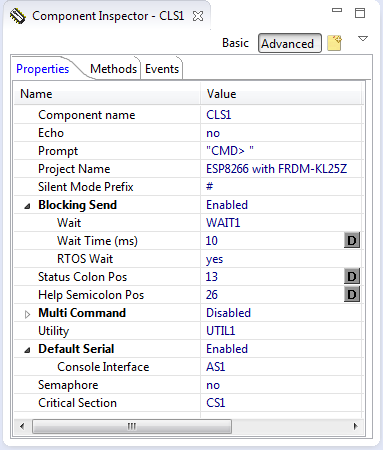
Shell Settings
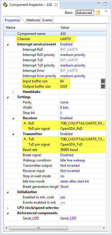
Important are the correct settings to the ESP8266 UART: 115200 baud and using the correct pins on the board connected to the Rx and Tx lines of the ESP8266. I’m using rather large input and output buffers:

UART connection to ESP8266
The LED components are configured for the pins used on the board: PTB18 for red, PTB19 for green and PTD1 for blue LED.

Red LED for FRDM-KL25Z
Sending Commands
The shell implements the command ESP send which I can use to send a string or command to the module:
ESP send <str>
Note that for every command a trailing “\r\n” will be sent.
So instead of using the programmatic way, the shell can be used to ‘manually’ drive a web server, at least most of the part. So I’m using command line commands below to explore how the ESP8266 module works.
Using the Shell
With the project (link to GitHub below), I have a serial connection and command line shell interface to the module. Compile the project and download it to the FRDM-KL25Z board and use a terminal program (I use Termite) to talk with the module.
It power-up, the program shows a greeting message:
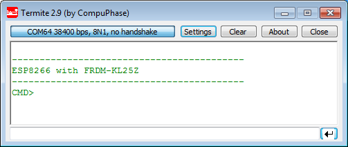
Greeting Message
With ‘help‘ I get a list of the available commands:

Help Command
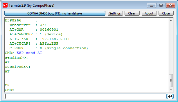
The ‘status‘ command gives a system status:
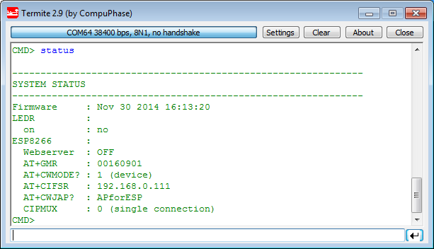
Status Command Output
With this, I’m ready to send commands to the module :-).
Connection Test
To test the connection I send a simple ‘AT’ command
ESP send AT
AT Command Output
and the module should respond with
AT\r\r\n\r\nOK\r\n
Module Restart
Sometimes the module gets stuck. What helps is a power-on reset of the module. Another way is to send the
AT+RST
command to reset the module. The module will boot up and print a ‘ready’ message:
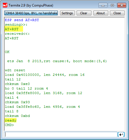
Reset of the ESP8266
Access Point or Device
First I need to configure if the ESP is either a device or an access point. For this, the CWMODE command is used:
AT+CWMODE=
where <mode> is one of:
- 1: ‘Sta’, ESP8266 is a device, it connects to an existing access point
- 2: ‘AP’, ESP8266 is an access point, so other devices can connect to it
- 3: ‘both’. Not really clear to me, but it seems that in this mode the device is in a hybrid mode?
To have the ESP as device so it can connect to an existing access point I use
AT+CWMODE=1
and the module should answer with
AT+CWMODE=1\r\r\n\r\nOK\r\n
or with a ‘no change’:
AT+CWMODE=1\r\r\nno change\r\n
With
AT+CWMODE?
I can ask for the current mode:

Retrieving Current Mode
List of Access Points
With
AT+CWLAP
I get a list of access points. It reports a list like this:
AT+CWLAP

+CWLAP:(0,"",0)
+CWLAP:(4,"APforESP",-39)
+CWLAP:(4,"iza-97497",-94)

OK
❗ I experienced problems with that command in an environment with lots of access points visible. In this case it seems the module hands up. Try first in a place with only a few access points.
For this tutorial I have configured an access point with SSID “APforESP” which shows up in my list.
The list is formatted like this
+ CWLAP: , , [, ]
With following encoding:
<ecn>:
- 0: OPEN
- 1: WPA_PSK
- 2: WPA2_PSK
- 4: WPA_WPA2_PSK
<ssid>: the SSID (string) of the access point.
<rssi>: Signal strength.
<mode>:
- 0: manually connect
- 1: automatic connect
Connecting to Access Point
To connect to an access point I use the command
AT+CWJAP="<ssid>","<pwd>"
Of course replace and with your setup. The module should report back an “OK” message, and you are connected :-).
❗ The module stores the ssid and password. After power-up, the module will automatically reconnect to the Access Point.
IP Address
Once connected I can check the IP address I have been assigned to with
AT+CIFSR
which should give something like
AT+CIFSR

192.168.0.111
So now I know my module IP address :-). With this I can ping my module:

Pinging my ESP Module
Building a Web Server
Now as we hav a connection, it is time to use it to run a web server :-).What I want to serve a web page which I can use to turn on or off the LEDs on the board.
Number of Connections: CIPMUX
Before I start the server I need to make sure it accepts multiple connections. For this I use the following command:
AT+CIPMUX=1
The parameter is either 0 (single connection), or 1 (multiple connections). For a web server I need to set it up for multiple connections.
The ESP module should respond with
AT+CIPMUX=1\r\n\r\nOK\r\n
:info: To make it clear, I have included the ‘\r’ and ‘\n’ in the responses.
Starting the Server: CIPSERVER
I start the server with
AT+CIPSERVER=1,80
The first parameter is either 0 (close connection) or 1 (open connection), followed by the port. I use here the standard http port (80).
The module should answer with:
AT+CIPSERVER=1,80\r\r\n\r\nOK\r\n
or if it is already running the server with a ‘no change’:
AT+CIPSERVER=1,80\r\r\nno change\r\n
No I have a connection open on my IP address (see above: 192.168.0.111), listening to the port I have specified (80).
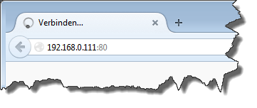
Connecting to the Server with Browser
I enter the IP address in a web browser:
http://192.168.0.111:80
For clarity I have specified the standard HTTP port (80). So if you are using a different port, make sure you specify it in the address line.
Connection from FireFox
The browser now sends a GET request to the module, and I will see this from the message printed out from the module:

First response from Module
The ‘Link’ indicates that it has established a link. IPD (IP Data?) is followed by the channel number (this will the one we have to respond to), plus the size of the following data (296 bytes in that case).
As I’m not responding (yet), there will be a timeout (after about 1 minute or so), with an ‘Unlink’ message from the module:
Link

+IPD,0,296:GET / HTTP/1.1
Host: 192.168.0.111
User-Agent: Mozilla/5.0 (Windows NT 6.1; WOW64; rv:33.0) Gecko/20100101 Firefox/33.0
Accept: text/html,application/xhtml+xml,application/xml;q=0.9,*/*;q=0.8
Accept-Language: de,en-US;q=0.7,en;q=0.3
Accept-Encoding: gzip, deflate
Connection: keep-alive


OK
Unlink

Unlink message
Sending Data to Server: CIPSEND
Now I need to respond and send data to the browser. For this I need to know the channel number, and this is provided in the IPD message from above, right after the comma:
+IPD,0
To send data, I use the command
AT+CIPSEND=<channel>,<size>
So I connect again with the browser, and I send 5 bytes (“hello”) with:
AT+CIPSEND=0,5
The ESP8266 responds with
AT+CIPSEND=0,5\r\n>
Notice the ‘>’ at the end: this is my signal to send the actual data (“hello” in my case):
hello
The ESP8266 now resonds with a SEND OK:

Data Sent
However, the browser is still busy and spins around. I already thought that I did something wrong, but after the browser run into a timeout (after about one minute), my data is there! 🙂

Hello in Browser
Closing Connection: CIPCLOSE
So things *are* working :-). The trick is that I have to close the connection after I have sent the data. There is a CIPCLOSE command I can use:
AT+CIPCLOSE=<channel>
which I can use to close a channel. So I close the connection with
AT+CIPCLOSE=0
and now the browser shows the content right away :-).
Web Server Implementation
So far I have used the module in command line and manual mode. This is great for exploration of the protocol, but for building the web server I need to do this programmatically. For this I run my ‘main’ loop in APP_Run(). After printing a greeting message and initializing the sub modules, it processes the web/module responses, parses the shell command line interfaces and blinks the green (LEDG) LED.
void APP_Run(void) {
  CLS1_ConstStdIOType *io;

  WAIT1_Waitms(1000); /* wait after power-on */
  ESP_Init();
  SHELL_Init();
  io = CLS1_GetStdio();
  CLS1_SendStr("\r\n------------------------------------------\r\n", io->stdOut);
  CLS1_SendStr("ESP8266 with FRDM-KL25Z\r\n", io->stdOut);
  CLS1_SendStr("------------------------------------------\r\n", io->stdOut);
  CLS1_PrintPrompt(io);
  for(;;) {
    WebProcess();
    SHELL_Parse();
    WAIT1_Waitms(10);
    LEDG_Neg();
  }
}
With
ESP server start
I start the web server:
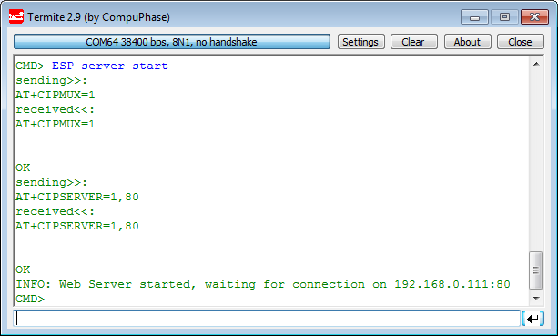
Starting the Web Server
It sends the AT+CIPMUX command followed by the AT+CIPSERVER to start the server, and then listens to the port. Reading and responding messages is done in WebProcess():
static void WebProcess(void) {
  uint8_t res=ERR_OK;
  bool isGet;
  uint8_t ch_id=0;
  uint16_t size=0;
  const uint8_t *p;
  const CLS1_StdIOType *io;

  if (ESP_IsServerOn()) {
    io = CLS1_GetStdio();
    res = ESP_GetIPD(APP_EspMsgBuf, sizeof(APP_EspMsgBuf), &ch_id, &size, &isGet, 1000, io);
    if (res==ERR_OK) {
      if (isGet) { /* GET: put web page */
        res = SendWebPage(ch_id, LEDR_Get()!=FALSE, 21 /*dummy temperature*/, io);
        if (res!=ERR_OK && io!=NULL) {
          CLS1_SendStr("Sending page failed!\r\n", io->stdErr); /* copy on console */
        }
      } else { /* POST: received info */
        int pos;

        pos = UTIL1_strFind(APP_EspMsgBuf, "radio=");
        if (pos!=-1) { /* found */
          if (UTIL1_strncmp(&APP_EspMsgBuf[pos], "radio=0", sizeof("radio=0")-1)) {
            LEDR_On();
          } else if (UTIL1_strncmp(&APP_EspMsgBuf[pos], "radio=1", sizeof("radio=1")-1)) {
            LEDR_Off();
          }
        }
        res = SendWebPage(ch_id, LEDR_Get()!=FALSE, 20 /*dummy temperature*/, io);
        if (res!=ERR_OK && io!=NULL) {
          CLS1_SendStr("Sending page failed!\r\n", io->stdErr); /* copy on console */
        }
      }
      CLS1_SendStr("INFO: Closing connection...\r\n", io->stdOut);
      res = ESP_CloseConnection(ch_id, io, ESP_DEFAULT_TIMEOUT_MS);
    }
  } else { /* copy messages we receive to console */
    while (AS2_GetCharsInRxBuf()>0) {
      uint8_t ch;

      (void)AS2_RecvChar(&ch);
      CLS1_SendChar(ch);
    }
  }
}
If the server is not enabled, it simply copies the received messages to the console:
  } else { /* copy messages we receive to console */
    while (AS2_GetCharsInRxBuf()>0) {
      uint8_t ch;

      (void)AS2_RecvChar(&ch);
      CLS1_SendChar(ch);
    }
  }
Otherwise it scans for an IPD message (ESP_GetIPD()). This function returns the whole message, the channel, the message size and if it is a GET or POST message:
res = ESP_GetIPD(APP_EspMsgBuf, sizeof(APP_EspMsgBuf), &ch_id, &size, &isGet, 1000, io);
If it is a GET message, then it sends a HTML page to the module:
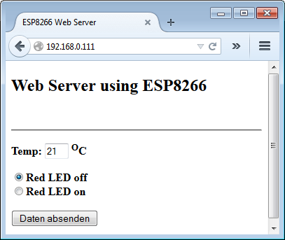
res = SendWebPage(ch_id, LEDR_Get()!=FALSE, 21 /*dummy temperature*/, io);
This web page shows the status of the red LED on the board, a (dummy) temperature value and a button to submit new LED values:
WSP8266 Web Server
The HTML code for this page is constructed in SendWebPage() and sent with AT+CIPSEND:
static uint8_t SendWebPage(uint8_t ch_id, bool ledIsOn, uint8_t temperature, const CLS1_StdIOType *io) {
  static uint8_t http[1024];
  uint8_t cmd[24], rxBuf[48], expected[48];
  uint8_t buf[16];
  uint8_t res = ERR_OK;

  /* construct web page content */
  UTIL1_strcpy(http, sizeof(http), (uint8_t*)"HTTP/1.0 200 OK\r\nContent-Type: text/html\r\nPragma: no-cache\r\n\r\n");
  UTIL1_strcat(http, sizeof(http), (uint8_t*)"<html>\r\n<body>\r\n");
  UTIL1_strcat(http, sizeof(http), (uint8_t*)"<title>ESP8266 Web Server</title>\r\n");
  UTIL1_strcat(http, sizeof(http), (uint8_t*)"<h2>Web Server using ESP8266</h2>\r\n");
  UTIL1_strcat(http, sizeof(http), (uint8_t*)"<br /><hr>\r\n");
  UTIL1_strcat(http, sizeof(http), (uint8_t*)"<p><form method=\"POST\"><strong>Temp: <input type=\"text\" size=2 value=\"");
  UTIL1_strcatNum8s(http, sizeof(http), temperature);
  UTIL1_strcat(http, sizeof(http), (uint8_t*)"\"> <sup>O</sup>C");
  if (ledIsOn) {
    UTIL1_strcat(http, sizeof(http), (uint8_t*)"<p><input type=\"radio\" name=\"radio\" value=\"0\" >Red LED off");
    UTIL1_strcat(http, sizeof(http), (uint8_t*)"<br><input type=\"radio\" name=\"radio\" value=\"1\" checked>Red LED on");
  } else {
    UTIL1_strcat(http, sizeof(http), (uint8_t*)"<p><input type=\"radio\" name=\"radio\" value=\"0\" checked>Red LED off");
    UTIL1_strcat(http, sizeof(http), (uint8_t*)"<br><input type=\"radio\" name=\"radio\" value=\"1\" >Red LED on");
  }
  UTIL1_strcat(http, sizeof(http), (uint8_t*)"</strong><p><input type=\"submit\"></form></span>");
  UTIL1_strcat(http, sizeof(http), (uint8_t*)"</body>\r\n</html>\r\n");

  UTIL1_strcpy(cmd, sizeof(cmd), "AT+CIPSEND="); /* parameters are <ch_id>,<size> */
  UTIL1_strcatNum8u(cmd, sizeof(cmd), ch_id);
  UTIL1_chcat(cmd, sizeof(cmd), ',');
  UTIL1_strcatNum16u(cmd, sizeof(cmd), UTIL1_strlen(http));
  UTIL1_strcpy(expected, sizeof(expected), cmd); /* we expect the echo of our command */
  UTIL1_strcat(expected, sizeof(expected), "\r\r\n> "); /* expect "> " */
  UTIL1_strcat(cmd, sizeof(cmd), "\r\n");
  res = ESP_SendATCommand(cmd, rxBuf, sizeof(rxBuf), expected, ESP_DEFAULT_TIMEOUT_MS, io);
  if (res!=ERR_OK) {
    if (io!=NULL) {
      CLS1_SendStr("INFO: TIMEOUT, closing connection!\r\n", io->stdOut);
    }
  } else {
    if (io!=NULL) {
      CLS1_SendStr("INFO: Sending http page...\r\n", io->stdOut);
    }
    UTIL1_strcat(http, sizeof(http), "\r\n\r\n"); /* need to add this to end the command! */
    res = ESP_SendATCommand(http, NULL, 0, NULL, ESP_DEFAULT_TIMEOUT_MS, io);
    if (res!=ERR_OK) {
      CLS1_SendStr("Sending page failed!\r\n", io->stdErr); /* copy on console */
    } else {
      for(;;) { /* breaks */
        res = ESP_ReadCharsUntil(buf, sizeof(buf), '\n', 1000);
        if (res==ERR_OK) { /* line read */
          if (io!=NULL) {
            CLS1_SendStr(buf, io->stdOut); /* copy on console */
          }
        }
        if (UTIL1_strncmp(buf, "SEND OK\r\n", sizeof("SEND OK\r\n")-1)==0) { /* ok from module */
          break;
        }
      }
    }
  }
  return res;
}
In case of a POST message (user has pressed the button), I scan for the radio element string and turn on/off the LED accordingly, and re-submit the new web page:
      } else { /* POST: received info */
        int pos;

        pos = UTIL1_strFind(APP_EspMsgBuf, "radio=");
        if (pos!=-1) { /* found */
          if (UTIL1_strncmp(&APP_EspMsgBuf[pos], "radio=0", sizeof("radio=0")-1)) {
            LEDR_On();
          } else if (UTIL1_strncmp(&APP_EspMsgBuf[pos], "radio=1", sizeof("radio=1")-1)) {
            LEDR_Off();
          }
        }
        res = SendWebPage(ch_id, LEDR_Get()!=FALSE, 20 /*dummy temperature*/, io);
        if (res!=ERR_OK && io!=NULL) {
          CLS1_SendStr("Sending page failed!\r\n", io->stdErr); /* copy on console */
        }
      }
Finally, it closes the connection at the end:
      CLS1_SendStr("INFO: Closing connection...\r\n", io->stdOut);
      res = ESP_CloseConnection(ch_id, io, ESP_DEFAULT_TIMEOUT_MS);
With this, I handle GET and POST messages and can toggle the LED on my board 🙂 :-).
Summary
It is amazing what is possible with this tiny and inexpensive ($4.50) WiFi module. The simple AT interface allows small and tiny microprocesors to connect to the internet or the local network. With all the hype around ‘Internet of Things’ this is where things very likely will end up: small nodes connecting in an easy way to the network. The processor on that ESP8266 is probably more powerful than the KL25Z (the specs and data sheets of that ESP8266 are still evolving). Or it is possible to run that module in standalone mode too which is a very interesting approach too, see the links at the end of this article. But still having an UART way to connect to the network is very useful and powerful. Other modules costs multiple times more. I expect that many vendors will come up with similar integrated modules e.g. to combine an ARM processor with the WiFi radio, similar that ESP8266 module. For sure that ESP8266 has a head start and paved the way how WiFi connectivity should work. We all will see what the future brings. Until then, that ESP8266 module is something I can use in many projects :-).
The sources and project files can be found on GitHub:
https://github.com/ErichStyger/mcuoneclipse/tree/master/Examples/KDS/FRDM-KL25Z/FRDM-KL25Z_ESP8266
Happy Web-Serving 🙂

Fantastic ! Thanks for providing us such a nice insight into the WiFi module with its working.
LikeLike
You are welcome! I had to search a lot of information in the community and put the puzzle together to make it really working. So I hope that with this information many developers can replicate what I was able to do and be able to hook up their boards to the internet :-).
LikeLike
Yes, of course ! Your hard work definitely will help developers like me & all others out there. The best part is that you are always ready to help. Again thanks for your nice work.
LikeLike
thank you. Your excellent post here has forced me to purchase one of the models.
LikeLike
I hope you do not make me responsible if it does not work ;-). I had ordered my modules several weeks ago from ElectroDragon, and they came with the 00160901 firmware. My module is the V090 hardware (see http://www.electrodragon.com/w/Wi07c#Pin_Wiring_.28V090.29). It could be that your modules have a different firmware, see previous link. I plan to work on an article how to upgrade the firmware if I find time :-).
LikeLike
Hi Erich, I can´t compile this project, the bean UTILITY (command: UTIL1_ScanDoubleQuotedString) not exist on Part1_Beans_16.11.2014.PEupd and Part2_Beans_16.11.2014.PEupd
I think the sourceforge needs to be updated.
LikeLike
I mean the command:UTIL1_ScanDoubleQuotedString does not exist on this version of UTILITY bean.
LikeLike
Hi Luciano,
sorry, my problem :-(. Yes, this is a new function of the Utility component, available on GitHub, but not released on SourceForge.
I have added now the local implementation of it, see https://github.com/ErichStyger/mcuoneclipse/commit/6e7eb5c437dfee17ccac0bb138860815e6deddb0
So you can take that new source file, or add it yourself.
I hope this helps,
Erich
LikeLike
Now it works! I paid $3 each module from China. I will test it soon. Thank you a lot for sharing it!
LikeLike
Hi Luciano,
please let us know the result. I had mine from ElectroDragon ($4.5), from where are yours?
LikeLike
Awesome! where did you get those headers on your Freedom board?
LikeLike
Thanks 🙂
See https://mcuoneclipse.com/2012/10/23/completing-the-frdm-kl25z-board/
LikeLike
Hi, Erich.
What is the part number of the 5-to-3.3V DC-DC converte?
Thanks, Manuel.
LikeLike
Hi Manual,
I use the D24V3F3: http://www.pololu.com/product/2097,
Erich
LikeLike
Thanks for info.
Your website is a gold mine of information.
Manuel.
LikeLike
And check out the latest post about the ESP8266 here: https://mcuoneclipse.com/2014/12/14/tutorial-iot-datalogger-with-esp8266-wifi-module-and-frdm-kl25z/
LikeLike
Pingback: Tutorial: IoT Datalogger with ESP8266 WiFi Module and FRDM-KL25Z | MCU on Eclipse
Hi Erich
I am wondering if you could shed some lights with this PE error. I’m trying to follow your tutorial up to configuring AS2:AsynchroSerial.
The problem is with setting of Baud rate when I select ‘115200 baud’ as value. The error message is:
“Timing setting failed – it is impossible to set the following items: selected value”
Another error field within the same component is Serial_LDD. The only option I am able to select from the dropdown menu is “Serial_LDD”, yet it gave me the following error message:
“Error in the inherited component settings”
Thanks in advance.
Kenno
LikeLike
Hi Kenno,
I guess you have a CPU clock which is too low. Have you increased your core clock to at least 48 MHz (using the external crystal on the FRDM board)?
If not, you cannot reach high baud rates.
Erich
LikeLike
Your guess was correct. So I followed the instruction on your post (https://mcuoneclipse.com/2012/10/27/using-the-8-mhz-crystal-on-the-frdm-kl25z-freedom-board/) to increase the core clock. My board doesn’t have R25 populated, therefore I selected “Low power” as Oscillator operating mode.
After that, I went back to configure the AS2. Unfortunately, the error still presents. Here is the screen shot of my AS2 configuration:
Kenno
LikeLike
Hi Kenno,
you are not using PEE in your screenshot, so I doubt you are at 48 MHz.
See https://mcuoneclipse.com/2012/10/07/tutorial-usb-cdc-with-the-kl25z-freedom-board/ how to get to the maximum clock speed.
Erich
LikeLike
Thanks! I finally got rid of that error after properly configured the CPU core clock. I appologize for the embeding screenshots, didn’t realize that WordPress would display the image from links istead of displaying the actual links.
I can’t wait to finish work, go home and pick up where I left off last night. Your tutorials are great, and I’m learning more and more about Processor Experts from your blog.
Cheers
Kenno
LikeLike
Hi all!
I also purchased a couple of ESP8266 but the modules refused to respond at all, tried every combination possible with the rest if the pins.
After a day, I discovered that my modules came preconfigured with baud(rate) of 9600 so i had to reconfigure to 115200 in order to be able to test your example: AT+IPR=115200
The configuration that worked for me is:
RST, GPIO0, GPIO2 floating
CH_PD connected to 3.3V
Merry Christmas to you all!
Cristian
LikeLike
Hi Cristian,
yes, I saw reports that there are different modules with different firmware, and different baud rates. Can you share from where you ordered your ESP8266 modules? ElectroDragon?
Merry Christmas,
Erich
LikeLike
It was from a local online store that have them on stock, no idea where they source the modules from:
http://www.jola.ro/home/739-wifi-serial-transceiver-esp8266.html
Response to AT+GMR:
AT+GMR
0018000902-AI03
LikeLike
ok, so this one has definitely a different firmware on it. I’m not sure about all the differences, but hopefully the rest of the tuturials are helpful and working for you.
Multumesc,
Erich
LikeLike
where can i find cls1.h?
LikeLike
oh,I find it,need mcuoneclipse components.
and I want to know the diffrenece between McuOnEclipse_PEx and McuOnEclipse component.
LikeLike
ok, good you found it. They are the same, I only moved the component sources to a dedicated GitHub repository, see https://mcuoneclipse.com/2014/11/16/mcuoneclipse-component-sources-in-dedicated-github-repository/
So the McuOnEclipse_PEx ones are the latest and greatest.
LikeLike
Dear Peter
Please help me with this:
I inserted a line into APP_Run(void) {
….
ESP_ParseCommand(“ESP server start”, &handled1, io);
…
for(;;) {
…
}
}
in order to auto-start the web server. This works fine but I want to be able to see the response from this call in the program , it is normally sent to io . How can I redirect the response into a string, buffer in order to analyze it?
La multi ani!
Cristian
LikeLike
Dear Erich!! sorry…
LikeLike
Hi Cristian,
La multi ani!
What you are asking is possible. You simply need to define your own IO handler struct.
See its definition in the Shell:
typedef struct { /* Record containing input, output and error callback (stdin, stdout, stderr). */
CLS1_StdIO_In_FctType stdIn; /* standard input */
CLS1_StdIO_OutErr_FctType stdOut; /* standard output */
CLS1_StdIO_OutErr_FctType stdErr; /* standard error */
CLS1_StdIO_KeyPressed_FctType keyPressed; /* key pressed callback */
} CLS1_StdIOType;
For each of the function pointers, let it point to your own routines. In your own routines, you can do whatever you want, e.g. to store the data in a buffer.
I hope this helps,
Erich
LikeLike
Can you show me what happen when user press button. I am so sory. I cant find it on your tutorial. I am beginer. Thank you a lot
LikeLike
Hi MinhDang,
I have information on button/key press handling here:
I hope this helps.
LikeLike
Hello Erich Styger. Thank you a lot. but my mean is the button on the web page (Data absenden). When i press this button how can my mcu know that. Thank you a gain!!!
LikeLike
Your CPU needs to ask for the data on the server. The CPU has no direct connection to the button.
LikeLike
plese. One more question. Can you show me where is function for ask data from web?
LikeLike
Hi there,
Thank you for your tutorial. It’s very helpful.
One input for you here:
“However, the browser is still busy and spins around. I already thought that I did something wrong, but after the browser run into a timeout (after about one minute), my data is there! ”
It looks like the web browser will wait for the tab to display the webpage. So if you don’t want to wait until it time out, you can add the tab and to your sending string.
For ex:
AT+CIPSEND=0,18\r\n>
hello
It works fine for me in Chrome.
Regards!
LikeLike
opp, the web doesn’t allow me to post the tab % and %
LikeLike
sorry, the tab is html and /html to start and end the webpage.
LikeLike
Hello,
thanks for that tip! Indeed, that seems to solve that problem. It looks like really the whole thing needs to be wrapped into an html …. /html block, and things are much better :-).
LikeLike
hello
its a fantastic module thanks for your explanation.
i only have a question, if i want to use this module as a web server does the ip of the module is static or there is a comand to make it static?
thanks for your time
best regards
LikeLike
The firmware of my module did not support that, or I have not found a way to assign a static IP address. I believe you have to use a different firmware for this.
LikeLike
Hy. I did everything like in the tutorial. I can send commands with AT, and send data to local web server, but I have only a small problem.
I can’t start the web server. If I’m accesing the IP, after starting the server, it appears info with “Conenction OK” and that’s all.
Do I have to do something else, or I’m doing something wrong?
Thank you in advance!
LikeLike
I only can think of that you might have missed a step. Or that you have a module with a different firmware?
LikeLike
It’s seems that the function ESP_GetIPD() doesn’t return the values and in WebProcess() doesn’t enter in the isGet “if”
LikeLike
I suggest you use a logic analyzer to see what is going on on the RX and TX lines. Does the Rx and Tx line make sense?
LikeLike
I don’t have a logic analyzer. The Rx and Tx are working. I get this message when I’m accesing the IP:
Link
+IPD,2,350:GET /favicon.ico HTTP/1.1
Host: 192.168.43.163
Connection: keep-alive
User-Agent: Mozilla/5.0 (Linux; Android 5.1; Nexus 5 Build/LMY47I) AppleWebKit/537.36 (KHTML, like Gecko) Chrome/42.0.2311.111 Mobile Safari/537.36
Accept: */*
Referer: http://192.168.43.163/
Accept-Encoding: gzip, deflate, sdch
Accept-Language: en-US,en;q=0.8,ro;q=0.6
OK
But the WebPage is not displayed. This is the only problem. 🙂
LikeLike
Have you tried a different browser? I had faced a problem that the web page only gets shown if I do a CIPCLOSE. Maybe this is your problem?
LikeLike
I think the problem is in “ReadIntoIPDBuffer()” function. This is returning “ERR_BUSY”, something related with Timeout!
LikeLike
Hello, I was trying to do, but this didn’t work with as1:38400&as2:115200
So I tried to change the baud value to as1:4800&as2:9600 to see if I can access.
below is what I got from the Termite
——————————————
ESP8266 with FRDM-KL25Z
——————————————
CMD> status
————————————————————–
SYSTEM STATUS
————————————————————–
Firmware : May 29 2015 13:20:34
ESP8266 :
Webserver : OFF
AT+GMR : FAILED
AT+CWMODE? : 2 (AP)
AT+CIFSR : 192.168.4.1
OK
AT+CWJAP? : FAILED
CIPMUX : 0 (single connection)
CMD>
—————————————————————–
Is there anyway to fix this problem?
LikeLike
It was like this disconnection below
————————————————————–
SYSTEM STATUS
————————————————————–
Firmware : May 29 2015 13:20:34
ESP8266 :
Webserver : OFF
AT+GMR : FAILED
AT+CWMODE? : FAILED
AT+CIFSR : FAILED
AT+CWJAP? : FAILED
CIPMUX : FAILED
CMD>
LikeLike
Can you checke the RX and TX lines to the module using a logic analyzer or oscilloscope to verify that the communication is working properly? This should give you the necessary information if things are working (or not). I hope this helps.
LikeLike
it is not picking up at signal from TX and RX even though I send signal by AS2. Can it be Chip itself problem?
LikeLike
Have you verified that you have configured AS2 with the correct pin signals? Additionally, are your interrupts enabled, as usually the Asynchroserial communication requires interrupts.
LikeLike
Yes, I even downloaded the code directly from
https://github.com/ErichStyger/mcuoneclipse/tree/master/Examples/KDS/FRDM-KL25Z/FRDM-KL25Z_ESP8266
and copyed the cpu and compents and sources files to load. but it is still showing me like
————————————————————–
SYSTEM STATUS
————————————————————–
Firmware : Jun 1 2015 14:02:05
LEDR :
on : no
ESP8266 :
Webserver : OFF
AT+GMR : FAILED
AT+CWMODE? : FAILED
AT+CIFSR : FAILED
AT+CWJAP? : FAILED
CIPMUX : FAILED
CMD> status
or
when I flip tx and rx pin
————————————————————–
SYSTEM STATUS
————————————————————–
Firmware : Jun 1 2015 13:26:39
LEDR :
on : no
ESP8266 :
Webserver : OFF
AT+GMR : FAILED
AT+CWMODE? : 2 (AP)
AT+CIFSR : 192.168.4.1
OK
AT+CWJAP? : FAILED
CIPMUX : 0 (single connection)
CMD>
LikeLike
The second output looks much better. Have you checked what is going on with RX an TX with a logic analyzer?
LikeLike
when TX is on PTE1 and RX is on PTE0
or I tested with swapping them.
some people said I need to change 115200 to 9600, but it seems same though
LikeLike
Yes, the default baud to the module is 9600 (at least for my modules).
LikeLike
but still the ASY1 should be on 38400 right?
LikeLike
That really might depend on the module firmware you are using. I recommend you use a logic analyzer like the salea one which has an ‘autobaud’ detection: talk with the module with different speeds, and check the baud of the answering module.
LikeLike
so, DO i just power up and connect tx and rx to my saleae?? and try the autobaud??
LikeLike
You need to collect logic analyzer data while the ESP8266 is communicating with your microcontroller.
LikeLike
so I was trying to pick up any logic data signal from PTE0 and PTE1, but nothing is coming out from those two ports. Can anyother thing be a problem? it kinda show me different result when I swap TX and RX connection.
LikeLike
Ohh discard my previous reply. It took some times to take the data from my Saleae logic anal. I can see that it is communicating signal, but it isn’t look like yours.
it is still coming like below
Do I still need autobaud system to check the baud value?
————————————————————–
SYSTEM STATUS
————————————————————–
Firmware : Jun 2 2015 15:22:40
LEDR :
on : no
ESP8266 :
Webserver : OFF
AT+GMR : FAILED
AT+CWMODE? : 2 (AP)
AT+CIFSR : 192.168.4.1
OK
AT+CWJAP? : FAILED
CIPMUX : 0 (single connection)
CMD>
LikeLike
Do you know now with which speed the module is sending data? If yes, you do not need the auto baud. Auto baud helps you to determine the speed. You need to be sure that you are communicating with the module with the correct speed.
LikeLike
Hello, I saw it sends some signal, but wonder which value should I use as the speed.
LikeLike
what kind of speed do you mean?
LikeLike
Hy. I want to control RPM of a DC Motor with the Wifi Module.
I succedded to send data from the wifi web server to microcontroller and set the PWM.
I have an encoder and I want to count the rpm’s but I have some delays from wifi communication. Do you have any idea how can I implement this?
Thanks! 🙂
LikeLike
Your WiFi/network connection will have a latency potentiall in the hundreds of milliseconds. You cannot count the RPMs over a connection with too much latency. So you need to do all the processing locally on the device, and only having things in the web server which can deal with a bigger latency.
LikeLike
Can I count the RPMs for a limited time, for example, for a 0.5-1s, detect RPM and after continue with trasmitting the data in the web server, and repeat the proccess in the main for?
LikeLike
Hi Daniel, that would depend on your system requirements, and how you architect your system. And it will depend on how exactly you measure the RPM too.
LikeLike
Hello.
I am getting confused about how do I make LED webpage like you?
I opened server and I was also able to send message “hello” like 5 characters.
But I am not clear with how I send the code file to control my LED.
could you explain little bit more?
LikeLike
Hi Yonggun Lee,
have a look at the source code of that project (see the link to GitHub at the end of the article).
LikeLike
Hello sir.
Yeah i was looking at it, but… i am not clear of “SendWebPage()” this one.
I was able to transmitting words by declaration “ESP send AT+CIPSEND=0,6” and was able to see “112233”(when I sent ESP send 112233).
But I wonder how I should load “SendWebPage()” this part on the web…
I can see your HTML design file in the code, but wonder how I upload on webpage..
LikeLike
this error occurs after the manually sending message “hello”.
and from there, I also tried to start the server with “ESP server start” and it showed me error. So I command “ESP send AT+RST” to reset and started server but I can see green LED is blinking, but info was showing me wrong IP address information. (What I have is 192.168.1.101:80) but it showed “STAIP,”0.0.0.0:80.
could you figure out what can be the problem?
I was thinking maybe it doesn’t open the server correctly.
or maybe I am not understanding correctly about how to open the WebProcess(LED and Temp one that you made for example).
I am so sorry for bothering you. but please help me.
LikeLike
It seem to me that you have a module with different firmware. Mine only have dynamic IP addresses, and your STAIP let me think that you have a static IP Address. You would first need to configure a valid IP address, otherwise your module is not able to communicate with the network. For this, you need to know/find out the firmware version you are using.
LikeLike
Hello
I was working around little more and iy showed me my STAIP is 192.168.1.101:80. But I couldnt still open the red led webpage thing. Is it still caused by firmware? Or do you know anything can cause the issue? As i mentioned eariler, i can make the webpage to show whatever i send comment.
Thank you sir
LikeLike
Yes, I think something might be different with your firmware. But because I don’t have one which would report STAIP, not sure what the issue could be.
LikeLike
So. The LED example should come out on webpage right after I start the server right?
LikeLike
yes, correct. As soon as you connect to the server with the web browser. Make sure you do a ‘Refresh’ in the browser too.
LikeLike
Seems like i am almost there
Do you know why it is showing below?
”
CMD> ESP server start
sending>>:
AT+CIPMUX=1
received<>:
AT+CIPSERVER=1,80
received<<:
AT+CIPSERVER=1,80
OK
INFO: Web Server started, waiting for connection on (ERROR!)
"
the ERROR! <-??
if I check the IP with AT+CIFSR
it comes right as 192.168.1.104
but when I start the server, it comes as weird as ERROR!
LikeLike
Hello very nice tutorial!!!. I am faced with a strange behavior of esp8266-01, and i would like to ask you if you had any similar behavior when you implement the web server.when I send the data to the browser and I close the connection on channel 0 for example, then the module opens a new channel connection. I read your article but I didn’t see any report to that issue. Do you know what might cause this issue?
Regards Panagiotis
LikeLike
Hi Panagiotis,
are you saying you close the channel from your microcontroller? I have not seen something what you describe with my modules. What version of the firmware are you using?
Erich
LikeLike
Hello Erich
And thank you for your quick reply.I have 2 modules of esp8266-01 The first one has the Ai thinker 0.9.2.4.
The other one has the….
Ai-Thinker Technology Co. Ltd.
AT version:0.21.0.0
SDK version:0.9.5
Which i made the update on my own,because this version supports more useful at commands.
My problem can be found on both versions of the esp’s….. So i think that the particular issue,has not to do with the firmware version.
I set up my module as a server to listen to port 80.When i enter my ip on my browser,i get a message which says +IPD,0,….. mblah mblah…. So i use the CIPSEND command to speak with the browser on channel 0.When i get prompted, i send the data everything ok right now….But when i use CIPCLOSE=0 Then sometimes re-opens the channel 0 but ALWAYS opens a new or more channels… +IPD,1,….. mblah mblah…. +IPD,2,….. mblah mblah…. below is an example….(copy-paste)
0,CONNECT
+IPD,0,343:GET / HTTP/1.1
Host: 192.168.1.104
Connection: keep-alive
Accept: text/html,application/xhtml+xml,application/xml;q=0.9,image/webp,*/*;q=0.8
User-Agent: Mozilla/5.0 (Windows NT 6.1) AppleWebKit/537.36 (KHTML, like Gecko) Chrome/43.0.2357.130 Safari/537.36
Accept-Encoding: gzip, deflate, sdch
Accept-Language: el-GR,el;q=0.8,en;q=0.6
OK
>
SEND OK
1,CONNECT
+IPD,1,315:GET /favicon.ico HTTP/1.1
Host: 192.168.1.104
Connection: keep-alive
User-Agent: Mozilla/5.0 (Windows NT 6.1) AppleWebKit/537.36 (KHTML, like Gecko) Chrome/43.0.2357.130 Safari/537.36
Accept: */*
Referer: http://192.168.1.104/
Accept-Encoding: gzip, deflate, sdch
Accept-Language: el-GR,el;q=0.8,en;q=0.6
0,CLOSED
OK
busy p…
As you can see and you might wonder the responses have changed a little bit.In this version….Until now i haven’t seen yet the reply ‘no this fun’ and i have noticed add-ons
like the 0,CONNECT etc….
To the point…. as you can see it opened a new channel without refreshing my browser or doing anything wrong.Have you ever faced this problem?
I wouldn’t give so much concern to that, but after that the module stucks on a loop and says always the message busy p…
(I bevieve that this module needs lot of improvement…Looking around the net i have seen lot of issues… 😦 )
Regards Panagiotis
LikeLike
Hi Panagiotis,
no, I have not seen such problems. But I have kept my modules with the firmware they have shipped with, and it is a rather old one (need to check the exact version). It looks that I need to be very careful if I decide to upgrade the firmware 😦
LikeLike
Well as I told you I have this issue with both modules.Even with the 0.9.2.4 (Old). So when you close the channel using AT+CIPCLOSE=0 for example you get ‘Unlink’ without the module opening a new +IPD,1 or +IPD,2 for example.Can you made a test and post the result here as I did to spot differences? The new firmware has cool features don’t hesitate to update. The 0,connect had to do with a little bit search I did yesterday with transparent connection for tcp/ip.
Regards Panagiotis
LikeLike
Hello again for those who might expierience the same “problem” as me….. The reason for the new channel creation is because of the browser and not of the ESP module.The browser makes a second GET request, to send back the icon for the page….Look above my posted code.All you have to do is to close the link that was opened and was requesting the favicon.ico….I didn’t know if was ESP’s or browser’s the creation of a new channel id (GET request)…. It turned out that was the browser’s…. (Hope to help someone)
LikeLike
interesting, I had thought about this to be the reason. Thanks for sharing, for shure it will help others!
LikeLike
sorry , can i ask a question?
how can i download your project in KL25Z?
because your project doesn’t have flash.
i refer this tutorial ” https://mcuoneclipse.com/2012/08/02/standalone-flash-programmer/ ”
but in the “Flash File to the Target” is difficulty to me.
can you help me , plz.
LikeLike
Sure, I welcome messages 🙂
Not sure what you mean with ‘doesn’t have flash’? The project is loading the application into the FLASH memory of the KL25Z.
Simply use Kinetis Design Studio, import that project on GitHub and you can use debug to download it to the board.
No need to use ‘Flash File to the Target’ (that article you refer to is for CodeWarrior, not Kinetis Design Studio).
I hope this helps,
Erich
LikeLike
I download the KDS and import projects , component .
When I want to debug , there were many windows .
I don’t know how I pressed.
it becomes an error as shown.
how can i solve it ?
sorry , I have a lot of problems.
thank u .
LikeLike
I download KDS and import project , component .
But when i want to download it to the board , i have a problem.
I don’t know what to press, resulting in a following issue.
how can i solve it .
thanks.
LikeLike
Is this the first time you use Eclipse? I see that the build reported errors (in the bottom in the problems view).
First, you need to be able to compiler/build/link. Have you created Processor Expert code?
LikeLike
Yes , this is my first time using .
I find this video , if I set up a new project , i can download it to the board .But I can’t in the ESP8266 project.
In addition, I can’t find the ” .elf ” file in the debug folder.
How to create Processor Expert code?
LikeLike
It is an older article (for CodeWarrior), but the concepts are still the same. See https://mcuoneclipse.com/2012/09/07/tutorial-enlighting-the-freedom-kl25z-board/ and check section “Generating Code”.
Then do a build. Then you should have that .elf file in your Debug folder.
I hope this helps.
LikeLike
Thank you very much.
I have successfully downloaded it to the board.
Thank.
LikeLike
Sorry problem occurs when I run the terminal.
My problem is in terminal connection.
It would run out of garbled, as shown below.
http://ppt.cc/7cQmK
LikeLike
I think this is a problem of your terminal. Please try Termite: http://www.compuphase.com/software_termite.htm
LikeLike
Still the same after I changed the terminal program.
When I saw Yonggun Lee’s situation above, I guess my question is baud rate.
Like the following condition .
————————————————————–
SYSTEM STATUS
————————————————————–
Firmware : Jul 31 2015 16:10:00
ESP8266 :
Webserver : OFF
AT+GMR : FAILED
AT+CWMODE? : FAILED
AT+CIFSR : FAILED
AT+CWJAP? : FAILED
—————————————————————–
It can be set to a 115200 baud in my UART0 settings.
But it can only be set to a maximum 57600 baud in my UART1 settings.
CIPMUX : FAILED
CMD> ??
——————————————————————–
LikeLike
Yes, different modules/firmware have different firmware. Can you check and verify the baud to the ESP8266 with a scope/logic analyzer?
LikeLike
But Baud can only be set to a maximum 57600 baud in my UART1 settings.
why?
LikeLike
I guess you are not running with 48 MHz bus speed. With 48 MHz as in my example on GitHub I can have 115200 without any problems.
LikeLike
I tried this tutorial, but will stop here aftert after debugging is completed.
——————————————————————
PE_ISR(Cpu_Interrupt)
{
/* This code can be changed using the CPU component property “Build Options / Unhandled int code” */
PE_DEBUGHALT();
}
——————————————————————–
LikeLike
So something triggered an interrupt. Turn on ‘one for every’ (see “https://mcuoneclipse.com/2012/02/20/oh-my-an-interrupt/”). So you know what interrupt has fired. Additionally you might use the Hard Fault component (see “https://mcuoneclipse.com/2012/12/28/a-processor-expert-component-to-help-with-hard-faults/”).
I hope this helps.
LikeLike
Hello Erich,
I’m having a really funny problem with Shell. Everything works fine, but ‘ESP send’ commands don’t work at all. I debugged it, and I found out that the function ESP_ParseCommand isn’t receiving the command properly . I send for example “ESP send AT+CWMODE=1” ,however, I received “ESP send AT” and send an AT command.
I’ve just realized that the problem is with +, when I include + in the String , everything after it isn’t sent to the ESP_ParseCommand. The other commands that you made a specific function (E.g ESP_TestAT , ESP_PrintStatus) work fine . Did you have this problem?
Thank you very much.
Renan.
LikeLike
Hi Renan,
no, that’s new to me. But I had a problem in the Shell after implementing the history function: ‘+’ and other characters were parsed as ‘separation’ characters. But this should have been solved with the latest McuOnEclipse components. Are you using the latest version (2015-07-05) from https://sourceforge.net/projects/mcuoneclipse/files/PEx%20Components/?
LikeLike
Hello Erich,
Once again you saved my day, you’re right. It was the component’s version. I was using a version from 2015-02-03 . Thank you very much. 🙂
LikeLike
Hi Renan,
good, I was hoping it would be as simple as that 🙂
LikeLike
Hello Erich,
I got another problem ,sorry for this. 😦 I did all these steps to start up the server, however, it isn’t working. Everything worked fine, including receiving the message “hello”, but when I tested the web server nothing appeared in the web browser, even though the Shell is showing me the GET requests.
I got this message in my web browser :
“Unable to load the webpage because the server sent no data.”
Do you have any idea what could it be?
Thank you very much.
LikeLike
Hello Erich sorry for bothering you again….Please tell me something…How do you update the value of the temperature?
Do you refresh the whole page or the value of the input box only?
I read that you can accomplish refreshing a input box for example using ajax.
What method do you use?
Regards Panagiotis
LikeLike
Hi Panagiotis,
the update is done with a refresh request from the browser.
Erich
LikeLike
Greetings, i have tested the code with a new ESP8266 module, the Webserver is not appear to work, some debuging told me that the function “ReadIntoIPDBuffer”, always return ERR_BUSY, so the WebProcess is not started completely. not sure how to solve this problem
Firmware details:
AT version:0.25.0.0(Jun 5 2015 16:27:16)
SDK version:1.1.1
Ai-Thinker Technology Co. Ltd.
Jun 5 2015 23:07:20
LikeLike
Hi Joe,
are you using the FRDM-KL25Z with my code? And it looks like your module has a newer firmware I do not have, so maybe this is the problem you have?
LikeLike
Yes im using that board, the WebServer is the only part that is not working, i can use all the other functions without problem, i will continue to work on the problem to see if i can manage the challenge.
LikeLike
SUCCESS!!
Hi have downgraded my module firmware to the same that you are using (not easy work as it seem), and the code is working nicely, the post function only work well in Firefox
So as you said, the newer firmware have an different behaviour with the response of the commands.
the bad part is that i dont have the exact original firmware to come back, but i have find a similar one.
LikeLike
Hi Joe,
glad you have that worked out. Things like this let me run with the original firmware as long as possible. And right now I don’t have time to mess around with a newer firmware, but it looks that maybe I will have to for the future.
Thanks for confirming that this was the problem!
LikeLike
Hi Erich, nice tutorial as usual.
I noticed interrupts are enabled in the PEx but I don’t see any code generated in events.c for the UART interrupts.
thanks
LikeLike
The AsynchroSerial component stores the received character into an internal ring buffer, and does this triggered by the RX interrupt.
There is an OnRxChar() event you can use.
LikeLike
Thanks for your quick response Erich
Joe
LikeLike
Hi Erich,
I try to import your project on Kinetis, but the three LED of the component set throw this error : “No inherited component assigned ; Failed to create component/template : BitIO”. And when I try to add a generic BitIO, I get a “PPAD_PPAD0 undeclared” error. I am starting on this technology, so I don’t know if it’s just a configuration issue or if I need the card to generate Processor Expert Code… (We are 2 developers for one card x)).
LikeLike
Hi Mathieu,
are some components shown grayed out? I believe you have not imported the McuOnEclipse *.PEupd files from SourceForge?
See
LikeLike
Thanks Erich for the reply,
I imported the McuOnEclipse *.PEupd and now I don’t have any problem with the components generation. But after that, when I build the project, I still get the error “PPAD_PPAD0” undeclared.
Thanks for your time.
LikeLike
Hard to tell for me what your problem is. Could you zip and send me your project to the email address mentioned on the About page of this blog?
LikeLike
Hi Erich,
Did you use SPI interface in this module? I would like to configure and start server by AT commands as in your example, but transmit data using SPI. Are you going to make any tutorial about it? There is no much information about it.
Thanks
LikeLike
I have used the serial (uart) interface, not SPI. I’m wondering why you would need SPI?
LikeLike
I want to use SPI to achieve faster transfer of data.
LikeLike
Hi Erich, I’ve made a project similar to this but the website is a little bit mode complex.
when i access it through Chrome, IE or Firefox on Windows, everything works as expected, but when I try to access it through Safari or any other Apple device, it displays the plain html text along with the HTTP header. The header is received in the other browsers under Windows.
Do you have any idea on how to fix it?
Thanks, Stanciu
LikeLike
Hi Stanciu,
I have not used Safari as far as I can remember, I would have to check this. But I would recommend to set a breakpoint/debug it to see what kind of messages are sent to the ESP8266?
Erich
LikeLike
Thank you for the quick reply, but I don’t think that the problem is on the ESP side, as it sends the HTML page back to the browser. I was wondering if you know if iOS is expecting any special header to load the page as html, not plain text. But I will try what you suggested and see if I can find anything wrong
LikeLike
I was just wondering if we could integrate NodeMCU+LUA + AT Commands to do something like this. Connect to the AP, create a webpage in LUA and update the values with AT commands from the shell ? I would later replace the shell with a MicroController feeding data to the Web Page on the ESP8266.
Sorry , I am just a new entrant to this, Just sharing / asking my idea.
LikeLike
Yes, that approach is very possible.
LikeLike
Hi Erich, is there a nice way using PE to bind a shell to a USB CDC device rather than a UART? Thanks, Kevin
LikeLike
Please ignore that question. I’ve engaged my brain!
LikeLike
Hi Kevin,
yes, the ‘Shell’ component has a selection to use USB CDC as communication channel. Using the Shell standard I/O handlers you can use anything, and having multiple channels too.
LikeLike
Hi Erich, a valid question this time. I’ve successfully implemented your example over USB CDC, however, when I request data from the ESP8266, only part of it is received.
For example, if I do a “ESP send AT+GMR” string, I get the following response:
sending>>:end AT+GMR
AT+GMR
received<<:
AT+GMR
AT version:0.40.0.0(Aug 8 2015 14:45:58)
SDK version:1.3.0
Ai-Thinker Technology Co.,Ltd.
Build:1.3*** Failed or unknown command: ESP send AT+GMR
*** Type help to get a list of available commands
whereas I expect this (and I get this when I try the ESP8266 module standalone):
AT+GMR
AT version:0.40.0.0(Aug 8 2015 14:45:58)
SDK version:1.3.0
Ai-Thinker Technology Co.,Ltd.
Build:1.3.0.2 Sep 11 2015 11:48:04
OK
Any clues? Buffer size of the CDC or UART?
Kind regards,
Kevin
LikeLike
Hi Kevin,
I don’t have a ESP with me right now. But I think I know what the problem is: in ESP_SendStr() there is the rxBuf with 48 characters: try to increase that buffer size say to 64.
LikeLike
Hello Erich,
works great. Thank you for this project.
There seems to be some issues with newer Firmware.
I cant connect via AT+CWJAP if the string gets longer than 31 Characters.
ESP connectAp works fine.
There is a Timing probelm with the status command.
The Status is shown as failed before the commands are endend.
ESP8266 :
Webserver : ON
AT+GMR : AT version:1.1.0.0(May ?.
AT+CWMODE? : FAILED
AT+CIFSR : FAILED
AT+CWJAP? : FAILED
CIPMUX : FAILED
CMD> +CIFSR:STAIP,”192.168.1.145″
+CIFSR:STAMAC,”a0:20:a6:12:3a:5c”
OK
AT+CWJAP?
+CWJAP:”kruemel”,”58:6d:8f:98:87:7c”,1,-66
OK
AT+CIPMUX?
+CIPMUX:1
OK
Thanks Eckhard
LikeLike
Ok found ist.
AT+GMR replies now :
AT+GMR
received<<:
AT+GMR
AT version:1.1.0.0(May 11 2016 18:09:56)
SDK version:1.5.4(baaeaebb)
Ai-Thinker Technology Co. Ltd.
Jun 13 2016 11:29:20
OK
Rx Buffer is too small.
Seems to be the same for the Rx Buffer of the other commands.
Got ist working with Rx Buffer up to 140 bytes but Output is still scrambled.
ESP8266 :
Webserver : ON
AT+GMR : AT version:1.1.0.0(May 11 2016 18:09:56)
SDK v AT+CWMODE? : 1 (device)
AT+CIFSR : +CIFSR:STAIP,”192.168.1.145″
+CIFSR:STAMAC,”a0 AT+CWJAP? : kruemel”,”58:6d:8f:98:87:7c”,1,-66
OK
CIPMUX : 1 (multiple connections)
CMD>
LikeLike
Got it working with larger Rx Buffers up to 140 Characters.
Output is still scrambeld .
ESP8266 :
Webserver : ON
AT+GMR : AT version:1.1.0.0(May 11 2016 18:09:56)
SDK v AT+CWMODE? : 1 (device)
AT+CIFSR : +CIFSR:STAIP,”192.168.1.145″
+CIFSR:STAMAC,”a0 AT+CWJAP? : kruemel”,”58:6d:8f:98:87:7c”,1,-66
OK
CIPMUX : 1 (multiple connections)
CMD>
LikeLike
The buffer size depends on the amount of data produced by the module. If you are using the UART in interrupt mode, make sure the interrupt buffers are large enough too.
LikeLike
Hi Erich
Nice project, I only want to know how to auto-start the web server, in order to liberate one UART.
Thanks
LikeLike
Hi Martin,
in that case I think you have to change the firmware in the ESP8266 module.
LikeLike
Hi Erich,
Now i am using ARM cortex M4 series controller and trying to interface ESP8266-01 with this. And for developing i am using eclipse IDE with ARM GCC compiler. using this controller can i send my data to server using this tutorial. I have interface this wifi module with host controller via UART. So i read your tutorial and i like and very helpful for me. So if i add this ESP8266 wifi library and other is it working for me. Is it this wifi library send AT command using UART serial rights?. Please let me know sir.
LikeLike
Yes, it is using AT commands over UART.
LikeLike
hello ,
I follow your tutorial but I have to code using fsl librairie in MCUXPresso ( not Processor Expert)
I impleted the following code to send AT command :
void UART_UserCallback(UART_Type *base, uart_edma_handle_t *handle, status_t status, void *userData)
{
userData = userData;
if (kStatus_UART_TxIdle == status)
{
//txBufferFull = false;
txOnGoing = false;
//UART_WriteBlocking(DEMO_UART,”en cours d’envoi\r\n” , sizeof(“en cours d’envoi\r\n”) – 1);
}
if (kStatus_UART_RxIdle == status)
{
//rxBufferEmpty = false;
rxOnGoing = false;
//UART_WriteBlocking(DEMO_UART,”en cours de reception\r\n” , sizeof(“en cours de reception\r\n” ) – 1);
}
}
uint8_t ESP_SendATcommand(uint8_t *cmd, uint8_t Sizecmd,uint8_t SizeResponse, uint8_t *expectedStr){
uart_transfer_t sendXfer;
uart_transfer_t receiveXfer;
uint8_t res=0;
uint8_t g_rxBuffer[SizeResponse];
if(g_rxBuffer!=NULL){
g_rxBuffer[0]=’\0′;
}
sendXfer.data = cmd;
sendXfer.dataSize =Sizecmd-1;
receiveXfer.data = g_rxBuffer;
receiveXfer.dataSize =SizeResponse-1;
txOnGoing = true;
UART_SendEDMA(WIFI_UART, &g_uartEdmaHandle, &sendXfer);
while (txOnGoing)
{
}
UART_WriteBlocking(DEMO_UART,cmd, Sizecmd – 1);
//UART_ReadBlocking(WIFI_UART, g_rxBuffer,sizeof(“AT+CWMODE=x\r\r\nno change\r\n”)-1 );
rxOnGoing = true;
UART_ReceiveEDMA(WIFI_UART, &g_uartEdmaHandle, &receiveXfer);
while (rxOnGoing)
{
}
delay_ms(100);
UART_WriteBlocking(DEMO_UART,g_rxBuffer , SizeResponse);
if(strcmp((char*)g_rxBuffer,(char*)expectedStr)==0){
res=1;
}
else{
res=0;
}
return res;
}
But I have probleme when I want to read Rx register and I don’t know why ?
The code only works with ( AT test ) ?
LikeLike
Can you try it first with Processor Expert so you are sure you have a working Rx/Tx connection?
LikeLike
I was wondering if ESP8266 could be used as a web server on its own without any extra hardware to host a website that only has two text boxes and a button. What I need is a way to enter my own networks SSID an password from a web browser. Then the ESP8266 will switch to a client mode and connect to my own network using the credentials that I just entered from the web interface. If an extra hardware is needed (I am guessing it is a EEPROM to host the webpage) what would be size?
LikeLike
Yes, you should be able to do this. And you don’t need an external EEPROM as you could store things inside the ESP8266 FLASH memory.
LikeLiked by 1 person
thank you for your response, the code works I can connect to a Access point but the probleme is I can t get the response of the wifi module it gets stuck in the loop :
while (rxOnGoing)
{
}
maybe I have to read the RX one byte by one byte not the all RX register ?
LikeLike
Yes, read the received bytes one by one
LikeLike
Pingback: ESP8266 Tutorial Part I – Getting Started – Tutorial by Cytron
Hi Enrich,
Thanks for this tutorial. I don’t understand, did you use any RTOS? And What is FSShell? Do I use Fsshell with FreeRTOS or standalone mode?
Thanks.
LikeLike
No, this project is not using any RTOS (but it could). It is running bare metal. FSShell is depreciated (stands for File System Shell) and was originally for a file system (FatFS). It has been replaced by the ‘Shell’ component which provides a command line interface to components and everything else. See the project on GitHub: https://github.com/ErichStyger/mcuoneclipse/tree/master/Examples/KDS/FRDM-KL25Z/FRDM-KL25Z_ESP8266
LikeLike