
If you were wondering why I am pushing the FRDM-KL25Z boards hard to the micro-amps, then have a look at this:
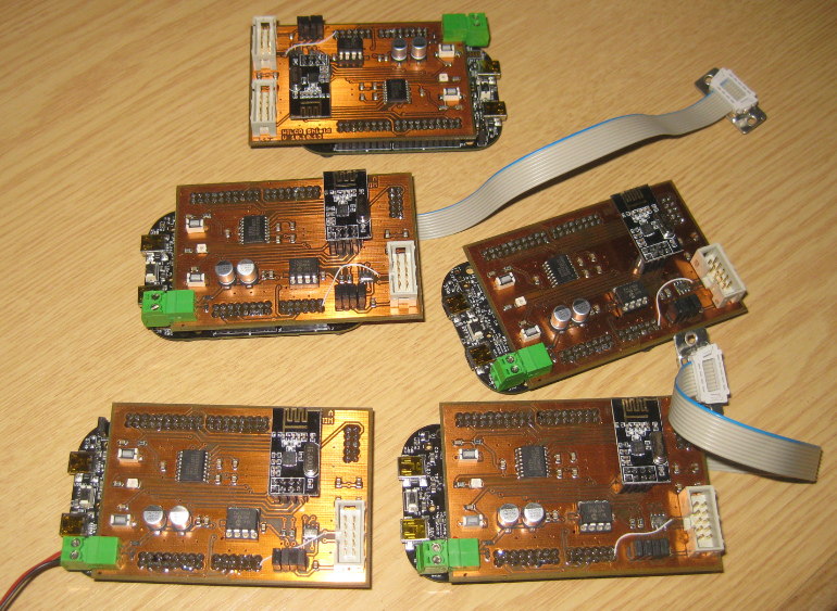
nRF24L01+ Network Nodes
The five boards are the first set of prototypes with a FRDM-KL25Z for a battery operated wireless sensor network based on the nRF24L01+ 2.4GHz transceiver.
The boards are not optimized for size in this stage yet. I plan to make another revision for the FRDM-KL05 or FRDM-KL02Z, as the final application does not need USB functionality, at least not in the leaf nodes. Then things can be moved to a small board with the ARM processor on the same board (so no need for the FRDM board in the final design). But the FRDM boards allow me to make fast prototype rounds so I can concentrate on what is important for the project: to get the wireless sensor nodes up and running :-).

Sensor Node Details
The heart of the sensor node is the 2.4 GHz nRF24L01+ wireless transceiver. A network stack for it is already in progress, and the low-level driver is already available on GitHub. PHY, MAC, NWK and APP are working with initial functionality.
The network stack is using a simple packet format:

Packet Structure
Things are challenging as the nRF24L01+ can send only up to 32 bytes in a single packet over the air. So every byte counts. What works great up to now is simple message sending, including the implementation of a serial-to-wireless (and back) bridge. The application can use standard I/O channels to communicate. This this I can remotely control a sensor node:

Standard IO Channels
The radio packets are passed to the Radio module which implements a state machine. The radio module uses the transceiver interrupts and has internal queues for packet buffering:

Radio Packet Handling
There are two ways of kicking the state machine: either with a local task/thread in the radio module (e.g. with using an RTOS), or with non-blocking Process() calls from the upper layers: that way the stack nicely works both with an RTOS or bare metal :-).
Things are progressing nicely, and once things are sound and stable, I plan to provide it as Processor Expert components: then it will super easy to configure and use it :-).
Happy RFing:-)

Great job! Things are getting better and better.
LikeLike
Well, thanks to you which pointed me to these amazing transceiver modules 🙂
LikeLike
… and BIG thanks to Tom who pointed me to the store in https://mcuoneclipse.com/2013/06/19/using-the-hc-06-bluetooth-module/ !
LikeLike
It looks very exciting. What kind of data can be sent from the sensors? What is the practical range in both RF noisy and RF quiet installations? Will they ever be available for purchase? Thanks, Erich.
LikeLike
Any kind of data can be sent from the sensor nodes, it is up to the application. I can connect analog and digital signals to the pins of the FRDM-KL25Z and send that data. And of course any data from the wireless UART bridge. The RF module offers 250 kBit/s, 1 MBit/s and 2 Mbit/s (I’m using it right now with 250 kBit as according to the data sheet is best in a noisy environment. I have not done any special range or data trhoughput measurement yet. Range depends on the antenna design, and boosters are available for that receiver. But I tested the module with some default values, and ranges are well within a larger room (10-15 meters).
And yes, if there would be enough interest, why not producing a larger batch of PCB’s?
LikeLike
Excellent post, Erich dont stop, I will be look your progress, thanks for sharing
LikeLike
I won’t stop 🙂
LikeLike
Pingback: RNet: A Simple Open Source Radio Network Stack | MCU on Eclipse
Pingback: IEEE802.15.4 for the Zumo Robot | MCU on Eclipse
Pingback: 2014: A Look into the Magic Crystal Ball | MCU on Eclipse
Is there any examples of use LowPower mode without FreeRTOS? For example from normal run mode to LLS mode and wake up every eg. 1s. I use Eclipse and PE with your components.
LikeLike
Sorry, the question is for Low Power post https://mcuoneclipse.com/2013/10/20/tutorial-using-the-frdm-kl25z-as-low-power-board/
LikeLike
What about this post:
Just for you 🙂
I have created it with CodeWarrior, but you can copy/paste the components, or use the settings I have described in the post.
LikeLike
Hi,
Thanks! It was my missing piece 🙂 I tested on my small MKL05 board (made by myself) with Eclipse and works great!
P.S.
I tested this nRF24L01 module with two KL05 also and work fine, but no with arduino RF24 library – maybe I must read through the manual better 🙂 I don’t understand exactly idea of multiple pipe – problem with translate to Polish language probably 🙂
LikeLike
It could be that the Arduino libraries has some bugs too (happened to me). Multiple pipes: have a look at the nRF24L01+ data sheet which explains the concept very well. That should help you.
LikeLike