
If you read my posts, then you probably know: I *love* the FRDM boards! But: Freescale has only the lower-end processors available with a FRDM board (yet?). As I need something more powerful for my Raspberry Pi Camera project, I’m using Tower boards instead. This gives me an ARM Cortex-M4 with 120 MHz, Floating Point unit plus 128 KByte SRAM :-).
For that project I need USB. So this post is about using the TWR-K60F120M and TWR-K70F120M with USB connectivity, using the USB CDC device class as example. Initially I thought I can do as easily with the FRDM boards. It turned out, that things are not that easy.

Freescale TWR-K70F120M Tower Board
The Tower boards are more expensive and larger, but can be combined to ‘tower bricks’. That way more modules as touch LCD (TWR-LCD), Ethernet or USB connector (TWR-SER) can be added:
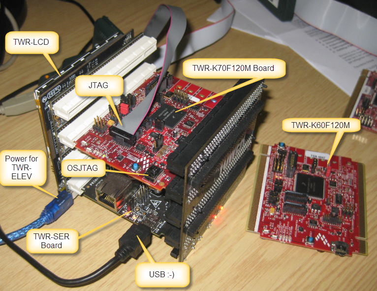
Tower with K70F120M
The TWR processor boards have an onboard debug interface circuit integrated (OSJTAG).
💡 The OSJTAG is a nice feature to start with. However, it is pretty slow and frustrating to work with say if the application is getting larger. I recommend to use an external debug cable (P&E Multilink or Segger J-Link) as they make the tower experience a better one. See this post.
Tool Chain and USB Stack
I’m using in this post CodeWarrior for MCU10.5 with Processor Expert and ARM gcc. Things are pretty generic and apply for other tool chains too (IAR, Keil, or DIY Eclipse). I’m using my own Processor Expert USB component based on the Freescale 4.1.1 USB stack. Modified because it makes adding USB super easy (at least for me 🙂 ) and because the Processor Expert fixes many limitations (and bugs) of the original stack.
💡 Make sure you use the latest and greatest Processor Expert components as described in this post.
TWR-K60F120M Jumper Settings
The picture below shows my jumper settings on the TWR-K60F120M board:

TWR-K60F120 Jumper Settings
The red jumper near the CPU is used for OSJTAG firmware upgrading.
TWR-K70F120M Jumper Settings
The picture below shows the TWR-K70F120M jumper settings I’m using (pretty much the defaults). The red jumper is for upgrading the OSJTAG firmware:
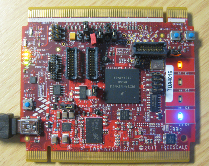
TWR-K70F120M Jumper Settings
TWR-SER Jumper Settings
The board does not have a USB connector for the USB block of the K70. The TWR-SER needs to be used. The picture below shows the jumper settings to use it for USB Device mode:
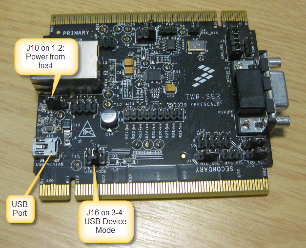
TWR-SER Jumper Settings
USB Clock Configuration
The most important thing for using USB on Freescale devices is the clock configuration! If the clock is not set correctly, then things will not work.
💡 While I have seen projects using the internal clock, everything indicates while this *might* work, it is not working reliably (temperature, clock drift). The Freescale USB block needs a highly accurate 48 MHz clock source. Without it, it is not able to properly oversample the USB signal. Failing providing that accurate clock means that USB does not work.
The TWR-K60F120M and TWR-K70F120M have three different clocks to configure:
- 32 kHz crystal for RTC (Real-Time Clock)
- 50 MHz reference clock (NOT a crystal!)
- 12 MHz crystal
On the TWR-K70F120M the 50 MHz device is on the front side of the board near the CPU, and the 12 MHz and 32 kHz ones are on the back side of the board.
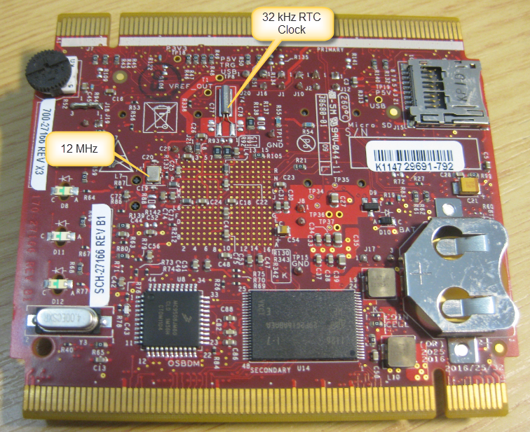
Clocks on TWR-K70F120M Bottom Side
For the TWR-K60F120M the 50 MHz and 12 MHz are on the top side near the CPU, and the 32 kHz one is on the bottom side.

Clocks on TWR-K60F120M Top Side
Both CPU’s can use all three clocks in parallel (with the PLL blocks which is really nice). However, for USB only the 12 MHz clock can be used. I need to generate a 48 MHz clock, and this is not possible with the 50 MHz one :-(.
💡 The clock block of the CPU only can multiply and divide using a power of two.
Project Creation
I have created projects with the CodeWarrior Eclipse ‘New Project Wizard’ for Processor Expert. Links to the projects on GitHub are provided at the end of this article.
K70 USB CDC Project
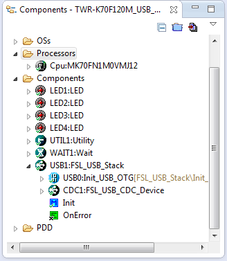
I’m using other components like LED, Utility or Wait which are optional. What is absolutely needed is the FSL_USB_Stack component with the FSL_USB_CDC_Device sub-component which I will show how to configure after the clock settings.
Clock Settings
For USB operation, it is important to configure the clocks properly. I’m configuring all three external clocks, but will only use the 12 MHz one for USB operation. The settings are the same for K60F120 and K70F120, and I’m showing the screenshots below for the K70.
- RTC oscillator: enabled, 32.768 kHz (Value needs to be entered in MHz!)
- System Oscillator 0: Enabled, External reference clock, 50 MHz
- System Oscillator 1: Enabled, External crystal, 12 MHz, Low power

Clock Settings
Next to configure the Clock Source settings.The important thing is that we get a 96 MHz clock. That 96 MHz clock will then be scaled down to 48 MHz for the USB block.
- MCG mode to PEE using PLL 0
- PLL 0 using system oscillator 1 (which we have configured in previous step using the 12 MHz oscillator) and configured to produce a 96 MHz output
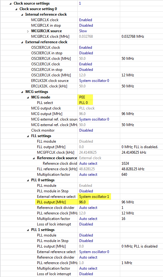
Clock Source Settings
Now I can configure the CPU, bus and flash clocks: I’m using below a 48 MHz CPU and bus clock (Flash clock cannot exceed 25 MHz). The important thing is to configure the PLL/FLL clock to produce the 96 MHz PLL 0 clock:

Clock Configurations
💡 I admit: these devices have very, very complicated clock settings. I wish silicon would be made for easy of use and not complexity ;-). At least with Processor Expert things are much easier to configure.
FSL_USB_Stack Component
Time to add and configure the USB stack. Add the FSL_USB_Stack component to the project (if not already done). Configure it as shown below:
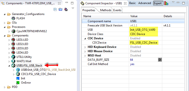
FSL_USB_Stack Configuration
In the FSL_USB_CDC_Device set the CPU you are using (K70 or K60):

FSL_USB_CDC_Device configured for K70
Next to configure the USB Initialization. Important is to enable the clock gate (otherwise the module is not clocked). I use PLL0 clock (which is 96 MHz) and divide it down to 48 MHz:

Init_USB_OTG Configuration
❗ Processor Expert shows a wrong warning about the USB clock frequency. If the clock frequency is showing 48 MHz, you can ignore that bogus warning.
The other settings of the Init_USB_OTG should be already setup correctly, but are shown here for completeness:

Init_USB_OTG other settings
Demo Program
The last step is to generate Processor Expert code, build and try things out. Wait: I need a demo program too! The demo program is very simple: it reads in characters from the USB and echoes it back. I’m using LED’s to show the USB connection status.
static void CDC_Run(void) { int i, cnt = 0; uint32_t val = 0; unsigned char buf[16]; (void)CDC1_SendString((unsigned char*)"Hello world from the KL25Z with USB CDC\r\n"); for(;;) { while(CDC1_App_Task(cdc_buffer, sizeof(cdc_buffer))==ERR_BUSOFF) { /* device not enumerated */ LED1_Neg(); LED2_Off(); WAIT1_Waitms(10); cnt++; if (cnt==100) { LED3_Neg(); cnt = 0; } } LED1_Off(); LED2_Neg(); LED3_Off(); if (CDC1_GetCharsInRxBuf()!=0) { i = 0; while( i<sizeof(in_buffer)-1 && CDC1_GetChar(&in_buffer[i])==ERR_OK ) { i++; } in_buffer[i] = '\0'; (void)CDC1_SendString((unsigned char*)"echo: "); (void)CDC1_SendString(in_buffer); UTIL1_strcpy(buf, sizeof(buf), (unsigned char*)"val: "); UTIL1_strcatNum32u(buf, sizeof(buf), val); UTIL1_strcat(buf, sizeof(buf), (unsigned char*)"\r\n"); (void)CDC1_SendString(buf); val++; } else { WAIT1_Waitms(10); cnt++; if ((cnt%1024)==0) { /* from time to time, write some text */ (void)CDC1_SendString((unsigned char*)"Type some text and it will echo.\r\n"); } } } }Using a terminal program connected to the USB CDC port, this then looks like this (at least for K70):
Example Terminal Session
Problem with K60 Silicon (Mask Set 0N96B)
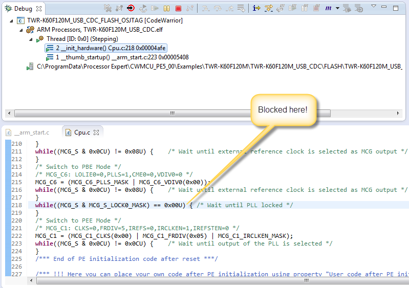
Well, the above things worked very well with the K70 on the TWR-K70F120M board. With the K60 on my TWR-K60F120M board things did not work, and I bumped into a nasty silicon bug :-(. I observed that my code was hanging inside __init_hardware() and waiting until the PLL is locked:
while((MCG_S & MCG_S_LOCK0_MASK) == 0x00U) { /* Wait until PLL locked */ }Wait until PLL locked Problem
I tried many, many things, changed my settings. Nothing worked :-(.
Until I found a hint about the problem I’m facing in the Freescale forum which pointed me to the errata of the Kinetis 0N96B mask set (which indeed is on my board). The particular silicon issue is documented in e3925:
e3925: JTAG/OSC: JTAG enables digital input buffers
The errata was not really clear, and I would not have matched up with my problem. But the forum post indicates the following workaround:
CPU has the mask: 0N96B
Changing RANGE0=2 -> 1 helps, at most cases SW starts.
So I changed two lines from
/* MCG_C7: OSCSEL=0 */ MCG_C7 &= (uint8_t)~(uint8_t)(MCG_C7_OSCSEL_MASK); /* MCG_C10: LOCRE2=0,??=0,RANGE1=2,HGO1=0,EREFS1=1,??=0,??=0 */ MCG_C10 = (MCG_C10_RANGE1(0x02) | MCG_C10_EREFS1_MASK); /* MCG_C2: LOCRE0=0,??=0,RANGE0=2,HGO0=0,EREFS0=0,LP=0,IRCS=0 */ MCG_C2 = MCG_C2_RANGE0(0x02);to this use RANGE1 and RANGE0 with a value of 1 instead of 2:
/* MCG_C7: OSCSEL=0 */ MCG_C7 &= (uint8_t)~(uint8_t)(MCG_C7_OSCSEL_MASK); /* MCG_C10: LOCRE2=0,??=0,RANGE1=1,HGO1=0,EREFS1=1,??=0,??=0 */ MCG_C10 = (MCG_C10_RANGE1(0x01) | MCG_C10_EREFS1_MASK); /* << EST changed range from 0x02 to 0x01 */ /* MCG_C2: LOCRE0=0,??=0,RANGE0=1,HGO0=0,EREFS0=0,LP=0,IRCS=0 */ MCG_C2 = MCG_C2_RANGE0(0x01); /* << EST changed from 0x02 to 0x01 */And indeed: with this my program was not hanging any more and worked :-).
Now as I know what code works, I was looking for a way how to tell Processor Expert to use a range of 1 instead of 2. I have searched for a long time, but have not found anything: so it looks I have no way in Processor Expert to configure this (why??).
Preventing Code Generation
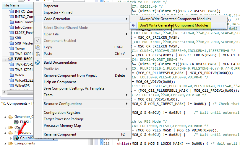
But knowing now that I can fix it manually in the source (file Cpu.c), I need to prevent Processor Expert to revert my change with the next code generation. I already have posted an article about the details on how to disable code generation in Processor Expert. So I disable code generation for the CPU module:
Don’t Write Generated Component Modules
💡 Disabling code generation means that now any other changes of the Cpu component (clock settings, etc) are not reflected in the source code. Then I re-enable code generation again, generate code, make my fix again and then disable code generation again. Painful, but the only way how to deal with such an issue. Same thing if I load a project from a repository and have no code generated yet: I need to enable code generation for the very first time.
Summary
The K60 and K70 are very powerful processors, but clock configuration is both complicated and critical for proper USB operation. I hope the above steps and screenshots make it possible for you to use the boards for USB.
The K60F120M I used has a nasty silicon bug which requires a manual code change to run the clocks properly. Unfortunately I have not found a setting in Processor Expert how to make that workaround. But at least I have a way how to add my patch manually and prevent Processor Expert to revert it. And as a lesson learned: Usually bugs are in my software, but the most nasty bugs are in the silicon :-(. And if you face strange problems, I recommend that you consult the silicon errata information.
All the software is available on GitHub:
Happy USB Clocking 🙂


Hi Erich
I’m able to generate 48 (96) MHz clock from 50 MHz ref clock by PLL.
I’m using K60DN512VLL chip and USB is working.
LikeLike
How did you do that?
LikeLike
I don’t know how to attach the screenshot from CW, but PE allows me to do so.
MGC mode is PEE.
Ref clk divider is 25. So PLL ref clk is 2 MHz.
Then multiplication factor is 48 to get 96 MHz output freq.
LikeLike
ok, I need to try this out once I have access to the board. Many thanks!
LikeLike
Hi Erich,
I installed the PE component for a MK60FN1M0 board I’ve designed and I configured PE as you suggested. The code runs but never enables the DP pullup resistor for full-speed. I can see where it is enabled in USB_DCI_Init() – usb_dci_kinetis.c, but DP remains low. The DP/DM signals are connected to an on-board USB2512 hub which has the hub pulldown resistors. Any ideas? Thanks
LikeLike
Hi Wynn,
let me check the code. One thing I know is that the USB stack itself overwrites the settings from the Init component. Maybe I just need to change that. I’ll check this and let you know.
LikeLike
Hi Wynn,
The problem is indeed that the Freescale USB stack uses its own register inititalization, so the USB Init component settings for pull-ups are overwritten. I have made a change in the USB CDC component with an additional property *not* to use the stack settings, but the ones in the USB Init component. I have been contacted by by Brad (Freescale FAE) on the same subject. I have commited the new feature on GitHub (sources, not in the *.PEupd files yet). I assume Brad will forward you the updated component too. Otherwise I’ll try to contact you directly.
LikeLike
I have a TWR-K60D100M tower system (TWR-SER boards). My goal is to have the CDC interface working inside freeRTOS. I’ve been battling a problem where my computer cannot communicate with my tower system when I add freeRTOS to my project (USB device not recognized). System works fine from the bare-metal example you provide. Any suggestions as to why?
My project can be found at the following github link: https://github.com/tsbiberdorf/K60-USB-CDC.git
Thanks
Terry
LikeLike
Hi Terry,
I checked your github location, but unfortunately the project files are missing. And for now I do not have a TWR-K60D100, only a TWR-K60F120M. I have updated my project on https://github.com/ErichStyger/mcuoneclipse/tree/master/Examples/KDS/TWR-K60F120M so it has now a configuration for FreeRTOS. This works fine with my board (with the exception that my K60F has a silicon bug described in my blog post). You might check my project if there is anything you are missing. Are your tasks running? If the USB is not recognized, then typically this means that the interrupts are not enabled, or that the clock settings are wrong. In my latest USB stack I have an option in the CDC component to either use the USB_Init initialization or the one from the stack. But as you say it it works for bare metal, this is probably not the problem. The other thing is that you might not process frequently the USB functions from your task? Again, have a look at my example. I hope this helps.
LikeLike
Hi Erich,
My apologies to have to pester you again… Under your tutelage I was able to get a DIY GNU ARM toolchain with PEx within Eclipse up and running. In order to try out the new dev setup I thought the sensible thing to do would be clone your git repo and build and flash this USB example to my twr-k60f120m hardware. Unfortunately, it would seem that the examples that form the basis of this blog post require /ARM_GCC_Support/ewl/* which I presume is the Freescale code warrior libraries in addition to your previously mentioned component libraries?
TIA
LikeLike
Hi Mat,
yes, that project had been created with CodeWarrior for MCU10.5. The GNU ARM toolchain is using a different project file/settings.
The project should not need the ewl libraries (at least not directly), but I have not made a port to the Eclipse Kepler+GNU ARM Eclipse plugins.
LikeLike
Thanks for these USB tutorials. I found your git example for the TWR-k20d72m board and was able to get it up and running relatively quickly. The only modification that I made was that I kept the processor core clock at 72 MHz and then set USBDIV=1 and USBFRAC=1 to generate the 48 Mhz USB clock.
LikeLike
I Erich, I want to probe an example project (blinky led) with codewarrior 10.6 into the board. When I debug the project with Pne U-MultiLink I get an error message: “The embedded firmware needs to be in bootloader mode to update. Please unplug the USB cable, insert a jumper on the 2-pin bootloader header (connecting JM60 IRQ to ground), and reconnect the USB cable.”
I have already jumped the J10 pin but when I run it agian, it throws other error saying that the board is in bootloader mode. I want to get in the debugger mode to download the example to the board. What am i doing wrong?
LikeLike
After updating the board, you need to remove that bootloader jumper. I have received today a similar question from a student (different board), so I will write a step-by-step tutorial tonight and publish it on the blog.
LikeLike
that’s from the K60 board. But I need the SoC of K70, I looked at http://www.freescale.com/webapp/sps/site/prod_summary.jsp?code=TWR-K70F120M&fpsp=1&tab=Documentation_Tab and there is any reference manual.
LikeLike
Hi Juan,
have a look at https://mcuoneclipse.com/2014/07/07/step-by-step-updating-osbdmosjtag-debug-firmware/
I hope this helps,
Erich
LikeLike
I will look it! thanks 4 all!
LikeLike
Hi Erich, I do not found a datasheet that explain what is and what should have any register for K70F120M. I looked at the official page and i found nothing. Do you know a datasheet? Secondly, I see at this post that you created a LED component,I’m using codewarrior 10.6 and I do not found the way to create it. Thanks.
LikeLike
About the registers: you should find the SoC register description in the Reference Manual (RM) available under the documentation tap on the Freescale web site for that device.
As for the LED component: this is one of the many components which are published with the MCUonEclipse project, see https://mcuoneclipse.com/2013/05/09/processor-expert-component-peupd-files-on-github/ how to get and install them.
LikeLike
Thanks for the components, I going to download them. About the SoC, I looked at the Freescale site where you say and I did not found it.
LikeLike
Go for example to
http://www.freescale.com/webapp/sps/site/prod_summary.jsp?code=K60_120&fpsp=1&tab=Documentation_Tab
And then it is
Click to access K60P144M150SF3RM.pdf
On the left side there should be a category ‘Reference manual’ under the category ‘Application notes’
LikeLike
I posted at a wrong place. Going to paste the same here. Sory
that’s from the K60 board. But I need the SoC of K70, I looked at http://www.freescale.com/webapp/sps/site/prod_summary.jsp?code=TWR-K70F120M&fpsp=1&tab=Documentation_Tab and there is any reference manual.
LikeLike
Hi Juan,
So it is for MK70FN1M0VMJ12? Then enter that into the search field on freescale.com, and you will get a search result for a bunch of PDF documents, including the reference manual:
Click to access K70P256M150SF3RM.pdf
Erich
LikeLike
That’s for the version of 150MHz. I have of 120MHz. It’s the same manual?
LikeLike
I think it is is the same. Otherwise you have to search the Freescale web site to see if there is a 150 MHz manual.
LikeLike
Hi Erich, I have a question. I could debug a program on my K70 board, and it’s ok. But when I press RUN it do nothing. Stay like I did not charge anything on it. Do you know what could be happening? Thanks
LikeLike
Hi Juan,
what IDE are you using? CodeWarrior has implemented the Run (button), but I usually never use it: it simply does not make any sense for embedded targets. In my view, that Run button of functionality only makes sense for running a program on the host/PC, but not on an embedded board/device.
LikeLike
I use CodeWarrior. Ok, I’ll work only Debug button so. What if I wont to download a program into the flash? Do I have to connect another board?
Changing of subject, I was trying out the PIT of the K70F120 board, but I could not found how to know with wath frequency it was working or how to change. Could you help me with this? Thanks
LikeLike
Usinig the ‘debug’ button by default (if not otherwise configured) will download into the flash memory. This is normal for any embedded device I have used. Not sure what you mean with ‘connect to another board’?
With Processor Expert you can easily change the frequency or see the clock path, see https://mcuoneclipse.com/2012/08/13/tutorial-timer-led-with-processor-expert-for-kinetis/
LikeLike
Hi Erich. Have a queston. I tried to work with the UART at K70, I thought that the db9 Connector that is at the peripherial module is the UART0 and so I configured it. But nothing was send. I am confused or what I have to do? Thanks
LikeLike
I’m travelling, and don’t have access to the board. So I cannot answer if it is UART0 or not. You need to check the schematics of the board.
I hope you can find the problem that way.
LikeLike
Hi Erich,
Thank you for the POST, I was facing the same problem when i was working with TWR-MK60F120M UART and i was able to solve the problem with the help of your steps.
Now i want to check the same on the example project for K60 given at
C:\Freescale\CW MCU v10.6\MCU\CodeWarrior_Examples\Kinetis_Examples\k60\hello_world
Am i missing out any thing, Cos when i try to do the same changes i am not able to see the display on hyper terminal. Please help.
LikeLike
Hi Nikhil,
Maybe the examples on https://github.com/ErichStyger/mcuoneclipse/tree/master/Examples/KDS/TWR-K60F120M help?
Erich
LikeLike
NO Erich i want a basic UART code i did the same changes with the Processor Expert and the project worked but in the Baremetal Code given in the folder mentioned above, If i do the same changes there is no effect.
Please help.
LikeLike
So you say you want to use the TWR-SER module? Have you checked all the connectors and the schematics you are using the corect UART?
Keep in mind that you can redirect UART to the OpenSDA/OSBDM too.
I hope this helps.
LikeLike
Hi Erich,
Is there possibility to port your PE component to generate code, that will allow me to run USBHS component instead USB0 on TWR-K60F120M with TWR-SER2? Aprarently changing definition in generated usb_user_config.h file and interrupt vector is not enough.
LikeLike
Hi Lukasz,
possible? yes! But I won’t have the bandwidth to do it. If you can tell me what to change in the sources to make it using the USBHS peripheral, I happily can integrate it into the component.
Erich
LikeLike
Hi Erich,
first of all, thanks for this wonderful blog. It was a perfect introduction into the world of Kinetis. Without your tutorials I would have been stuck at the very beginning. For me it was much easier getting into the programming of the EnergyMicro Gecko MCUs… But Kinetis SoCs are way more powerful with all there integrated peripherials.
Now I’m stuck on a problem with this TWR-K60F120 USB-CDC tutorial. Setting up with PE worked flawlessly. Also enumeration works and the TWR-K60 is sending its messages (“Type some text an it will echo.”) but the it is only echoing back the first character of the words I’m sending via terminal (I tried hTerm and Termite). When I send “abcd” I get “echo: aval: 5” with no linefeed before “val: x”. The first element of the array “in_buffer” is filled correctly with the first character sent but the other elements are all 0.
Do you have any clues?
I’m using KDS 3.1 (problem was the same with KDS 3.0) and your latest components.
Thanks
Stephan
LikeLike
Hi Erich,
i am new to Git, just followed the tutorial to install it locally, created a user/password on GitHub, using GitBash, i try to clone your project from the link below to try on my new TWR:
https://github.com/ErichStyger/mcuoneclipse/tree/master/Examples/KDS/TWR-K70F120M/TWR-K70_USB_CDC
but it is not able to get through it. i can see it on GitHub.
can you please advise on the best way to download or get your project?
Thanks,
Henry
LikeLike
Hi Henry,
you cannot clone a solder/subdirecory, you have to clone the whole repository. Use https://github.com/ErichStyger/mcuoneclipse.
Or you can download it as zip: https://github.com/ErichStyger/mcuoneclipse/archive/master.zip
(the link fort this is behind the ‘clone or download’ green button on https://github.com/ErichStyger/mcuoneclipse).
I hope this helps,
Erich
LikeLike
Hi Erich,
i downloaded it as a master.zip file and unzip it. it seems that it lost all the project setups. i can not import any project into either CW or KDS. can you please advise?
on the other note, i tried to follow your example for TWR-K60F120M board using CW 10.7. after in add the USB_Stack, it seems that the shell, tx/rx ring buffer, wait, idle subcomponent can not be found.
I followed your advised on separate thread to download and installed the latest component 2016 12 12 from sourceforges.net. can you please advise me on what i am missing here? it seems that the same subcomponent (e.g. shell, etc) are missing in KDS as well.
i must have missed something.
thanks,
Henry
LikeLike
Hi Henry,
I have to check/verify the CW 10.7 project (not used for a while). Have you imported both .PEupd files in the zip file from SourceForge? It sounds to me that you have imported only one? Can you verify/re-import them?
Erich
LikeLike
Hi Erich,
you are absolutely right. i missed installed the part 2 and that is the problem.
after installed it, went through all the setup, compile, download, signed in through the .inf file.
Voila, the PC recognized the USB port.
i would like to thank you so much for your help and your excellent advise and the great work that you have done for the community.
Thank you so much,
Henry
LikeLike
Hi Henry,
no problem at all. I realized that some of the CodeWarrior projects where not updated for the latest components, so your question triggered that, so it is all good 🙂
LikeLike
Hi Erich
E i want a basic UART receive and tranmit from PC to TWR-K70F120M
LikeLike
Then you will need a physical UART port on your PC. Unless you use USB CDC. Then check the USB CDC examples here: https://github.com/ErichStyger/mcuoneclipse/tree/master/Examples
Or check the ones in https://github.com/ErichStyger/mcuoneclipse/tree/master/Examples/MCUXpresso/tinyK22 which use a UART to the K20 (OpenSDA).
LikeLike
HiErich,
i want a basic UART code transmit and receive value from PC to TWR-K70F120 using TTL
LikeLike
The TWR-K70F120 does not have TTL (5V) but 3.3V logic levels.
As for the code: with Processor Expert have a look at the AsynchSerial component. Otherwise have a look at the McuShellUart code in the examples mentioned earlier.
LikeLike
Hi Erich,
Share the code to initialize RTC then set a value to RTC , when alarm trigger turn on the LED in TWR-K70F120
LikeLike
Have a look at the examples on https://github.com/ErichStyger/mcuoneclipse/tree/master/Examples and search for RTC.
LikeLike
hi
To include NVIC_EnableIRQ (RTC_IRQn), which header file needs to be used?
LikeLike
You need the cmsis_gcc.h and your device header file.
LikeLike
Hi Erich,
when receive data using uart2 in TWR-K70f120 board ,
(UART2_S1 & UART_S1_RDRF_MASK) not working properly
LikeLike
Did you already check the examples in the SDK?
LikeLike
UART modules and their corresponding port number on TWR-k70f120 tower with MK70FN1M0VMJ12 microcontroller
LikeLike