
As noticed in “First Steps with the NXP i.MX RT1064-EVK Board” there is a new LPC4322 based debug interface on the RT1064-EVK board.

LPC4322JET100 based Debug Interface
Freelink aka OpenSDA aka DAP-link aka DAPlink
The NXP data sheet names it ‘Freelink Interface’, although the board manual still uses the ‘OpenSDA’ or ‘DAP-link’ (or DAPlink) naming.
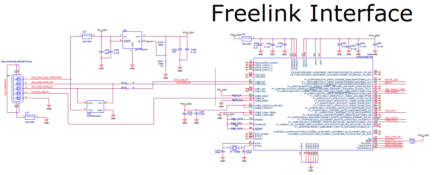
Freelink Interface (Source: NXP i.MX RT1064 Schematics)
The LPC4322JET100 is a ARM Cortex-M4 with a ARM Cortex-M0 coprocessor, both running up to 204 MHz, 512 KByte FLASH and 104 KByte SRAM. Compared to the original OpenSDA with K20DX128 (M4 without FPU, running at 50 MHz) this is a much more powerful processor.
Below is an overview about the most important debug circuit components and jumpers:

Debug Circuit on MIMXRT1064-EVK
Isolation Jumpers
To isolate the onboard circuit and to to use an external debug probe, the jumpers J47 and J48 have to be removed. To completely disconnect the debug circuit, there are J49, J50 and J44 which can be removed too. J45 and J46 are used for the UART connection between the debug interface and the target microcontroller.

Isolation Jumpers (Source: NXP i.MX RT1064 Schematics)
Reset
With Jumper J43 it can be configured if the SW9 directly sends the reset signal to the target MCU or to the debug circuit:

Reset Circuit (Source: NXP i.MX RT1064 Schematics)
DAPLink Firmware
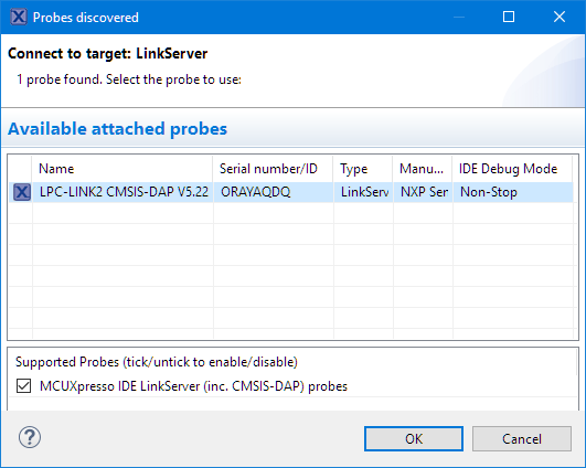
By default the on-board debug circuit shows up as DAPLink CMSIS-DAP device:
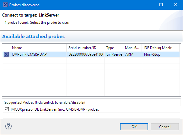
DAPLink CMSIS-DAP
The board comes shipped with the following ‘DAPLink’ firmware:
# DAPLink Firmware - see https://mbed.com/daplink
Unique ID: 02320000070a5e4100000000000000000000000097969905
HIC ID: 97969905
Auto Reset: 0
Automation allowed: 0
Overflow detection: 0
Daplink Mode: Interface
Interface Version: 0246
Bootloader Version: 0244
Git SHA: 475c6729c42c688ae33af3af4ea4dbbfe1c35351
Local Mods: 1
USB Interfaces: MSD, CDC, HID, WebUSB
Bootloader CRC: 0xe493996b
Interface CRC: 0x3eb53105
Remount count: 0
The listed USB MSD is used for drag&drop programming: I could copy a (.bin?) file to the MSD device to program the MCU. To me feature does not have a practical usage: while this could be used as a kind of bootloader, production boards won’t have the OpenSDA circuit on it. Additionally, downloading with the debugger is much faster than using that slow MSD interface, so to me this MSD loader does not make any sense.
More relevant is the USB CDC interface as it provides a ‘UART-2-USB’ connection. And definitely the USB HID interface which is used as debug protocol (so it is not the HID keyboard or mouse, the HID protocol is used by the debugger).
An interesting one is the WebUSB one (https://en.wikipedia.org/wiki/WebUSB). This seems to be a way to securely connect from a web page to the device over USB. I have found an example web page for this https://devanlai.github.io/webdfu/mbed-download/ and seems to be used to use the board with the mbed environment. Sounds like a nice-to-have, or a way to program the board from web based development tools (which don’t make sense for real development anyway). Currently there is a driver for it missing in the Windows Device Manager:
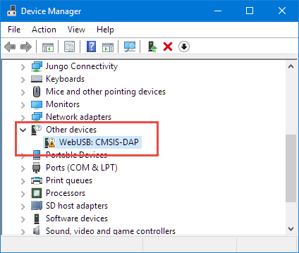
WebUSB in Device Manager
OpenSDA Firmware Files
The good thing with OpenSDA as found on many Freescale/NXP boards is that I can load a different firmware to the debug circuit:
- default CMSIS-DAP firmware (DAP-Link)
- firmware from P&E (acting as a P&E Multilink)
- firmware from SEGGER (acting as a SEGGER J-Link)
Each firmware has its own advantages, and I usually switch the firmware depending on my needs (performance, features). Using the MCUXpresso IDE makes it easy to use any of the different debug probe firmware.
NXP hosts bootloader and firmware files on http://www.nxp.com/opensda. For the other DAPLink/OpenSDA based on Kinetis K20DX128 both P&E (http://www.pemicro.com/opensda/) and SEGGER (https://www.segger.com/downloads/jlink/#JLinkOpenSDABoardSpecificFirmwares) provide firmware files which emulate either a P&E Multilink or SEGGER J-Link on the debug circuit.
💡 At the time of this writing there are no P&E or SEGGER firmware files for the i.MX RT1064 circuit yet.
There is currently no new firmware for the DAPLink available, but if it would be in the future, these are the steps to load a new firmware:
- Power the board with SW09 pressed and hold with a USB cable connected to the debug port:

SW09
- The board should enumerate as MAINTENANCE device:
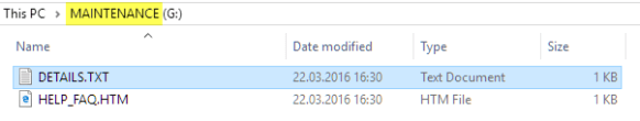
Maintenance Device
- copy the new firmware file to that device.
- Power off and power on the board again, it should have now the new firmware loaded.


Changing the DAPLink into a LPC-Link2
The DAPLink is nice, but slow compared to the LPC-Link2. But most important the DAPLink does not support SWO (Single Wire Output, see “New NXP MCUXpresso IDE V10.3.0 Release“) and SWO trace.
The good news is that with putting a jumper on J42, the MCUXpresso IDE will softload the LPC-Link2 firmware on the LPC4322 and then it will be a LPC-Link2:
- Have the board powered with an external 5V power supply
- Install a jumper on J42

Jumper on J42 to softload LPC-Link2 Firmware
With this, the LPC4322 is running the LPC-Link2 firmware and I can enjoy SWO and 3-4 times faster debugging :-):
NXP i.MX RT1064 Debug Circuit as LPC-Link2
💡 There would be a way to permanently change the firmware using LPCScrypt (https://www.nxp.com/support/developer-resources/software-development-tools/lpc-developer-resources-/lpc-microcontroller-utilities/lpcscrypt-v2.0.0:LPCSCRYPT?&tid=vanLPCSCRYPT). As I did not find a way to reprogram the DAPlink (just in case) using the debug header on the board, I have to wait until the bootloader and DAPLink files coming with the board are available. I will update this post at that time.
Summary
I feel that new debug circuit based on LPC4322 is a big step forward compared to the ‘legacy’ K20 OpenSDA one, and a better match for the higher performance processors. The biggest plus is that I can load a LPC-Link2 firmware. The DAPLink (ARM mbed) firmware is nice, but the LPC-Link2 firmware is much more powerful and really shines in combination with the Eclipse based MCUXpresso IDE.
Happy Linking 🙂
Links
- NXP i.MX RT1064 EVK: https://www.nxp.com/support/developer-resources/run-time-software/i.mx-developer-resources/mimxrt1064-evk-i.mx-rt1064-evaluation-kit:MIMXRT1064-EVK?&tid=vanMIMXRT1064-EVK
- LPC4322JET100: https://www.nxp.com/products/processors-and-microcontrollers/arm-based-processors-and-mcus/lpc-cortex-m-mcus/lpc4300-cortex-m4-m0/high-performance-32-bit-microcontroller-mcu-based-on-arm-cortex-m4-m0-cores:LPC4322JET100
- NXP OpenSDA Files: http://www.nxp.com/opensda
- ARM DAPLink: https://github.com/ARMmbed/DAPLink

“Each firmware has its own advantages, and I usually switch the firmware depending on my needs”
Can you expound further? May make a good post on its own.
LikeLike
That depends to some extend on the used circuit (K20 or LPC4322) of their native probes.
– DAP-Link/CMSIS-DAP:
Pros: open source, usually pre-installed, free of charge, cross-mcu support, need to turn on awareness for FreeRTOS
Cons: rather slow, no SWO, no trace support, requires mbed serial driver, requires expensive Keil tool to build it (at least time I checked it)
– P&E:
Pros: very robust, flash preservation feature, device unlocking feature, SWO and trace (with latest HW), automatic FreeRTOS awareness, live variables, vendor independent
Cons: closed source, no semihosting file I/O (at least last time I checked)
– Segger
Pros: very fast, flash breakpoints, lots of tools and utilities, FreeRTOS awareness (dedicated option), SWO, semihosting file I/O, vendor independent
Cons: closed source, no live variable updates, hard to use with different flash memories (can only have one kind active)
– LPC-Link2/DAPLink
Pros: directly support by NXP, live variables, SWO and trace, decent speed, file I/O semihosting, native support for all NXP ARM Cortex devices
Cons: need to switch between FreeRTOS mode and live variable view
Of course I might have missed a few things, but this should give you an idea
LikeLike
Here is how to update the LPC4322 firmware (the right EVB must be selected). Maybe this helps to restore the LPC as it comes in the EVB box.
https://www.nxp.com/design/microcontrollers-developer-resources/ides-for-kinetis-mcus/opensda-serial-and-debug-adapter:OPENSDA?&tid=vanOpenSDA#MIMXRT1060-EVK
Hope this helps,
Marius
LikeLike
Hi Marius,
this is indeed very useful, thanks for sharing!
Erich
LikeLike
Hi Erich !, I tried change the DAPLink in the i.MX RT1010 Evaluation kit, but I didn’t make it. The MCUXpresso softload it works and the debugger appear as LPC-Link2, however, when I tried to debug an example appears me a lot of errors. The IDE show me a three windows (MCUXpresso IDE: Exception, Problem Ocurred and LinkServer problem).
If the i.MX eval boards share the same debug probe, I don’t have an idea why doesn’t work in RT1010. I followed your instruction step by step.
Regards!
LikeLike
Yes, it should be the same. No idea why it does not work for the RT1010. Unfortunately I don’t own such a RT1010 board, so I cannot verify it.
LikeLike
Thanks for your reply Erich.
I’m using the last version of MCUXpresso, and only I shortcut the J22(that is the same that JP42). I will keep trying.
Changing the subject a bit, I’ve always been curious about how many eval boards do you have… haha xD
LikeLike
I have a few boards, mostly what my students are using and what I’m using for research projects. But the RT EVKs are rather expensive, and my board budget is limited, so that’s why the RT1010 did not make it into the inventory.
LikeLike
The DAPLink in the RT1010 incorrectly identifies itself as the one for the RT1050. You could try the JLINK OB firmware for the probe or override the processor type in some way. I switched to pyOCD and provide “targetId”: “mimxrt1010” to work around the issue
LikeLiked by 1 person
Thanks, that’s really interesting, especially I don’t own a RT1010 board. Where did you see it identifies itself for the RT1050? My understanding is that the Debug firmware on the DAPLink gets all the information from the IDE, so is pretty much ‘MCU agnostic’?
LikeLike
Pingback: Debug Firmware Switching for the LPC4322 | MCU on Eclipse