
I’m using the FRDM-KL25Z in my classes, and that board is very popular: low price (<$15), reasonable features (48 MHz ARM Cortex M0+, 128 KByte of FLASH, 16 KByte of RAM), and many tutorials elsewhere and on McuOnEclipse :-).
For the next (Fall) semester I’m looking for alternative boards, and one is the Freescale (now NXP) FRDM-KL27Z:
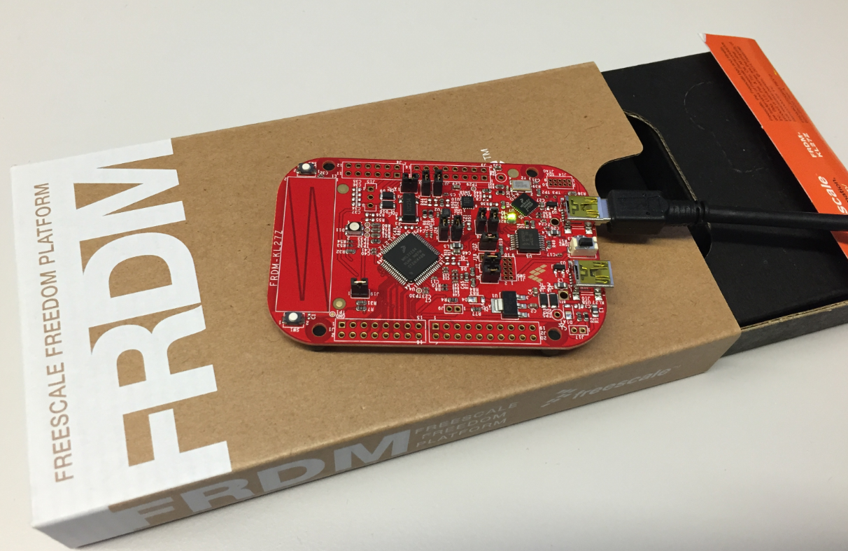
FRDM-KL27Z with Box
FRDM-KL27Z Board
Compared to the KL25Z, the KL27Z board has only half of the flash size (64 KByte instead of 128 KByte), but runs at same frequency (48 MHz ARM Cortex M0+) and has same amount of SRAM (16 KByte). But it does have two push buttons which I miss on the FRDM-KL25Z.
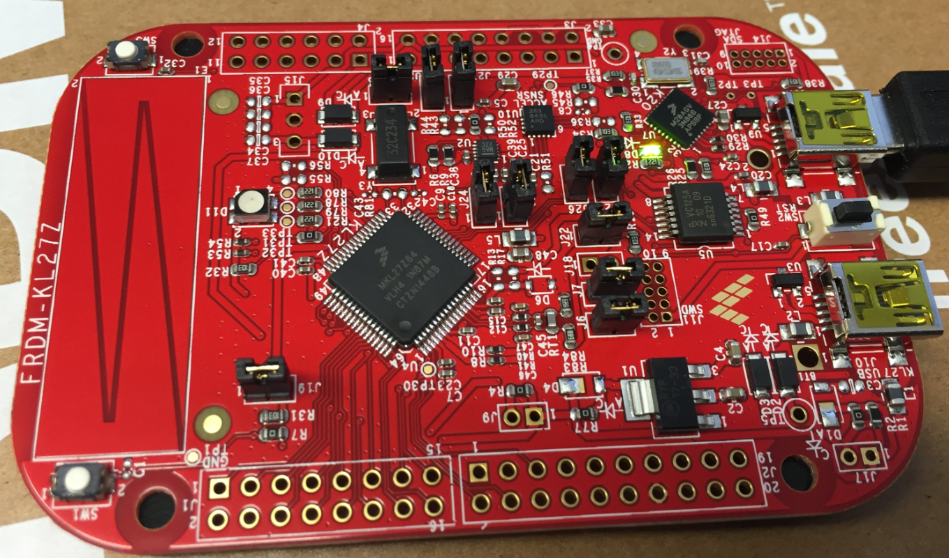
FRDM-KL27Z Board
The FRDM-KL25Z is sold for CHF 14.82 by Farnell, and the FRDM-KL27Z costs CHF 20.07! So this is a big price increase. But I kind of like that board as it comes with the jumpers populated and is one of the newer Kinetis devices with bootloader and crystal-less USB operations.
The KL27Z is supported by the new Kinetis SDK v2, but that SDK does not include Processor Expert :-(. Porting existing KL25Z applications to the KL27Z is easy: one of the main advantages of Processor Expert is that it makes porting from one microcontroller to another one a matter of a few mouse-clicks.
💡 The KL27Z is supported by the Kinetis SDK v1.3 which *does* include SDK Processor Expert components. But these components are incompatible with any previous non-SDK components, and I rather want to be on the latest SDK which is v2.0 now. Porting later things from v1.3 to v2.0 would be time-consuming, as the API between the SDKs are very different (or better to say: completely incompatible). On the plus side, the SDK v2.0 is easier to use, so I want to go with that one and not spending time on the v1.3.
This post is about the usual starting points for embedded projects: blink an LED 🙂 As IDE I’m using Eclipse Luna in Kinetis Design Studio V3.1.0.
Kinetis SDK with Kinetis Expert Portal
See the Freescale community about how to use the Kinetis SDK v2 with Kinetis Design Studio. On kex.nxp.com I have created a new configuration for the FRDM-KL27Z and built the SDK package for the board (see “First NXP Kinetis SDK Release: SDK V2.0 with Online On-Demand Package Builder“):
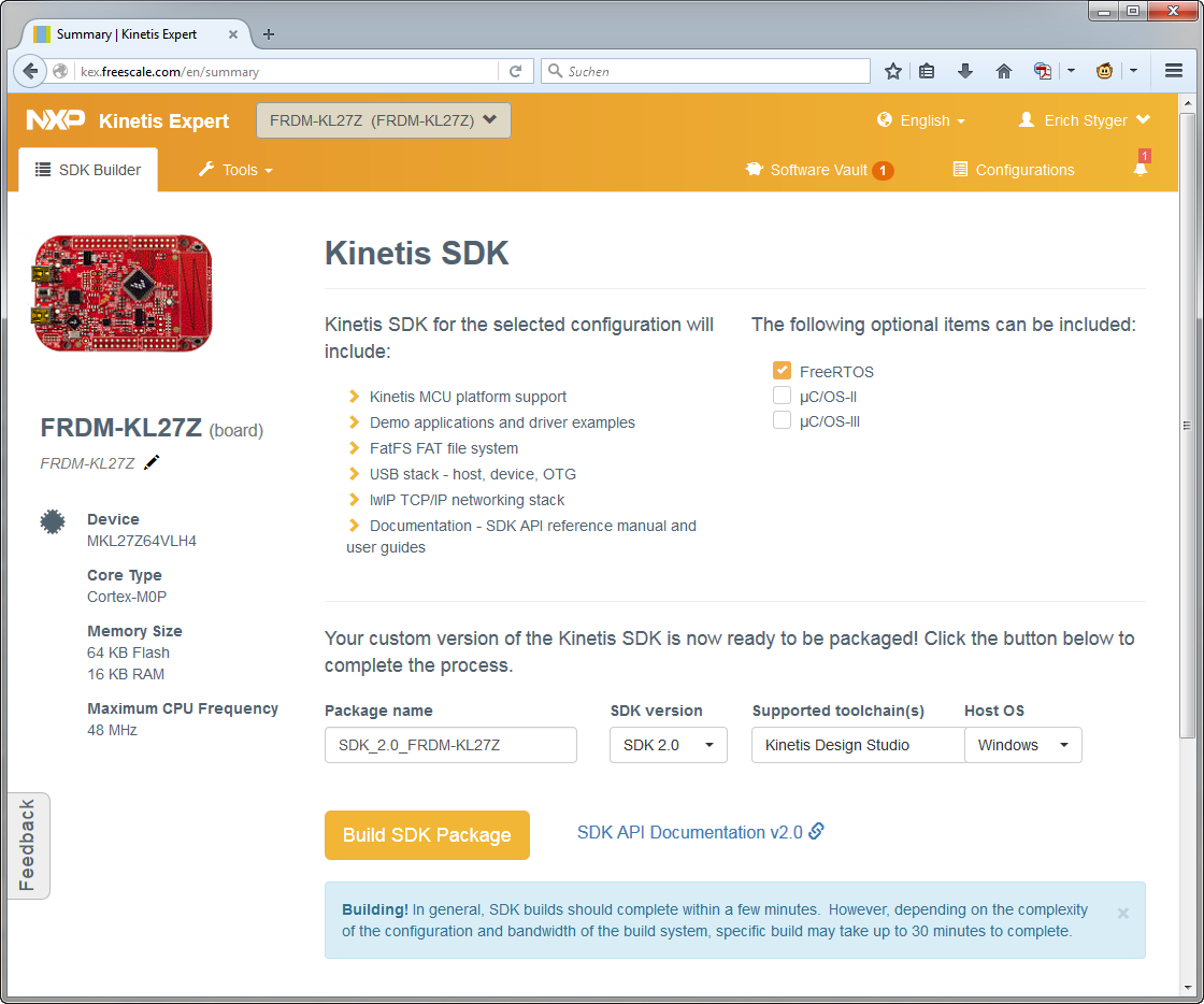
Kinetis SDK for FRDM-KL27Z
I have placed content (unzipped) into the following folder on my disk:
C:\nxp\KSDK\SDK_2.0_FRDM-KL27Z
Project Creating
In Kinetis Design Studio, I use the wizard menu to create a new project:
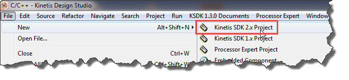
New Project Wizard for the Kinetis SDK v2.0
I have added the location of the SDK and select it for my new project:
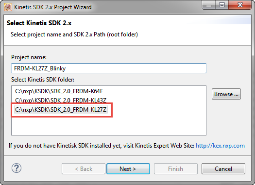
Kinetis SDK Folder
In the next step I select the board with minimal drivers:
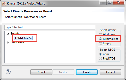
Board Selection
Then finish creating the project. This creates my new blinky project:
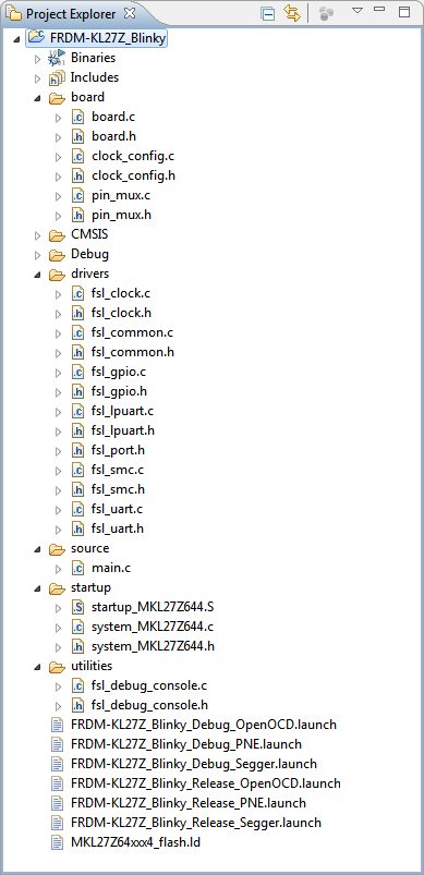
Blinky Project Created
Build and Debug
Click on the Build hammer to build the debug configuration:
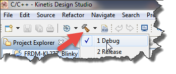
Build
This should build without errors, so I can debug it:
💡 make sure your debug configuration has not the problem described here “Solving “Launching: Configuring GDB Aborting Configuring GDB”“
- Select project
- Press debug button
- Select debug connection
- Press OK

Debug
💡 The FRDM-KL27Z comes with the P&E OpenSDA firmware loaded by default.
With this, I’m successfully debugging the FRDM-KL27Z board the first time 🙂
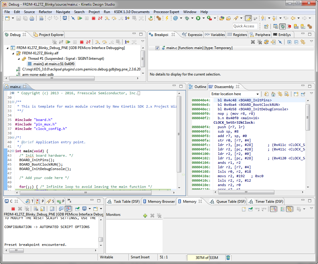
First Debug
Blink!
That project does not do anything, so I have to add the code to blink the LED. Looking at the schematics shows the following pins are used:
- Red: PTB18
- Green: PTB19
- Blue: PTA13
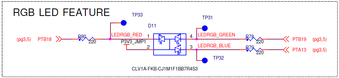
RGB LED Schematic of FRDM-KL27Z (Source: NXP)
So I need to
- Enable the clocks for Port A and B. Without the peripheral clocked, it will not work or even will create a fault when I try to use it.
- Mux the pins. Every pin can be routed (or muxed) to different ports.
- Configure the pins. This configures the pin for the specified operation (e.g. input or output).
Later I can use the pins in the application e.g. to turn the LED on or off.
Init Pins
In main() there is already a call to BOARD_InitPins():
#include "board.h" #include "pin_mux.h" #include "clock_config.h" /*! &nbsp;* @brief Application entry point. &nbsp;*/ int main(void) { &nbsp; /* Init board hardware. */ &nbsp; BOARD_InitPins(); &nbsp; BOARD_BootClockRUN(); &nbsp; BOARD_InitDebugConsole(); &nbsp; /* Add your code here */ &nbsp; for(;;) { /* Infinite loop to avoid leaving the main function */ &nbsp;&nbsp;&nbsp; __asm("NOP"); /* something to use as a breakpoint stop while looping */ &nbsp; } }In the project created this calls the BOARD_InitPins() inside pin_mux.c:
#include "fsl_device_registers.h" #include "fsl_port.h" #include "pin_mux.h" /******************************************************************************* &nbsp;* Code &nbsp;******************************************************************************/ /*! &nbsp;* @brief Initialize all pins used in this example &nbsp;* &nbsp;* @param disablePortClockAfterInit disable port clock after pin &nbsp;* initialization or not. &nbsp;*/ void BOARD_InitPins(void) { &nbsp;&nbsp;&nbsp; /* Initialize LPUART0 pins below */ &nbsp;&nbsp;&nbsp; /* Ungate the port clock */ &nbsp;&nbsp;&nbsp; CLOCK_EnableClock(kCLOCK_PortA); &nbsp;&nbsp;&nbsp; /* Affects PORTA_PCR1 register */ &nbsp;&nbsp;&nbsp; PORT_SetPinMux(PORTA, 1u, kPORT_MuxAlt2); &nbsp;&nbsp;&nbsp; /* Affects PORTA_PCR2 register */ &nbsp;&nbsp;&nbsp; PORT_SetPinMux(PORTA, 2u, kPORT_MuxAlt2); }Currently it does initialize the UART (which I’m not interested in for now). It already enables the clock for port A with
/* Ungate the port clock */ CLOCK_EnableClock(kCLOCK_PortA);Which uses the following interface from fsl_clock.h:
void CLOCK_EnableClock(clock_ip_name_t name);So I add this to enable the clock for port B:
CLOCK_EnableClock(kCLOCK_PortB); /* enable clocks for port B */Next I set the muxing for each pin and set the ‘mux’ for GPIO function. fsl_port.h has the following interface to mux a pin:
void PORT_SetPinMux(PORT_Type *base, uint32_t pin, port_mux_t mux);To mux all three LED pins I use this:
PORT_SetPinMux(PORTA, 13u, kPORT_MuxAsGpio); /* blue led, PTA13 */ PORT_SetPinMux(PORTB, 18u, kPORT_MuxAsGpio); /* red led, PTB18 */ PORT_SetPinMux(PORTB, 19u, kPORT_MuxAsGpio); /* green led, PTB19 */Next, the pins are configured as output pins. For this I need a configuration struct like this:
static const gpio_pin_config_t LED_configOutput = { &nbsp; kGPIO_DigitalOutput,&nbsp; /* use as output pin */ &nbsp; 1,&nbsp; /* initial value */ };The first entry in the struct configures the pin as output pin, and the second entry is the initialization value. As the LEDs are connected with the cathode side to the microcontroller pin, writing a ‘1’ (logical high) will have the LED turned off.
Because that struct and interface is in a header file, I have to include it:
#include "fsl_gpio.h" /* include SDK GPIO interface */The following interface in fsl_gpio.h is used to initialize a pin:
void GPIO_PinInit(GPIO_Type *base, uint32_t pin, const gpio_pin_config_t *config);To initialize all pins I can use:
GPIO_PinInit(GPIOA, 13u, &amp;LED_configOutput); /* mux PTA13 as output */ GPIO_PinInit(GPIOB, 18u, &amp;LED_configOutput); /* mux PTB18 as output */ GPIO_PinInit(GPIOB, 19u, &amp;LED_configOutput); /* mux PTB19 as output */I have highlighted the needed lines for the 3 LEDs below:
#include "fsl_device_registers.h" #include "fsl_port.h" #include "pin_mux.h" #include "fsl_gpio.h" /* include SDK GPIO interface */ static const gpio_pin_config_t LED_configOutput = { &nbsp; kGPIO_DigitalOutput,&nbsp; /* use as output pin */ &nbsp; 1,&nbsp; /* initial value */ }; /******************************************************************************* &nbsp;* Code &nbsp;******************************************************************************/ /*! &nbsp;* @brief Initialize all pins used in this example &nbsp;* &nbsp;* @param disablePortClockAfterInit disable port clock after pin &nbsp;* initialization or not. &nbsp;*/ void BOARD_InitPins(void) { &nbsp;&nbsp;&nbsp; /* Initialize LPUART0 pins below */ &nbsp;&nbsp;&nbsp; /* Ungate the port clock */ &nbsp;&nbsp;&nbsp; CLOCK_EnableClock(kCLOCK_PortA); &nbsp;&nbsp;&nbsp; /* Affects PORTA_PCR1 register */ &nbsp;&nbsp;&nbsp; PORT_SetPinMux(PORTA, 1u, kPORT_MuxAlt2); &nbsp;&nbsp;&nbsp; /* Affects PORTA_PCR2 register */ &nbsp;&nbsp;&nbsp; PORT_SetPinMux(PORTA, 2u, kPORT_MuxAlt2); &nbsp;&nbsp;&nbsp; /* additional clock and configuration for RGB LEDs (PTA13, PTB18 and PTB19) */ &nbsp;&nbsp;&nbsp; CLOCK_EnableClock(kCLOCK_PortB); /* enable clocks for port B */ &nbsp;&nbsp;&nbsp; PORT_SetPinMux(PORTA, 13u, kPORT_MuxAsGpio); /* blue led, PTA13 */ &nbsp;&nbsp;&nbsp; PORT_SetPinMux(PORTB, 18u, kPORT_MuxAsGpio); /* red led, PTB18 */ &nbsp;&nbsp;&nbsp; PORT_SetPinMux(PORTB, 19u, kPORT_MuxAsGpio); /* green led, PTB19 */ &nbsp;&nbsp;&nbsp; GPIO_PinInit(GPIOA, 13u, &amp;LED_configOutput); /* mux PTA13 as output */ &nbsp;&nbsp;&nbsp; GPIO_PinInit(GPIOB, 18u, &amp;LED_configOutput); /* mux PTB18 as output */ &nbsp;&nbsp;&nbsp; GPIO_PinInit(GPIOB, 19u, &amp;LED_configOutput); /* mux PTB19 as output */ }Blinking the LEDs
To blink the LEDs I can use the following API from fsl_gpio.h:
void GPIO_ClearPinsOutput(GPIO_Type *base, uint32_t mask); void GPIO_SetPinsOutput(GPIO_Type *base, uint32_t mask); void GPIO_TogglePinsOutput(GPIO_Type *base, uint32_t mask);With above functions I can put the pin either low, high or toggle it. The first parameter is a pointer to the port, followed by a bitmask for the pin (or multiple pins if they are on the same port).
To slow down the blinking, I add a very simply delay function:
static void delay(volatile uint32_t nof) { &nbsp; while(nof!=0) { &nbsp;&nbsp;&nbsp; __asm("NOP"); &nbsp;&nbsp;&nbsp; nof--; &nbsp; } }💡 I have marked the parameter with ‘volatile’ to prevent compiler optimization, otherwise the compiler generate very fast code for that delay function.
With this, I can add my blinky LED functionality to the main() loop:
int main(void) { &nbsp; /* Init board hardware. */ &nbsp; BOARD_InitPins(); &nbsp; BOARD_BootClockRUN(); &nbsp; BOARD_InitDebugConsole(); &nbsp; /* Add your code here */ &nbsp; for(;;) { &nbsp;&nbsp;&nbsp; GPIO_ClearPinsOutput(GPIOA, 1&lt;&lt;13u); /* blue led on */ &nbsp;&nbsp;&nbsp; delay(1000000); &nbsp;&nbsp;&nbsp; GPIO_SetPinsOutput(GPIOA, 1&lt;&lt;13u); /* blue led off */ &nbsp;&nbsp;&nbsp; delay(1000000); &nbsp;&nbsp;&nbsp; GPIO_ClearPinsOutput(GPIOB, 1&lt;&lt;18u); /* red led on */ &nbsp;&nbsp;&nbsp; delay(1000000); &nbsp;&nbsp;&nbsp; GPIO_SetPinsOutput(GPIOB, 1&lt;&lt;18u); /* red led off */ &nbsp;&nbsp;&nbsp; delay(1000000); &nbsp;&nbsp;&nbsp; GPIO_ClearPinsOutput(GPIOB, 1&lt;&lt;19u); /* green led on */ &nbsp;&nbsp;&nbsp; delay(1000000); &nbsp;&nbsp;&nbsp; GPIO_SetPinsOutput(GPIOB, 1&lt;&lt;19u); /* green led off */ &nbsp;&nbsp;&nbsp; delay(1000000); &nbsp; } &nbsp; for(;;) { /* Infinite loop to avoid leaving the main function */ &nbsp;&nbsp;&nbsp; __asm("NOP"); /* something to use as a breakpoint stop while looping */ &nbsp; } }Running it on the board, and I have a nice ‘blinky’ board application 🙂
Summary
I kind-of like the FRDM-KL27Z board which is supported by the SDK v2. But the SDK v2.0 does not come with Processor Expert which makes porting all the existing projects to the board difficult and time-consuming. And the price of the board is much higher (CHF 20) than the FRDM-KL25Z (CHF 15). I like the two push buttons and the pre-installed jumpers, but that’s a big price add-on with for half of the FLASH memory. And the FRDM-KL25Z is currently better supported by software and tools.
So while I kind a like the board, I’m not sure if I should switch to that board. Students have to pay more if they want to keep the board, they have to learn the new SDK v2 (easier than SDK v1.3, but still more time), and they will be slower and less productive than before with using Processor Expert. With Processor Expert it is a matter of minutes to run a blinky LED application on a brand new board. As someone said: “faster than you can eat a slice of pizza”). Now bigger slices of pizza or needed? Sounds more like to change the type of of lunch? Not sure what will be healthier ;-).
On the bright side, the SDK v2 is much cleaner and easier to use compared to SDK v1.3. Using the SDK v1.3 was not reasonable before, now the SDK v2 could be considered. What I’m thinking about is that there could be some ways to continue using Processor Expert with the SDK v2: to combine the best of two worlds? Maybe worth to explore?
The project created in this tutorial is available on GitHub here.
Happy Blinking 🙂
Links

Brilliant, thanks Eric. I was just sitting down to start playing with my new KL27Z and your blog post appeared at the same time 🙂
It is a shame they (NXP) have dropped Processor Expert. I wonder why they made that decision…
LikeLike
Hi Geoff,
ah, good timing then :-).
LikeLike
While I liked my FRDM KL25Z board, I’ve moved my applied electronics class to the Teensy LC board. It is an even cheaper board that can be easily plugged into a breadboard, and the Teensyduino development system, while much less featureful than the Kinteis SDK is much easier to use. (I wasn’t using Kinetis SDK with the FRMD KL25Z board, but MBED.ORG, which was rather irritating to use as a web-only application with a crummy and slow interface.)
LikeLike
Yes, I looked at the Teensy and Teensy LC. I have used the Teensy in a few projects, but the fact that you cannot debug it (there is no SWD/JTAG header) removes it from the list for future projects. I don’t like if development tools like Teensyduino have to be used. For your classes things are probably different, but in my classes students need to learn real tools (and not things like mbed or Teensyduino): they need to be able to develop safety critical applications and printf() style debuggging won’t help or will be catastrophic in my view.
I like the Teensy because they are bread board friendly, but again, you cannot debug it. That’s why we came up with the tinyK20 board (https://mcuoneclipse.com/category/boards/tinyk20/) which solves that problem.
The Kinetis SDK v2 got better now compared to the V1.x, so I’ll give it a try over the next months to explore it more.
LikeLike
What if there where a series of low cost boards available for Kinetis that had no on board Jtag converter or other superfluous add-ons such as accelerometers & RGB leds. One only needs to purchase a J-Tag adapter or two for around $60US each. If such boards could fit into a breadboard as your TinyK20 board does perhaps that would be the way to go. Perhaps these boards could be produced for $5 to $7US each depending on the MCU fitted. If Texas Instruments can sell MSP432 boards for $4.32US there is a challenge for NXP …
LikeLike
Hi Chad,
yes, I agree with you: the extra components (which might not be used at all) adds up to the board costs and especially board size (which increases costs too).
Having the debug adapter separate is the way to go for me, and as a low cost option it does not have to be expensive: NXP has the LPCLink (http://www.mouser.ch/ProductDetail/NXP-Semiconductors/OM13054UL/?qs=sGAEpiMZZMvcRsgoMFfeP3LpSOTCZIep30zvo6bRrI0%3d) which is sold for CHF 20, and in my view that one could be simplified and less expensive too. I’m ok to have very low cost run control device like this, I still want to have a good solid run control device like a Segger or P&E because they are usually faster and can do difficult jobs better.
As for the price point you mention: I think it is all about volume. And to me, there are too many Freedom boards so there is not enough volume for each. Maybe with the exception of the FRDM-KL25Z as this one is very popular, and it is one of the least expensive (best bang for the buck). They could shrink the package (needs less space in the warehouse, easier to ship). But what I think adds to the costs that they are sold through Farnell/Mouser/etc: they must have some marging too. If that $4.32US matches the real costs or if this cost is reduced with some marketing money, I don’t know. Compared to the $5US for a Raspberry Pi Zero (https://mcuoneclipse.com/2015/11/28/a-raspberry-pi-for-5-what-are-your-decision-factors/) (which does not cover the costs I believe) I think there might not be much cost reality in the market? I’m ok to pay a valid price for a board, if the features match my needs, and if I can use it with my software and tools.
LikeLike
Hi Erich,
It is good to see a simple example like this (or extremely complicated depending on your point of view) for KSDK2.0.
How can anyone in NXP think that this is progress compared to using Processor Expert. Do any of the decision makers have a grasp of this?
It truly would be fantastic to have PE and KSDK 2.0 working together. For the time being I am using PE and 1.3 reasonably successfully, but know that I will need to move on at some point.
Best Regards
Jim
LikeLike
Hi Jim,
“have PE and KSDK 2.0 working together”: what I’m considering are some ways how I could transfer my work with the components to the SDK v2 world. I have done some experiments over the week-end, and it is promising: I can use things like LED, GenericI2C, Wait, Utility, GenericBitIO and other components now with the SDK v2. However, this only applies to the McuOnEclipse components, and is more about re-using the IP/Sources with the SDK. It won’t solve the problem that there is no CPU component with the SDK which would know everything about the hardware. I belive there is no workaround for this. But at least I could continue to use all the drivers and software, and possibly migrate easier to the ‘new world’.
Erich
LikeLike
Opinions:
I feel like with the merger between NXP and Freescale, the “New NXP” hasn’t spent the time on the education and hobbyist market at the moment. Once all the fundamentals with sdk’s, board, and chip designs are all worked out to strengthen other market shares, then they will come back to a different version of Processor Expert.
I assuming KDS will merge with LPCXpresso, or one will get phased out, and KSDK2.0 is just a transition phase for older freescale chips and boards to easily transfer to the next IDE.
LikeLike
Excellent, thanks Eric.
Using your blog + PE knowledge I implemented this RGB_toggling on K64F.
What will happen with all PE goodies like complex peripherals support or “Component Library “ (like LCD component)?
Each individual will have to develop it by himself for each platform?
All new MCU /SOC’s specs are covered by hundred/thousand page manuals, tool like Processor Expert is must.
Processor Expert was one of the Freescale advantages. In my opinion aborting Processor Expert without providing any alternative will be NXP strategic mistake.
Thanks again for your helpful and excellent blogs as a beginner I use them a lot.
LikeLike
Hi Shaul,
Thanks for your feedback, appreciated 🙂
That’s exactly the reason why the students any myself like Processor Expert: it basically saves me a lot of time reading all the referencen manuals. Up to the point that the reference manuals are not clear or even wrong, but I get working code out of Processor Expert. As for the components: All what I try with experiments now is how to get my components (LCD, RNet, BitIO, etc) moved over to the SDK world. You might see where I am at with looking at my most recent GitHub commits here: https://github.com/ErichStyger/McuOnEclipse_PEx
It is still a long way to go, and I still need to come up with a good article about this. But at least for some code it seems there is away to get Processor Expert (at least some of it) with the Kinetis SDK.
LikeLike
Hi Erich,
This is a nice article on KL25 and KL27 FRDM boards and the features development tools offer to support them.
I’d say KL27 can be of interest if one wants to explore the FlexIO IP and use it to come up with a solution when other (i.e. standard) peripherals are either inefficient or simply cannot perform the given task at all.
The KL27 reference manual provides basic examples on how to configure the FlexIO as a UART, SPI, I2C, etc. However, the FlexIO can do much more than that. I had a lot of fun exploring this IP using a KL27 FRDM board and building several applications supporting unique serial protocols and really strict timing requirements when handling external signals.
Regards,
Zeljko
LikeLike
Hi Zeljko,
yes, the FlexIO thing is very interesting, and it does exist on other FRDM boards too. But the the FRDM-KL43Z is more attractive in my view?
LikeLike
On the KL27 the I2C hardware is broken as explained in freescale community.
Repeated Start does not work correctly. Freescale/NXP has yet to issue a proper errata about the problem or better yet fix the parts.
Do you have any suggestions for a work around besides switching to bit-banging or FlexIO (which require a hardware change because they are on different pins)?
LikeLike
Hi Bob,
I have not used I2C on these new parts (yet?), so I might not be the best person to answer your question. But I was running into another nasty I2C bug with the KL25Z which exists on many other Kinetis devices (https://mcuoneclipse.com/2012/12/05/kl25z-and-i2c-missing-repeated-start-condition/). So not sure if this is related to the same thing? Maybe the same workaround (not using clock devider) solves the problem on the KL27 too?
LikeLike
Alas it is yet an other new I2C problem, that is unique to the KL27 family.
I2C seems simple yet no manufacture every seems to get it correct. 😦
LikeLike
yes, and even worse: because the silicon designers are copy-pasting their IP from one design to another, they distribute the silicon bugs like a virus to all other devices 😦
LikeLike
I don’t think the KL27 I2C is broken, it just works differently due to double buffering. In polled mode, I have repeated start working by checking the EMPTY flag in the S2 register after setting RSTA in the C1 register. I haven’t yet checked how this would work in interrupt mode.
As usual with I2C, it’s best to read, re-read and sill re-re-read the user manuals, this applies to all MCUs I’ve worked with so far…
LikeLike
Pingback: Tutorial: Using Eclipse with NXP MCUXpresso SDK v2 and Processor Expert | MCU on Eclipse
Thank you so much”!!
Your post make me see how things work with kinetis and their SDKs. After two days of trying to make my KL25z work with MCUXpresso, Finally I was able of make the Red Led to blink.
Cheers from México!.
LikeLike
Hi Daniel,
yes, I know myself that getting started with the SDK is not simple and easy. Glad to hear that this article was helpful for you!
Cheers from Switzerland!
LikeLike
Pingback: Black Magic Open Source Debug Probe for ARM with Eclipse and GDB | MCU on Eclipse