
The bad news: my ESC (see “Kinetis Drone: Graupner ESC S3055 Failure“) for my Kinetis drone is still not repaired :-(. Anyway, I have plenty of other things to make for my drone project. One is to work on the remote controller:
Test Setup
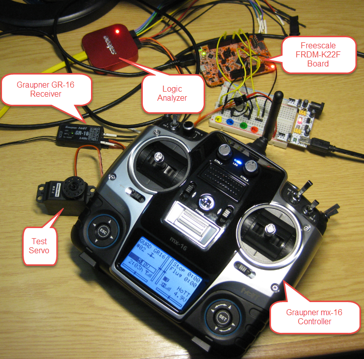
I have Bluetooth and a Nordic nRF24L01+ transceiver connected with the FRDM-22F board which provides me good short distance connectivity with Bluetooth around 10 m and nRF24L01+ in the 50-100 m range. For outdoor usage I need something for the 200-300 m range. Therefore I organized a Graupner mx-16 controller: a 8 channel remote controller, perfect for flying a quadrocopter:
The mx-16 came bundled with the Graupner GR-16 receiver:
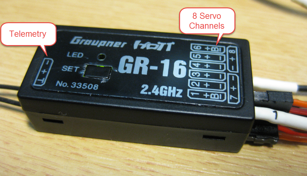
Graupner GR-16
The GR-16 has one telemetry/programming port and can drive up to 8 servo channels. So it would be possible to connect directly the 4 ESC’s of the quadrocopter to the four first channels, but then I would not have any gyro stabilization. Instead, I want the Freescale FRDM-K22F read the servo signals and drive the ESC’s with the Kinetis K22F with the help of the sensors.
So I would like to use a ‘standard’ remote controller with a ‘standard’ receiver, but read the receiver signal with a microcontroller and drive the motors with the microcontroller.
Servo Signals
The output signals of the transceiver is a normal servo signal: 50 Hz with a duty of 1-2 ms:
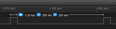
Typical Servo Signal
But 50 Hz is rather slow for a dynamic system like a quadrocopter. Additionally it would mean that I need to sample/read at least four such signals which would be doable, but painful.
SUMD Protocol
Flight controllers need a better way of getting input signals, and for this several analog and signal bus system exist, for example Futaba SBUS or the Graupner SUMD.
Instead of sending a PWM value with 50 Hz, the SUMD protocol is a digital signal and sends multiple channels with 100 Hz (every 10 ms). The logic analyzer capture shows two 8 channel data packets:
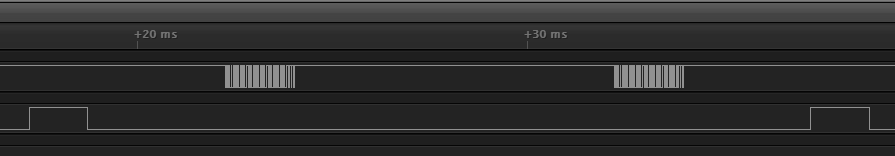
SUMD Data Frames
The really cool thing with SUMD is that it is a normal UART/Serial protocol: 8N1, 115200 baud 🙂
SUMD Data Packet
The data has a header, followed by the data and a checksum. For the above frame here is what the values mean:
- 0xA8: Header identification for Graupner
- 0x01 or 0x81: Identification for a data frame with transmitter in fail safe (0x81) or normal (0x01) condition
- 0x08: Number of channels, with 16bit data each
- 0x2EE0….0x2EE0: data packets
- 0xF90F: CRC Checksum
💡 I would have expected that 0x81 is sent when the receive is in safe mode (see later below). But in my findings the 0x81 is only sent if the transceiver is powered up with no receiver signal present. Otherwise it sends 0x01 even if he lost the radio signal. This does not make sense to me?
The data packets are between 0x1c20 (-150%, 900 μs, extended low position) up to 0x41a0 (+150%, 2100 μs) for extended high position.
Voltage Level
The receiver is powered with 5V DC, but I have not found any documentation about the voltage level of the output signals. To my surprise the SUMD signal is a 3V one, so no need to use a level converter to use it with a 3.3V microcontroller :-):
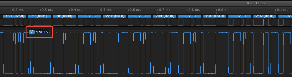
SUMD Voltage Level
SUMD Signal Configuration
The receiver needs to be configured to produce a SUMD signal. The signal is always emitted on servo port number 8. The setting is hidden in the Telemetry settings:
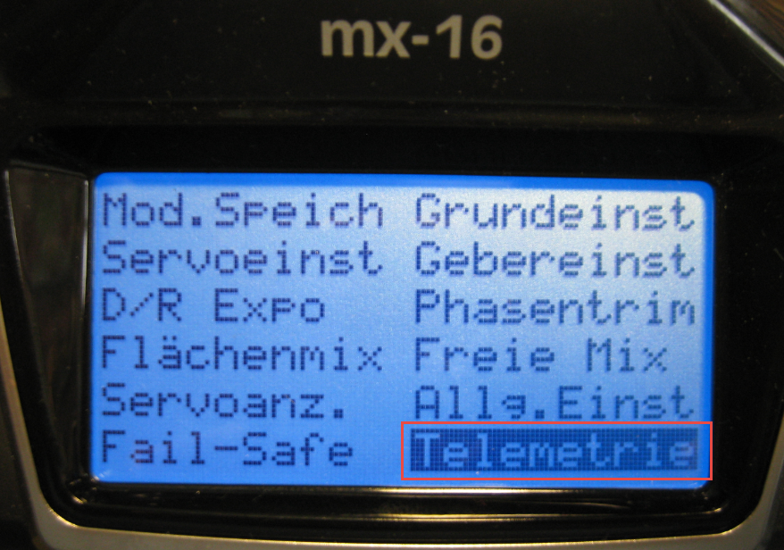
Telemetry Menu on mx-16
Then select the Settings menu:
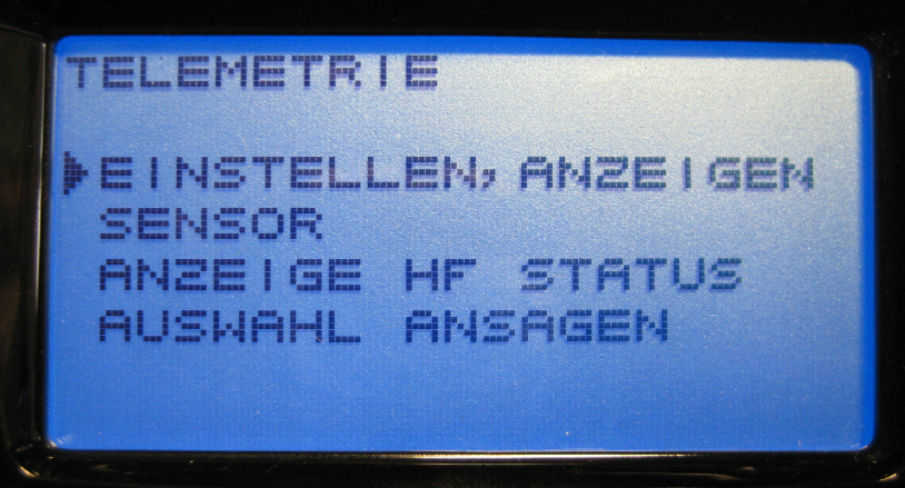
Telemetry Settings Menu
The setting I’m looking for is under the “RX Servo” page, behind “CH OUT TYPE” which is by default ‘ONCE’ for the GR-16:
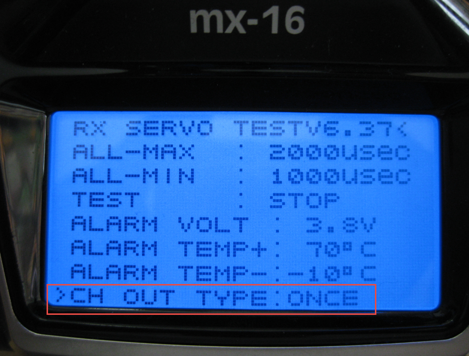
CH OUT TYPE (default)
The following types are supported by my receiver firmware (Information from http://www.graupner.de/mediaroot/files/33700_SMART_BOX_WEB_GB.pdf):
- ONCE: the receiver outputs are transmitted in sequence: recommended for analogue servos. This setting ensures that the servos are automatically operated using a 20 msec cycle – 30 msec in the case of the twelve-channel receiver (Order No. 33512) – regardless of the value set and displayed in the RX SERVO display under the menu point ‘PERIOD’.
- SAME: the receiver outputs are transmitted in parallel blocks of four, i.e. channels 1 to 4 and channels 5 to 8 receive the transmitter signal simultaneously in each case: recommended for digital servos. It is particularly useful where multiple servos are used for a particular function (e.g. ailerons), so that all the servos move absolutely synchronously. It is also possible to connect analogue servos; in this case you
must set 20 ms in the menu point ‘PERIOD’ in the RX SERVO display. Note: if you select the SAME setting, it is especially important to install a high-capacity receiver power supply system, as up to four servos are almost always working simultaneously, placing a greater load on the battery. - SUMI: (Sum signal Input): Input for satellite receiver. With that mode it is possible to have a ‘satellite’ receiver for redundancy, see http://fluggeil.de/articles.php?article_id=116 (in German).
- SUMD: (Sum digital out) Produces a digital sum signal which can be read in e.g. by a microcontroller. The sum signal has all the servo signals in one data packet, so I only need to read that signal. The SUMD signal is always issued on servo channel 8 on the GR-16, and that channel might be different for each receiver.
In SUMD mode, I can configure a failsafe type and the number of channels. With the failsafe mode I can specify what shall happen in case the receiver does not receive a signal.
- SUMD OF (Failsafe OFF): No signal is emitted in case of communication loss.
- SUMD FS (Failsafe POSITION): In case of communication loss, the preconfigured failsafe servo positions are sent. For example I can configure ‘safe’ servo settings and if the receiver goes out of range, it will default to the safe settings.
- SUMD HD (Failsafe HOLD): In this mode, the receiver will continue to emit the last received values.
I have configured it for SUMD-FS-08 (SUMD, Failsafe Position with 8 channels):
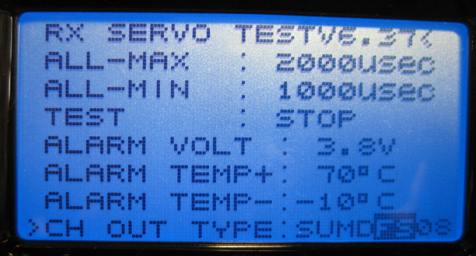
SUMD Configuration
The SUMD Signal is always on Servo Connector/Channel 8 of the GR-16:
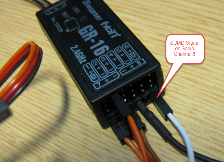
SUMD Signal on Channel 8
SUMD Decoder
The SUMD decoder I’m using is taken from the PX4 PixHawk Autopilot project (https://pixhawk.ethz.ch/docs/sumd_8c.html).
💡 The original PX4 SUMD implementation did not handle the 0x81 failsafe byte. I have extended the implementation to cover this case.
SUMD Rx Input
I have configured the UART (AsynchroSerial) component to read the SUMD data. As it is Rx only, I do not need the Tx pin. I have configured it to use UART2 with Rx on PTD2 and 115200 baud. Additionally I have enabled UART interrupts with an internal buffer of 128 bytes (less would do it too):
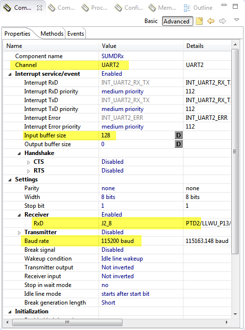
SUMD Rx Pin Configuration
The picture below shows the wiring with SUMD to UART2/PTD2:
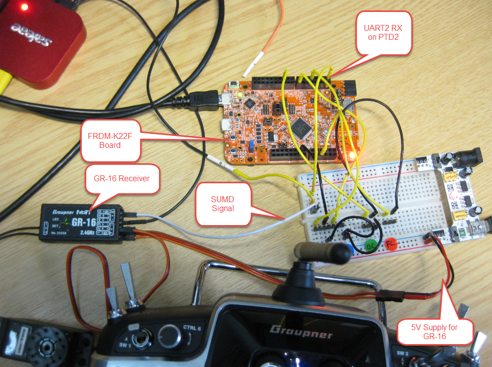
SUMD Wiring
If using the Bluetooth module, then UART0 with RxD on PTD6 can be used:
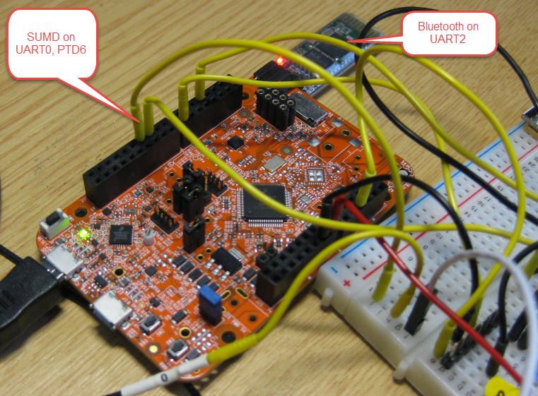
SUMD with Bluetooth Combined
Remote Module
To read in the SUMD signals, I have created a ‘Remote’ module. It runs a FreeRTOS task to read in the data from the UART. I have a shell interface added so I can inspect the received channel data:
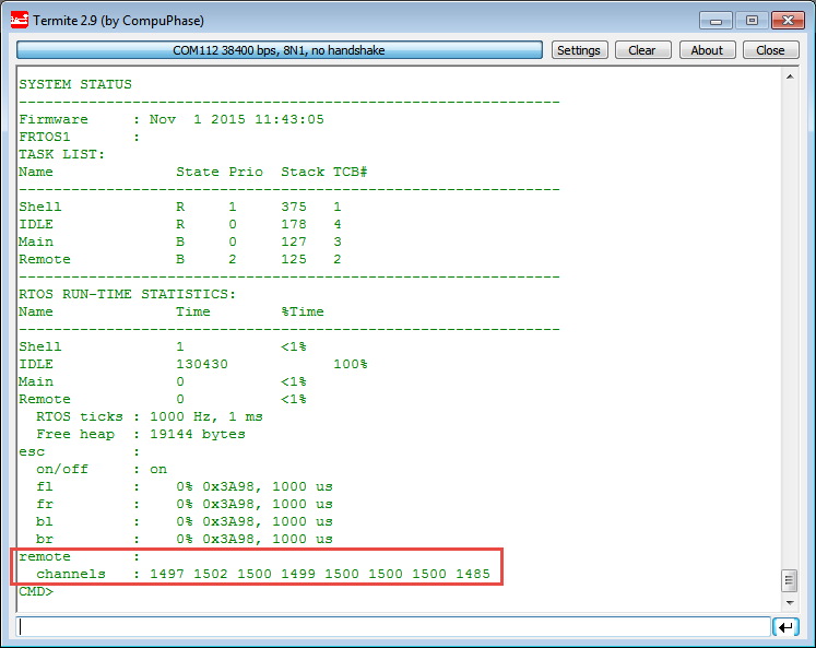
Remote Channel Status
/*
 * Remote.c
 *
 * Created on: 31.10.2015
 * Author: Erich Styger
 */

#include "Platform.h"
#if PL_HAS_REMOTE
#include
#include "Remote.h"
#include "FRTOS1.h"
#include "SUMDRx.h"
#include "UTIL1.h"
#if PL_HAS_SUMD
 #include "SUMD.h"
#endif
#if PL_HAS_SHELL
 #include "Shell.h"
#endif

static uint16_t REMOTE_channels[SUMD_MAX_CHANNELS];

#if PL_HAS_SUMD
const uint8_t testSUMD[] = /* test message */
{
 0xA8, /* Graupner ID, start */
 0x01, /* SUMH/SUMD */
 0x08, /* number of channels */
 0x2E, 0xE8, /* data channel 1 */
 0x2E, 0xD0, /* data channel 2 */
 0x2E, 0xF0, /* data channel 3 */
 0x2E, 0xe0, /* data channel 4 */
 0x2E, 0xE0, /* data channel 5 */
 0x2E, 0xE0, /* data channel 6 */
 0x2E, 0xE0, /* data channel 6 */
 0x2E, 0xE0, /* data channel 8 */
 0x57, 0xB4, /* CRC */
};

static uint8_t ReadSUMD(void) {
 int res;
 int i;
 uint8_t rssi=0; /* Received Signal Strength Indicator, not used as SUMD does not provide this */
 uint8_t rx_count=0; /* counter of received packets, will be incremented for each received packet */
 uint16_t channel_count; /* number of received channels in data packet */
 uint16_t channels[SUMD_MAX_CHANNELS]; /* here the channel data get stored */
 uint8_t ch;

 res = 1; /* preset to accumulating */
 while(res==1){
   if (SUMDRx_RecvChar(&ch)==ERR_RXEMPTY) {
     break;
   }
   res = sumd_decode(ch, &rssi, &rx_count, &channel_count, &channels[0], sizeof(channels)/sizeof(channels[0]));
   /* @return 0 for success (a decoded packet), 1 for no packet yet (accumulating), 2 for unknown packet, 3 for out of sync, 4 for checksum error */
 }
 if (res!=0) {
   return ERR_FAILED;
 }
 /* copy data */
 FRTOS1_taskENTER_CRITICAL();
 memcpy(REMOTE_channels, channels, sizeof(REMOTE_channels));
 FRTOS1_taskEXIT_CRITICAL();
 return ERR_OK;
}
#endif

static void Remote(void *pvParameters) {
 (void)pvParameters; /* parameter not used */
 uint8_t res;

 for(;;) {
 #if PL_HAS_SUMD
   res = ReadSUMD();
 #endif
   FRTOS1_vTaskDelay(10/portTICK_RATE_MS);
 }
}

#if PL_HAS_SHELL
static void REMOTE_PrintHelp(const CLS1_StdIOType *io) {
 CLS1_SendHelpStr((unsigned char*)"remote", (unsigned char*)"Group of remote commands\r\n", io->stdOut);
 CLS1_SendHelpStr((unsigned char*)" help|status", (unsigned char*)"Shows remote help or status\r\n", io->stdOut);
}

static void REMOTE_PrintStatus(const CLS1_StdIOType *io) {
 int i;
 uint8_t buf[32];

 CLS1_SendStatusStr((unsigned char*)"remote", (unsigned char*)"\r\n", io->stdOut);

 CLS1_SendStatusStr((unsigned char*)" channels", "", io->stdOut);
 for(i=0;i<sizeof(remote_channels) sizeof(remote_channels[0]);i++)="" {="" cls1_sendnum16u(remote_channels[i],="" io-="">stdOut);
   CLS1_SendStr(" ", io->stdOut);
 }
 CLS1_SendStr("\r\n", io->stdOut);
}

uint8_t REMOTE_ParseCommand(const unsigned char *cmd, bool *handled, const CLS1_StdIOType *io) {
 uint8_t res = ERR_OK;
 int32_t val;
 const unsigned char *p;

 if (UTIL1_strcmp((char*)cmd, (char*)CLS1_CMD_HELP)==0 || UTIL1_strcmp((char*)cmd, (char*)"remote help")==0) {
   REMOTE_PrintHelp(io);
   *handled = TRUE;
 } else if (UTIL1_strcmp((char*)cmd, (char*)CLS1_CMD_STATUS)==0 || UTIL1_strcmp((char*)cmd, (char*)"remote status")==0) {
   REMOTE_PrintStatus(io);
   *handled = TRUE;
 }
 return res;
}
#endif /* PL_HAS_SHELL */


void REMOTE_Init(void) {
 if (FRTOS1_xTaskCreate(
   Remote, /* pointer to the task */
   "Remote", /* task name for kernel awareness debugging */
   configMINIMAL_STACK_SIZE, /* task stack size */
   (void*)NULL, /* optional task startup argument */
   tskIDLE_PRIORITY+2, /* initial priority */
   (xTaskHandle*)NULL /* optional task handle to create */
   ) != pdPASS)
  {
     for(;;){} /* error! probably out of memory */
  }
}
#endif /* PL_HAS_REMOTE */
First Test Runs
And here is my rough test setup: The quadrocopter (FRDM-K22F board, motors and receiver) is powered by the battery. The remote controller is used to affect the speed of the motor(s).
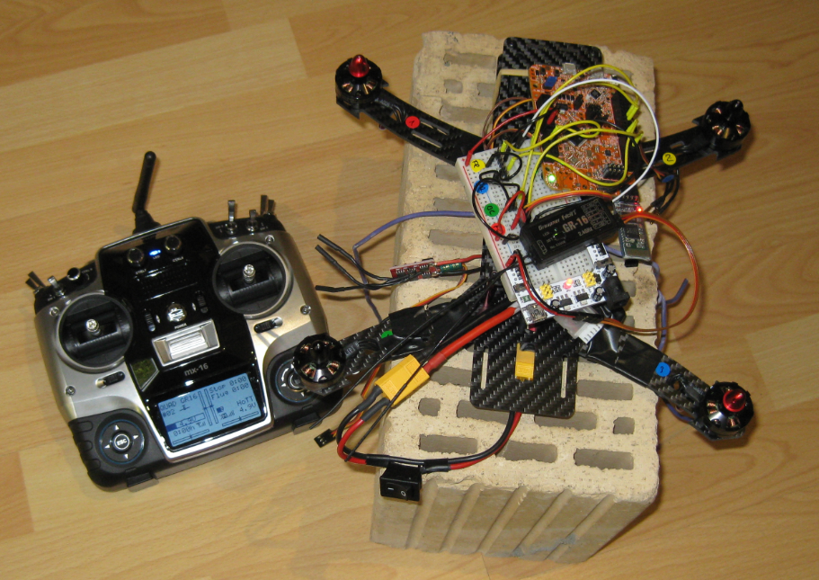
Kinetis Drone Test Setup with Graupner mx-16
For safety reasons only one motor only, and the quadrocopter tied to the ground :-):
- Turning on power supply for the copter
- Turning on remote controller and enable radio
- Moving the stick to affect the motor
Summary
I have now the ability to use a normal RC control unit with a receiver to send signals to the microcontroller. Using the SUMD signal I can use a UART to read in the sum signal and then process it be the microcontroller. That way I have a handy way either to control my quadrocopter, or any robot or any kind of things for which I want to have a remote controller :-).
One of the next steps will be to cleanup the hardware wiring and use the sensors to help my flying this beast ;-). And yes, I need to have that ESC repaired too…
Happy Remoting 🙂
Links:
- Kinetis Drone project on GitHub: https://github.com/ErichStyger/mcuoneclipse/tree/master/Examples/KDS/FRDM-K22F/FRDM-K22F_Drone
- Used Processor Expert components: McuOnEclipse Releases on SourceForge
- Graupner mx-16 controller: http://www.graupner.de/en/products/1d80881f-8353-4c86-8a6d-2ebefc64e1c1/33116/product.aspx
- Graupner GR-16 receiver: http://www.graupner.de/en/products/d3601541-a7a0-4f5f-8f0a-a624d262d28f/33508/product.aspx
- RC Radio Types: http://blog.oscarliang.net/pwm-ppm-sbus-dsm2-dsmx-sumd-difference/
- Graupner SUMD Data Protocol: http://www.deviationtx.com/media/kunena/attachments/98/HoTT-SUMD-Spec-REV01-12062012-pdf.pdf
- PX4 PixHawk autopilot project: https://pixhawk.ethz.ch/, https://pixhawk.org/start
- Assembling the Quadrocopter frame: “Kinetis Drone: Frame Construction with Graupner Race Copter Alpha 250 Q“
- Driving the ESC’s: Kinetis Drone: Driving the Electronic Speed Controllers
- Sensor Fusion: Kinetis Drone: Sensor Fusion Toolbox
- Failure point of ESCs: Kinetis Drone: Graupner ESC S3055 Failure

Drones are one of the hottest items of the year. You see them getting into trouble on the news, getting Cartman into trouble on South Park, but most importantly, you’ve been seeing a lot of stunning videos and photos captured by a drone. Drones have piqued the imagination of creatives all over the world, making aerial photography and videography more cost effective than ever. And if you’re reading this, there’s a good chance you want to get your feet wet as well.
LikeLike
Pingback: Kinetis Drone: First Test Flights | MCU on Eclipse