In “Kinetis Drone: Frame Construction with Graupner Race Copter Alpha 250 Q” I have assembled the frame for my Kinetis Drone. In this post I’m going to drive the ESC’s (Electronic Speed Controllers) with the Freescale FRDM-K22F board:
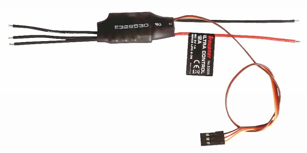
Graupner S3055 ESC (Source: Graupner)
Electronic Speed Controller (ESC)
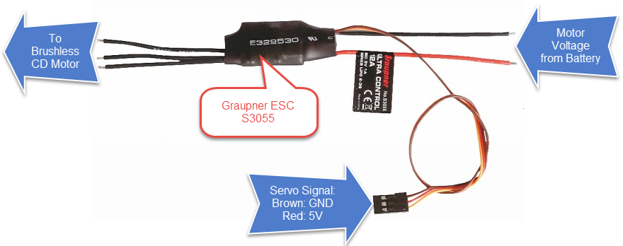
The Graupler Race Copter Alpha 250 kit included 4 Electronic Speed Controllers (ESC’s) of type S3055 (http://shop.graupner.de/webuerp/AI?ARTN=S3055). Basically a ESC is small microcontroller board which takes a PWM signal and drives a brushless DC motor:
From the S3055 data sheet I have this data:
- Voltage: 2-4S LiPo (nominal 7.4-14.8V)
- Dimensions: 25x20x7 mm
- Weight: 9 Gramm
- Max current: 12A
- BEC output: 1A/5V
Battery Elimination Circuit
BEC stands for ‘Battery Elimination Circuit’: basically it means that the ESC can provide me a 5V power with up to 1A from the battery voltage. That way I can power things like the FRDM board on the quadrocopter with that 5V and do not need a dedicated power supply or battery :-). The 5V is provided to the red (5V) cable of the Servo cable. Later I will use that 5V to power the FRDM-K22F board.
Servo PWM
Typically each four of the Servo connectors would be connected to a remote servo receiver like the GR-18 which has up to 8 servo connectors:

Graupner GR-18 Receiver (Source: Graupner)
Such a receiver gets the remote controller signal and then sends the PWM signal to the ESC’s. I plan to use such a receiver and use the SUMD (combined digital signal of the servo) to be feed into the FRDM-K22F. That way the FRDM can receive signal from a normal remote controller (beside of Bluetooth and nRF24L01+). I plan to use the Bluetooth and nRF24L01+ for diagnostic data and to drive the Quadrocopter inhouse. But for larger distances and outside I plan to use a normal remote controller.
PWM’ing the ESC’s
Unfortunately the ESC data sheet did not tell what kind of PWM signal :-(. After some research I have found that it takes a normal ‘Servo’ signal (see https://en.wikipedia.org/wiki/Servo_control):
- Signal Frequency: 50 Hz (20 ms period)
- Pulse width (active high) somewhat between 1000 μs (zero throttle) and 2000 μs (full throttle)
It seems that signal frequency has to be at least 50 Hz, but most ESC’s allow a higher frequency up to something between 300 and 400 Hz (see http://aeroquad.com/showthread.php?5502-Which-PWM-frequency-do-I-use-to-control-my-ESC). Unfortunately I have not found any data in the Graupner data sheet 😦
ESC Calibration and Initialization
The pulse width minimum and maxium value can be configured with a calibration routine (see http://robots.dacloughb.com/project-2/esc-calibration-programming/). For the quadrocopter I would like to use a range as big as possible between LOW and HIGH.
To calibrate the ESC (S3055, but similar for other ESC’s):
- Send a PWM signal for ‘max throttle’ to the ESC (say 2000 μs PWM duty).
- Power the ESC from the battery.
- The ESC beeps twice to show that he detected the signal. The ESC stores this as ‘maximum position’.
- Now within at least 2 seconds, send a PWM signal for the low signal (say 1000 μs PWM duty).
- The ESC peeps for a long time to show that low position is recognized and stored.
To normally initialize the ESC’s:
- Power up the ESC with a PWM signal for ‘min throttle’ to the ESC (say 1000 μs PWM duty).
- The ESC beeps once to show that he detected the signal.
- Now within at least 2 seconds, send a PWM signal for the low signal (say 1000 μs PWM duty).
- The ESC peeps for a long time to show that low position is recognized and stored.
- The ESC beeps to show the number of cells (voltate), e.g. 4 times for 14.8V
- The ESC beeps a ‘1-2-3’ signal and is ready
The following graph shows the sequence for a calibration (left side) and the normal initialization (right side) with the audio recording:
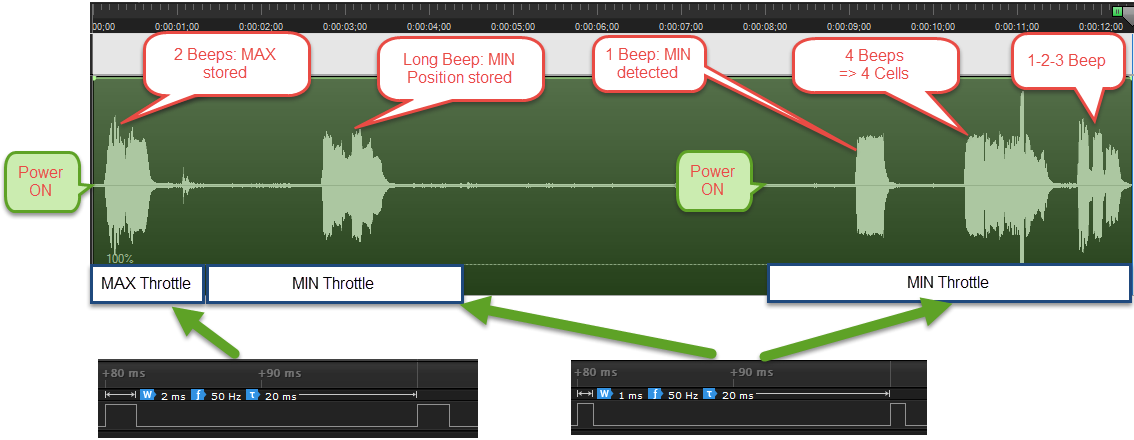
ESC Calibration and Init
With this I have been able to calibrate and initialize the motors. I have now connected the 4 ESC’s to the FRDM-K22F with a small breadboard:
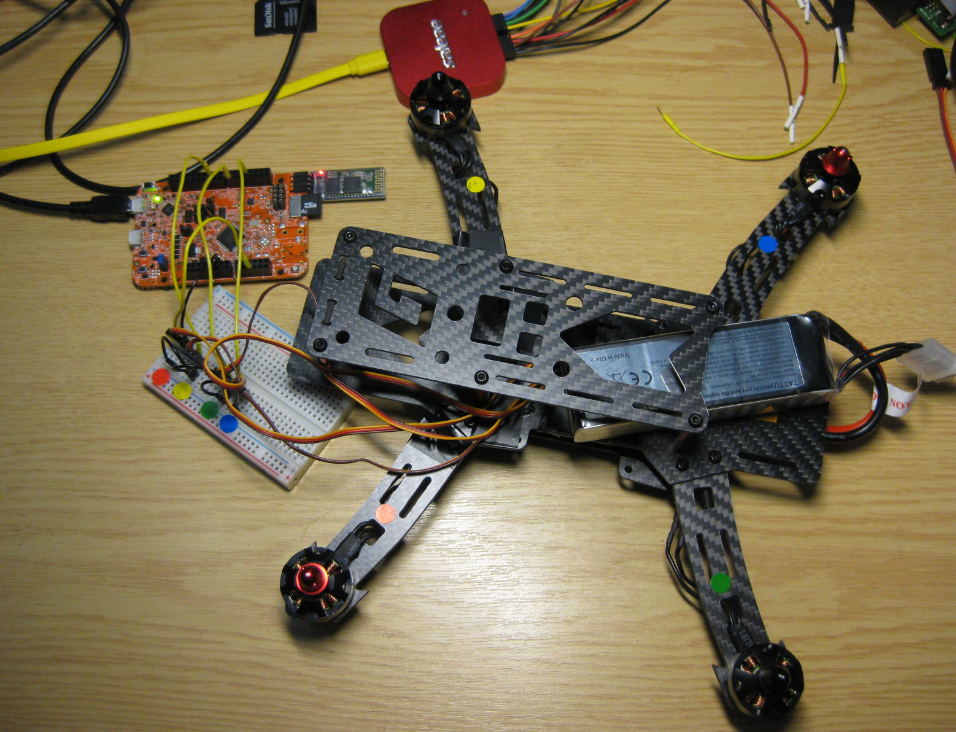
FRDM-K22F with Quadrocopter
4 PWM components are setup to drive the motors:
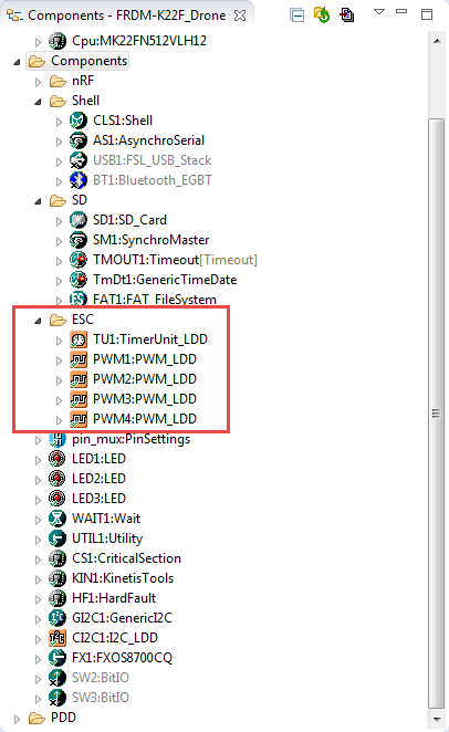
ESC Components
With a Shell/Command line interface over USB CDC and Bluetooth I can control all ESC’s:
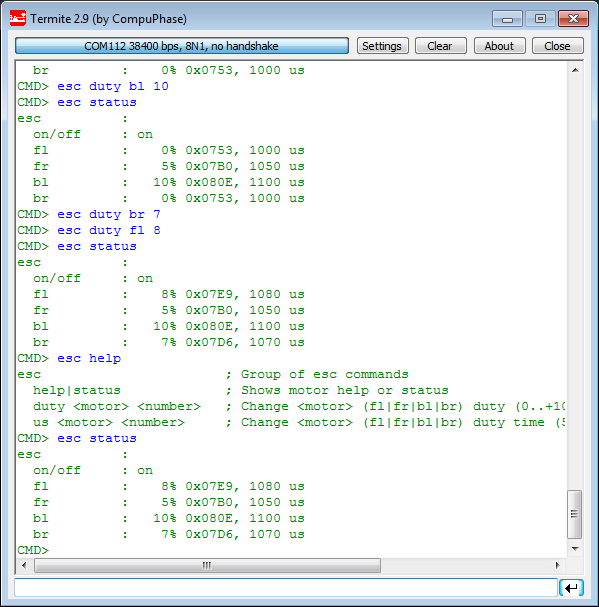
Shell to control the ESCs
Summary
Using an ESC makes it easy to drive a brushless DC motor for a quadrocopter: I need to supply a PWM signal to the ESC, and the ESC will drive the motor.
Next step will be to use the gyro, magnetometer and accelerometer on the FRDM-STBC-AGM01 with the FRDM-K22F. The current state of the project is posted on GitHub.
Links
- Assembling the Quadrocopter frame: “Kinetis Drone: Frame Construction with Graupner Race Copter Alpha 250 Q“
- Graupner S3055 ESC: http://shop.graupner.de/webuerp/AI?ARTN=S3055
- Graupner Race Copter Alpha 250 Q: http://shop.graupner.de/webuerp/AI?ARTN=16520.HOTT&SessionCheck=4711&language=en
- Freescale FRDM-K22F Board: http://www.freescale.com/products/arm-processors/kinetis-cortex-m/k-series/k2x-usb-mcus/freescale-freedom-development-platform-for-kinetis-k22-mcus:FRDM-K22F
- Freescale FRDM-STBC-AGM01 Board: http://www.freescale.com/tools/embedded-software-and-tools/hardware-development-tools/freedom-development-boards/frdm-stbc-agm01-9-axis-inertial-measurement-sensor-board:FRDM-STBC-AGM01
- OpenPilot project: https://www.openpilot.org/
- Link to the project on GitHub: https://github.com/ErichStyger/mcuoneclipse/tree/master/Examples/KDS/FRDM-K22F/FRDM-K22F_Drone
- Calibrating ESC’s: http://robots.dacloughb.com/project-2/esc-calibration-programming/

Pingback: Kinetis Drone: Graupner ESC S3055 Failure | MCU on Eclipse
Pingback: Kinetis Drone: Remote Controller with SUMD | MCU on Eclipse
Hey man, i’ve been thinking about starting my own drone with controlled by an arm mcu but i was wondering: Does every esc need a separate battery or can you power the 4 of them with just one?
LikeLike
Hi Kevin,
You can use one battery with multiple ESC’s. Only make sure that the battery is able to provide enough current for all of them.
LikeLike
wow i didn’t notice the time difference between us, Mr. Erich, i thought that i was going to get an answer tomorrow haha. So if i have 4 30A ESC, i need a 120A battery?
LikeLike
Yes, your battery has to provide that in the worst case.
LikeLike
I see, thanks Mr. Erich, helpfull as always. I love your blog by the way, it’s been really useful this semester. Greetings from Mexico
LikeLike
Pingback: Kinetis Drone: First Test Flights | MCU on Eclipse