Freescale/Farnell/Element14 announced last week a new Freedom Board: the FRDM-K20D50M :-). As you can expect, I was not able to resist, and ordered one from my local Farnell store right away. So I did my first steps with it on this sunny and wonderful weekend (yes! we skipped Spring Time and entered Summer Time right away!).
I do not need to compare the board with the previous Freedom boards, as I have found an article here. I a nutshell: I get pretty much the same as with the FRDM-KL25Z, but instead of an ARM Cortex-M0+, it has an ARM Cortex-M4!

The new FRDM-K20D50M Board
Farnell.ch sold me the FRDM-KL25Z for CHF 17.05, while the FRDM-K20D50M is listed for CHF 32.25. That’s about twice the price of the FRDM-KL25Z :-(. Ok, I get an ARM Cortex-M4 instead of an ARM Cortex-M0+, but what else? Let’s see.
The Content
The board comes in the typical Freedom board, only that it the board is a red one:

FRDM-K20D50M Box and Content
The box includes a small bag with the 4 dual-row headers. Nice! That justifies at least some of the higher price.

Dual Row Arduino Headers
The Board
The front side of the board looks very familiar to the existing FRDM boards:

FRDM-K20D50M Front Side
Having a closer look, there are a few more add-ons:
- There are two crystals: one 32 kHz and one 8 MHz one.
- New analog Ambient Light Sensor with J12 jumper to isolate it
- New Temperature Sensor (U11) with jumper J13 to isolate it (Note: the user manual says that this sensor is *not* populated. However, it is present on my board 🙂 )
- Two jumpers (J16 and J17) to disconnect the I2C lines to the accelerometer
- Jumper J14 to cut the reset line between OpenSDA and the target CPU
- Jumper J13 to isolate the BD1020HFV-TR temperature sensor
- Jumper J21 to enable USB Host support (unprotected), so my hack is not needed any more 🙂

Changes on board compared to FRDM-KL25Z
On the backside the battery holder is not populated (same as on earlier Freedom boards):

FRDM-K20D50M Backside
I noted that many pins on the dual row headers are marked as NC (Not Connected). So J9 could have been a single row header (which would be cheaper?).
Software
Freescale provides at this link an updated OpenSDA package plus bare-metal source code and examples. The source code package is not what I need in the first place as I already have a lot of drivers with Processor Expert, but always good to have such a package.
The Quick-Start Package (FRDM-K20D50M_QSP.zip) has an updated OpenSDA debug application and mass storage bootloader.

FRDM-K20D50M Quick Start
The board has the same OpenSDA on-board debug connection, so I had first to load the Debug Application (same procedure as for the FRDM-KL25Z: press the reset button on power-up, load the OpenSDA Debug App, re-power the board).
I loaded that new DEBUG-APP and I do not remember which one was factory installed. Anyway, that v106 worked for me and CodeWarrior for MCU10.3
First Project with CodeWarrior
Using CodeWarrior for MCU10.3, the MK20DX128VLH5 (mask 1N86B) is supported in the Wizard:

MK20DX128 in the CodeWarrior Wizard
The OpenSDA connection is not available in the connection page of the Wizard. But this does not matter, as the normal P&E Multilink connection works. I only have to change the Interface in the debugger settings from P&E Multilink to OpenSDA:
💡 To get to the dialog below: menu Run > Debug Configurations, press ‘Edit…’ button on the Connection in the ‘Main’ tab of the debug connection.

OpenSDA Debug Connection for FRDM-K20D50M
❗ Do not forget to enable the ‘SWD’ debug option. I missed to set this option in the first place, and then the debugger reported “ERR: Can not enter background mode” 😦
Running FreeRTOS
Running an emtpy bareboard application was just a matter of minutes. To use more of the board ressources, I added the FreeRTOS operating system, Shell over OpenSDA CDC and RGB LED support to it:
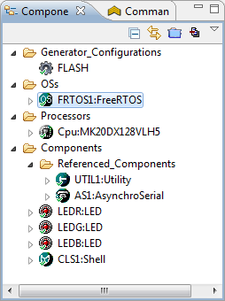
FreeRTOS and other components
All what I needed to do is to configure the RTOS and assign the proper pins for the LED and serial connection. With Processor Expert this took less than 10 minutes from start until I had a shiny toggling LED on my board 🙂 :
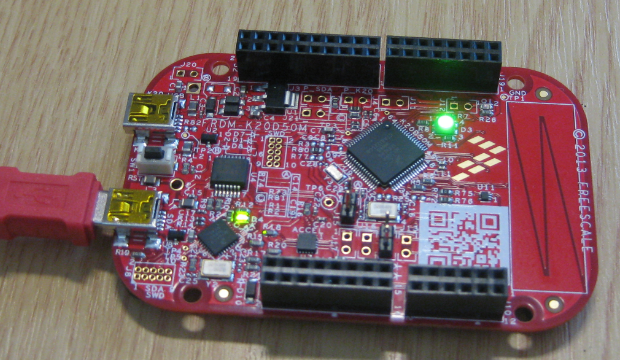
FreeRTOS running on the FRDM-K20D50M, with headers populated
The CodeWarrior project is available on GitHub here and will be extended over time.
Summary
That new Freedom board adds a Cortex-M4 to the existing FRDM-KL25Z and FRDM-KL05Z. It comes with the headers, plus temperature and ambient light sensor. While the M4 provides more horse-power, I wish it would have more than 16 KByte of RAM. Especially as STMicroelectronics has the STM32F3Discovery board with an ARM Cortex M4, 256 KByte of Flash and 48 KByte of RAM for CHF 25.55, compared to the CHF 32.25 for the FRDM-K20D50M? On the other side: there is no Processor Expert for the Discovery Board ;-). I think these days it is the software which makes the difference, not the silicon or the board. Silicon is only sand 😉
I’m happy with what I was able to carry out with the board in a very short time. It is a great addition to my set of boards, especially as it can interface with Arduino (compatible) shields. And I want to run my Zumo with it so I have a little red+black robot :-). That will be a lot of fun: I already have some ideas how to use the temperature and ambient light sensors :mgreen:.
Happy Boarding 🙂
PS: Yes, I had a beautiful and sunny week-end *outside*. Processor Expert enabled me to spend many hours outside with my family. Thank you! Despite the fact that I catched a light sun burn 😉

STM32 has perfect peripheral libraries. Very well documented and easy to use – way better approach than processor expert.
LikeLike
I became less faithful to Freescale chips when I wanted more RAM and more UARTs. Right now I’m in limbo. I found that in PIC32, as Erich stated, software is everything and the Microchip tools are just awful. The debugger is unusable for any large project.
I’m now experimenting with the STM32 ARM chips. I find the STM32 libraries to be awkward to get used to. And certainly not without bugs. But I love the added elbow room, Flash code space and RAM especially of their chips. 192K RAM on the STM32F4 Discovery. That is a decent eval board, for USD $15 from Digi-Key.
I find things don’t seem to be thought through we well though as Freescale. For example the STM32F3 and F4 versions of the Discovery boards have a just slightly different pinout. Enough so you can’t make “shields” that work on both.
I guess I still like the overall Freescale experience better.
LikeLike
Hi Bill,
@But I love the added elbow room, Flash code space and RAM especially of their chips.
What about the NXP M4/M0 Combination with 1MB Flash and 264 kB SRAM, if you really need more Memory?
Evaluation Board : € 73,- (incl. SD-Card, Audio, USB-Host etc.)
http://de.farnell.com/jsp/search/productdetail.jsp?SKU=2148863&MER=baynote-2148863-pr
LikeLike
Hi Erich,
found the drawings at the Farnell Product page …
Yes, 3.3V is connected to VBat-Pin via J15!
This is really ‘good News’ …..
LikeLike
Hi Reiner,
yes, I only have found it on http://www.element14.com/community/solutions/8950/l/freescale-schematics-for-the-freedomfrdm-k20d50m
LikeLike
Erich,
I agree, Processor Expert is really indispensable once you have used in an entire project… then there is no turning back (rest is just sand indeed!). I wish there was more consistency between 8-bit components vs. Kinetis LDD components.
I am always amused when certain unique hardware features of MCUs become a reason for a its choice. Especially hearing from folks disciplined about code portability across vendors, but just throwing this portability out of the window due to a specific MCU uniqueness.
Your Processor Expert examples have been very helpful. Keep up the great work!
-Irwin
LikeLike
Hi Irwin,
Yes, these LDD introduced with Kinetis (see https://mcuoneclipse.com/2012/07/26/there-is-a-time-and-date-for-both-worlds/) was breaking my hard work to keep things compatible across different platforms and microcontrollers. I pushed hard on getting the ‘High Level Beans’ back. The good news is: they are (mostly) back with MCU10.3, so I’m pretty much back on track.
In my lecture, students develop a closed loop motor control application, and they use the same software with S08 (8bit), ColdFire V2 (32bit, Big Endian) and Kinetis-L (KL25Z Freedom board, Little Endian). With Processor Expert this is easily possible.
Thanks for your feedback,
Erich
LikeLike
Hi Erich,
I have this board, and I’m trying to get it working with Eclipse / CodeWarrior / ProcessorExpert. I use Eclipse all the time for enterprise Java, Ruby and C development, but the CW and PE additions make it look and operate very differently. I downloaded and installed “Special Edition: CodeWarrior for Microcontrollers 10.3 (Eclipse, Online)” from http://www.freescale.com/webapp/sps/site/prod_summary.jsp?code=CW-MCU10&fpsp=1&tab=Design_Tools_Tab – I hope this is the correct version.
I have tried following your Processor Expert “quickstart” ( https://mcuoneclipse.com/2012/03/09/quickstart-for-processor-expert-in-eclipse/ )in conjunction with this article but so far I am not able to run any code. I was wondering if you could help at all?
I know the board and the USB connection are working, as I was able to update the bootloader and drop in the example programs as described in the Quick Start package. I created a PE project and saved/built it without problems, but when I tried to run the debugger It gave an error because it can’t find the target board. After a lot of hunting around, I found something which looks like the “OpenSDA Debug Connection” dialog you show above, but even though I have selected OpenSDA and clicked “refresh” it still refuses to find any valid USB devices to communicate with.
Can you think of anything else I might be missing? Can you suggest any other ways to check the connection between the IDE and the board? I also have a KL05Z and a KL25Z knocking around if you think one of those might be better to start with…
Many thanks for any help,
Frank.
LikeLike
Hi Frank,
the OpenSDA is either in MSD Bootloader mode (this is what I think you have), or in Debug mode. In Bootloader mode it enumerates as MSD/Memory stick, so you can copy S19 files. But in order to debug it, you need to load the DEBUG-APP_Pemicro_v102.sda (or later). Then the debugger can connect to it.
See https://mcuoneclipse.com/2012/09/20/opensda-on-the-freedom-kl25z-board/
I hope this helps.
LikeLike
Thanks very much for the quick and helpful response, Erich.
I went through the bootloader process again and this time I got it right. I think what I might have done wrong was to try and install the Open SDA Debug App as a regular application (by dragging it to the K20D50 MSD) rather than as a bootloader app (by dragging it to to the BOOTLOADER MSD)
I now have a simple Processor Expert program running on all three of my Freedom boards!
LikeLike
Hi Frank,
you are not alone with this. I have seen many users confused or trapped by the fact that for debugging there is a different application needed.
LikeLike
Pingback: Using the Freedom Board as JTAG Programmer | MCU on Eclipse
Pingback: Debug External Processors with USBDM and Freedom Board | MCU on Eclipse
Pingback: USB CDC with the FRDM-K20D50M | MCU on Eclipse
Good Morning,
You stated that, to use the OpenSDA, “change the Interface in the debugger settings from P&E Multilink to OpenSDA.” Where is the screen located (what menu selection)? I have searched through every menu item that seemed logical, and I can’t find the Connection screen.
Thank you,
John
LikeLike
Hi John,
Sorry, as I’m dealing with the debug connections all the time, it was clear to me. But clearly, that might not be the case for everyone.
It is in the connection settings of the launch configuration: Use the menu Run > Debug Configurations, press ‘Edit…’ button on the Connection in the ‘Main’ tab of the debug connection.
I have updated the post with that information, so thanks for asking!
LikeLike
Thank you. Although I have been using CodeWarrior, and Processor Expert for about five years, I have only used the P&E programmer/debugger, and never needed to change the connection. The OpenSDA could be a good option for teaching (the students would not need a separate programmer).
LikeLike
Yes, the OpenSDA is a excellent thing for me and the students: a) only one USB cable required b) that cable provides power c) that cable is the debug connection and c) that cable serves as USB CDC terminal connection. 🙂
LikeLike
hi erich great blog. I just received my k20d50m, I’m wanting to use your freertos project as a baseline for going forward and tweaking stuff. I’m having trouble understanding how to open a project from your github. I’m new to eclipse/codewarrior/processor expert. I’m having a hard time finding example projects to start from just to get comfrotable with the ins and outs of the board…any tips would be appreciated.
LikeLike
Hi ghosty,
thanks 🙂
Have a look at the Wiki pages here: https://github.com/ErichStyger/mcuoneclipse/wiki
The easiest is if you download the zip file from GitHub (https://github.com/ErichStyger/mcuoneclipse/archive/master.zip), then unpack it into your Processor Expert working directory (it is C:\ProgramData\Processor Expert\CWMCU_PE5_00 on my machine). Restart Eclipse.
Then you can import (or drag&drop) the K20d50 FreeRTOS project into the Eclipse IDE.
I hope this helps to get you started.
LikeLike
thanks for the tips. I got the environment setup thanks to your link. i have a some questions about your freertos project. Is this just a blank project where you can setup tasks and do whatever you want in the application code. I was trying to look at an old in depth example you had of using free rtos, but it was an older freedom board and older version of CW and looked like you were setting up tasks in main(). I bought this board hoping to get some experience of using an rtos (freertos) and I saw this post and thought it was perfect. Is there a version that has the blinking LED already setup and running within the RTOS project. The most helpful to me is to be able to load a working project, and slowly read through and understand and make changes little by little to understand the rtos and board. Trying to use the freertos project is a little more complex than using the freescale demos, but I think will be better for ongoing tinkering and setting a better foundation for more complex projects. Can you post the blinky rtos project, or provide a quick run through of adding simple blinky LED tasks to the template project in github? Is this project good to go as is except for tasks? I’m a little sketchy on when i see your examples changing a bunch of configurations in the freertos component, but those are older examples and this project is specific to this board no? Thanks for the help, and honestly this is a great blog, your dedication and detailed posts are great.
LikeLike
Hi ghosty,
what do you mean with ‘older’ Freedom board? The FRDM-KL25Z?
The FRDM-K20_FreeRTOS project just has a little bit more than the blinky LED with FreeRTOS (it uses the accelerometer, shell and shell trace), but that’s very easy to rip off.
For a really simple blinky-LED-with-FreeRTOS see https://mcuoneclipse.com/2012/09/29/tutorial-freedom-with-freertos-and-kinetis-l/, with the project available here: https://github.com/ErichStyger/mcuoneclipse/tree/master/Examples
If the tasks are in ProcessorExpert.c or in its own source file, really does not matter. I recommend that you take some time to go through the sources, and I hope things are not too complicated for you to learn.
The projects I discuss or the sources for the tutorials in this blog are available on GitHub (https://github.com/ErichStyger/mcuoneclipse/tree/master/Examples), and it is possible to download all of them as a single zip file (with the Processor Expert components in it). Please read the wiki pages (https://github.com/ErichStyger/mcuoneclipse/wiki).
I hope this helps.
LikeLike
yes, I meant the previously released M0 freedom board. I grabbed FRDM-K20_FreeRTOS and it obviously has other stuff in there. I expected it to be a working project I could use as a starting place. I tried to build it and I get errors. is that a larger scale freetos work in progress and i shouldn’t expect it to build out of the box? I’ll try building up a blinky rtos project following the link you provided. thanks
LikeLike
Hi ghosty,
yes, that project should work out of the box, *but* you need the Processor Expert components present/installed. I’m just guessing that you missed that step maybe?
LikeLike
no, i’ve added the components fine. here is a pic of the build errors i’m getting. something to do with the declaration of taskENTER_CRITICAL(); and taskEXIT_CRITICAL();
Now I can try to debug it, but i imagine it’s something i’m doing wrong with not generating processor expert code or something along those lines that I’m unfamiliar with this IDE or processor expert or it looked like if these aren’t declared for the “additional” modules besides the LED ones that i grabbed the repository when you were in the middle of adding features and i shouldn’t expect it to build.
So my next step was going to be build up freertos blinky led project for this board from scratch using the processor expert components and try that way, but since you confirmed this project should build as-is, i’m curious about what I’m doing wrong, because i have imported the PE stuff to it’s install folder and that’s all fine i believe.
LikeLike
Hi ghosty,
that looks like the linker complains about this. Not sure why this is happening to you.
taskENTER_CRITICAL() is a macro in task.h:
#define taskENTER_CRITICAL() portENTER_CRITICAL()
portENTER_CRITICAL() again is a mcro in portmacro.h:
#define portENTER_CRITICAL() vPortEnterCritical()
and vPortEnterCritical() is defined in port.c.
The fact that the linker/compiler is complaining about taskENTER_CRITICAL() tells me that somehow I2C1.c does not include task.h.
I2C1.c includes this through
#include “FreeRTOS.h” /* FreeRTOS interface */
then FreeRTOS.h includes task.h on line 85:
#include “task.h” /* << EST: for taskENTER_CRITICAL() and taskEXIT_CRITICAL() */
So to me it looks like you have not the latest and greates FreeRTOS Processor Expert component files?
Can you check if you have the above include of task.h in FreeRTOS.h file located here:
C:\ProgramData\Processor Expert\CWMCU_PE5_00\Drivers\freeRTOS\FreeRTOS.h
?
I'll send you an email with the FreeRTOS component as *.PEupd file to make sure you have the right files installed.
I hope this helps.
LikeLike
Thanks, I grabbed your latest commit to github and updated the PE drivers and beans and tried the updated project and it built fine. so it fixed that, i dunno what the deal was, i literally grabbed it the day i posted having trouble…dunno, but thanks for the help. tried it real quick before i head to bed and It built, so now begins my digging and learning time starting tomorrow (need sleep…going to pass out). Again appreciate the help and love the blog.
LikeLike
Glad to hear that things seems to work out. Related to this, I have just published *.PEupd files (see https://mcuoneclipse.com/2013/05/09/processor-expert-component-peupd-files-on-github/) so this should hopefully make things easier for everyone.
LikeLike
Pingback: USB MSD Host for the FRDM-K20D50M Board | MCU on Eclipse
Hi Erich
Congratulations with your book!!!
I´m working in a project with CANbus, I want a freescale microcontroller, the FDRM-K20D50M is a good option but the uController I need is this: http://mexico.newark.com/freescale-semiconductor/mk20dx64vlh7/mcu-kinetis-k20-cortex-m4-64lqfp/dp/27W5244?in_merch=Popular%20Products. If I remove the original Cortex M4 from the board ¿Can I program and debug this other “micro” whith the FDRM-K20D50M?
Thanks Erich
LikeLike
Hi Alets,
thanks 🙂
I don’t think you will be able to use the on-board OpenSDA if you change your processor, with the original OpenSDA firmware. You need a different firmware e.g. Segger (https://mcuoneclipse.com/2013/05/16/freedom-board-with-segger-opensda-debug-firmware/) or USBDM (https://mcuoneclipse.com/2013/04/27/debug-external-processors-with-usbdm-and-freedom-board/) for this.
LikeLike
Pingback: A new Freedom Board: FRDM-KL46Z | MCU on Eclipse
Good Afternoon,
I have been using CodeWarrior and Processor Expert for about 5 years, and this has never happened before. I created a new project for the FRDM-K20D50M board (CodeWarrior V10.4). It compiled with no errors; it downloaded to the board; and it ran fine (it was just in a for loop).
Next I selected the PWM component. I wanted to make the LED flash, so I configured it for PTC3 FTM0_CH2 with a 500 ms period and 250 ms pulse width. When I try to compile the project the following error appears:
The Processor Expert project MK20 Test was NOT generated because of some error. See Problems view for more details.
The Problems view states:
Generator: FAILURE: at line 8: Unknown macro: “TmrName” (file: Drivers\Common\PWMSettings.inc
I have used the PWM component many times before on Coldfire processors, and have never had a problem. Does anyone have any idea what is wrong? This should be simple.
Thank you,
John Murphy
LikeLike
Hi John,
I have not seen something like this neither.
Could you check if you have that file inside this folder:
C:\Freescale\CW MCU v10.4\MCU\ProcessorExpert\Drivers\Common
?
Maybe it helps if you close and re-open the project?
It looks like the timer name is a problem, so maybe selecting another timer might get that error going away?
If you want (and can), you can send me that project to my email address on the about page of this blog, and I have a look from my side.
LikeLike
Well, after working on the problem for several hours, and then posting this question, I found the solution – project names cannot contain spaces. At least, I think that was the problem. As soon as I removed the space in the project name, everything worked. I always used spaces in earlier Coldfire projects, so this did not occur to me. The error message was also not very helpful.
Anyway, thank you. I think that just taking the time to write down the problem, and getting away from Coldfire for a few minutes helped.
LikeLike
Filenames with spaces again. Nothing but trouble. 🙂
Once in the early ’80s I managed to create a Unix filename of just a Ctrl+G bell character. That was a weird one.
LikeLike
good catch! I have not thought about this one. But of course these kind of things have teached me that I avoid spaces. But that error message is really odd and would not point to the right problem.
LikeLike
The other odd thing is that the project compiled, downloaded, and ran in the debugger until I tried to add the PWM component. That is what really threw me off track.
LikeLike
Hi John,
I was able to reproduce your problem and have it submitted to Freescale so they can have a look. Interestingly it seems to work for other components (project with spaces), but not for the PWM component.
LikeLike
It’s Back.
The error has returned, and now there are no spaces in the project name.
I am trying to use the Pololu Dual MC33926 Motor Driver Shield with the FRDM-K20D50M (the FRDM-K20D50M is supposed to be compatible with Arduino Shields). The PWM signals for the motor driver shield are on PTA2 and PTC2 (corresponding to FTM0_CH7 and FTM0_Ch1).
When I first configured the PWM for PTA2, there was an error because the pin interfered with the JTAG. I am using the SDA, so I disabled the JTAG, and the error disappeared.
Now, when I configure PTA2 as a PWM, and then try to compile, I get:
Unknown macro: “TmrName” (file: Drivers\Common\PWMSettings.inc)
This is the same error that appeared when there were spaces in the file name. Interestingly, I can set up PTD4 (FTM0_CH4) as a PWM, and blink the onboard LED, with no errors. This also works when the JTAG is disabled, so that is not the problem.
In summary, if you set up PTD4 as a PWM, and have spaces in the project name, the “unknown macro” error appears. If you get rid of the spaces in the project name, the error disappears; and PTD4 works properly as a PWM. If you set up PTA2 as a PWM, the “unknown macro” error appears, even with no spaces in the project name.
Sorry for the long post. Any help would be greatly appreciated.
Thank you,
John Murphy
LikeLike
It’s getting stranger.
If PTC3 FTM0_CH2 is configured as a PWM, everything works fine. If PTD4 FTM0_CH4 is configured as a PWM, everything works fine. If PTA2 FTM0_CH7 is configured as a PWM, the “unknown macro” error appears, and nothing works. At this point, PTC3 and PTD4 stop working as PWMs. If you reboot the computer, the project works again, including PTA2, until you try to configure, or reconfigure, another PWM. At that point, you need to reboot the computer again to make it work.
I have tried this several times, with the same results. At least there seems to be a work-around (rebooting frequently), but it is a long work-around.
LikeLike
John,
that’s really strange. I have asked my contact in Freescale, so hopefully he could help out. As for the workaround: when I have seen strange things with Processor Expert (expecially errors not going away), it helped to right click on the project and close it, and then re-open it. This triggers re-loading of the file, and this worked in my cases. Not sure if this helps you, but rebooting the machine definitely is not good.
LikeLike
While thinking more about this one, and you say that reboot helped. I know that Processor Expert generates some temporary files inside the windows temp folder (for me it is C:\Users\\AppData\Local\Temp). I clean that one up on a regular base. Maybe you have so many files in it, that this causes your problem? I have not tried your ‘advanced’ steps, but I was able to get the same error as you with creating a project with spaces, and then adding the PWM component. Just in case the cleaning of Temp might help.
LikeLike
I have tried using “Clean,” but it doesn’t help. Sometimes, just closing CodeWarrior and then reopening it works, but not always. I will try closing and then reopening the project but, for now, there are no errors and I am afraid to change anything.
Eventually, after a lot of rebooting and restarting, I did get the Pololu Dual Motor Driver Shield working properly. I am using a 200 us period, which produces a pretty steady output.
LikeLike
Yes, agreed not changing it. Clean would not help in my view, as this would remove the object files/make files, and does not touch Processor Expert.
LikeLike
Please could you tell me which is the way for disable JTAG in Codewarrior? Thanks!
LikeLike
Hi Carlos,
check the Cpu component properties: for some microcontrollers you can explicitily disable the JTAG pins. Otherwise map them to general purpose I/O pins. Depending on what you have in mind with this, there are pros and cons of this approach. If you want prevent access to the microcontroller, then securing the microcontroller is a better way.
LikeLike
Pingback: Showcase of Student Project Exhibition 2014 in Horw | MCU on Eclipse