
It always takes longer than expected: actually 4 weeks from the first board out of the reflow oven (“First New Zumo Board out of the Reflow Oven“), until I have it working on the Pololu chassis. But now I have a mobile Robot with WiFi, GPS, Bluetooth, nRF24L01+ and all the stuff I have dreamed off 🙂
New Zumo Robot
Many reasons for this, but the main reason was that there was too much solder paste/cream used, and with this especially the processor soldering was not good. After a lot of tweaking (thanks to Christian Jost!) things are mostly ok now. The on-off circuit needed some tweaking too, and now works as it should :-).
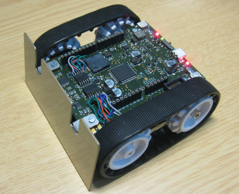
The big change to the previous design (see “Zumo Robot Assembled“) is that the processor (Freescale ARM Cortex M4F running at 120 MHz) is embedded on the board, and instead using Pololu plug-in modules, the H-Bridge and 5V and 3.3V DC-DC converters are embedded on the board. That way the robot height is much smaller, because there is no need to add a Freescale FRDM board on top of the base board.
Bewlow is a picture with the new robot on the left (with Bluetooth module) and on the right the previous robot design with an Ultrasonic sensor on the front:
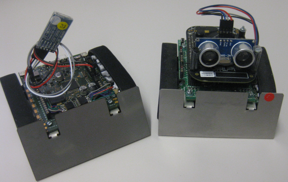
New and Previous Zumo Robot
I have not added the extra sensor and wireless connectors (distance sensors, Bluetooth, IEEE802.14.2 and nRF24L01+ to the base board, because I can add them with a commercial or custom shield.
Main Features of the new robot:
- Freescale Kinetis K22FX512 ARM Cortex-M4F USB processor, 120 MHz, 512 KByte FLASH, 64 KByte RAM. Brain of the robot running with USB interface (bootloader, USB CDC)
- Freescale FXOS8700 I2C Accelerometer and Magnetometer (see “Review: New FRDM-KL26Z Board“)
- Two Pololu 1:75 Micrometal Gear motors with extended shafts (Pololu #2215), with optical Quadrature Encoders (Pololu #2591)
- Microchip MPC6004 Linear Op-Amp and Microchip MPC4728 I2C DAC converter to process the quadrature signals (see “Processing the Pololu Motor Shaft Encoders“)
- Texas Instruments DRV8835 Dual H-Bridge, same as on Pololu #2135, able to drive two DC motors with 1.2A continuously
- Sounder using PWM to play tunes.
- Pololu Zumo Chassis (Pololu #1418) with compartment for 4 AA Batteries
- Pololu Zumo Front Blade (Pololu #1410)
- Pololu Reflectance sensor Array (Pololu #1419)
- 5V DC and 3.3V DC converters

Zumo Robot Assembled with major components

Battery compartment with Pololu Reflectance Sensor behind Blade

Power (green) and User (red) LEDs

Chassis with Motors

Motor with Optical Encoder

Board Bottom Side with Motors
Removing the need for the Freescale FRDM board on the robot as in the previous design now makes it possible to stack normal Arduino boards on the robot. The pictures below show the robot using the Adafruit GPS Shield (see “Tutorial: Freedom Board with Adafruit Ultimate GPS Data Logger Shield“) and the Adafruit WiFi shield, making the robot really easily extensible with off-the-shelf shields:

Robot with Adafruit WiFi Shield

Robot with Adafruit GPS Shield
💡 for the next version of the board we need to move the headers to the back a little so the shields fit behind the front blade.
I need to complete more system tests, and we already have a list of smaller board changes. The plan is to finish next week-end and then to produce the final batch of boards for the next semester, starting mid of September. Time is running….
💡 Still thinking about how many boards to produce and populate. If there is any interest to get a board, let me know and I can count this into the number of units to order. No guarantees, of course.
Happy Sumoing 🙂

Hi Erich…
Therefore you have created/translated a library/component/driver to use the CC3000 device (WiFi module of TI) on Kinetis environment?
I have buyed, some time ago, the CC300 Adafruit shield, but i dont have enough time to develop anything with a FRDM board…
Bye
LikeLike
Hi Antonio,
Yes, that work is in progress to use the CC3000 from TI. Not finished yet.
LikeLike
Pingback: Sensor and Communication Shield for Sumo Robot | MCU on Eclipse
Pingback: Comparing CodeWarrior with Kinetis Design Studio | MCU on Eclipse
Pingback: New Sumo Robot PCBs Arrived! | MCU on Eclipse
Pingback: New Sumo Robot Assembled, and looking good! | MCU on Eclipse
Pingback: Using Kinetis Design Studio V3.0.0 with the Launchad 4.9-2015-q2 Release | MCU on Eclipse
Pingback: Zumo Robots at Maker Faire in Rome (16. – 18. Oct. 2015) | MCU on Eclipse
Pingback: 2017 Spring Semester Sumo Challenge | MCU on Eclipse
Pingback: Making Perfect Sticky DIY Sumo Robot Tires | MCU on Eclipse