
Finally I have found some time over the past week-end to enhance my Zumo robot. After I had my line following robot based on the Pololu Zumo chassis and the FRDM-KL25Z, I thought it should be easy and logical to solve a maze. Logical: yes. Easy: not that much. In fact it took me longer than expected. As always, there are a lot of tiny and important problems to solve (the maze alone was easy 🙂 ).
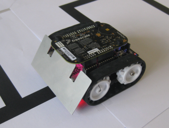
Zumo in the maze
The Maze
Similar to the line following task, the robot has to follow lines, which build up a maze with an end point. The lines are straight, but could have round forms too. There are turns (left and right), and intersections (‘T’ formed or ‘+’ formed). The job of the robot is to find the finish marked with a large filled area and to learn the maze. After the robot has found the finish area, it has calculated the way without dead ends. Now the robot can travel the direct (not necessarily the shortest) path to the finish.
Note: To simplify things, there are no loops in the maze 🙂 To solve a maze with loops, I would need a way to measure the segments with an encoder or something similar.
A good introduction how to implement the maze solving algorithm is found on the Pololu web site.

Maze
There are several ways to construct a maze. Instead of using black tape for the lines, I used large laser printed paper with black lines. I taped them together to build a larger maze. To start, I used a simple ones like this:
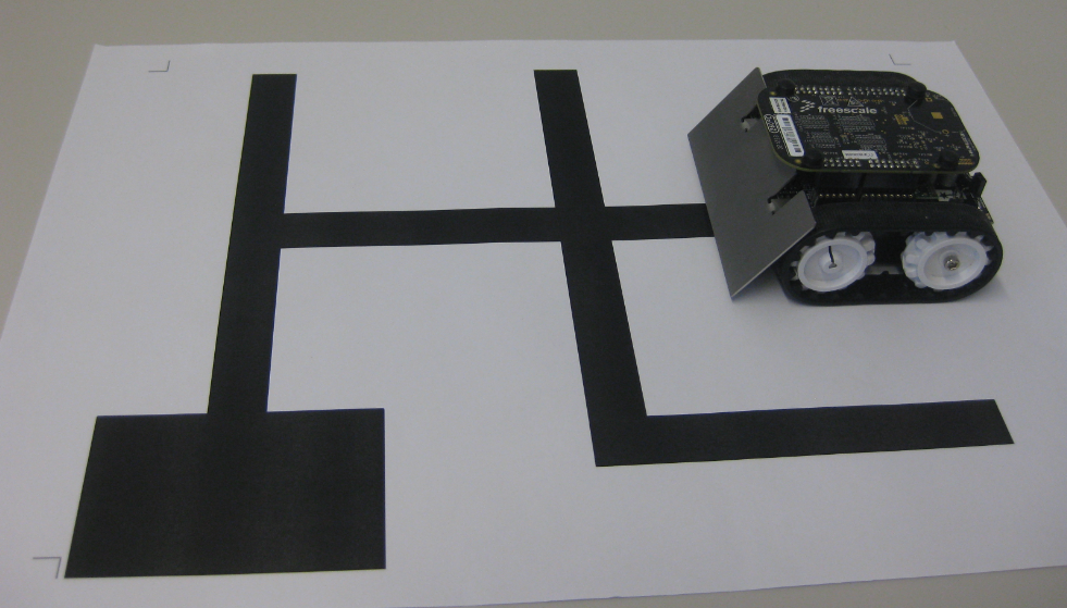
Practice Area for the robot
The Project
The project is using the GNU ARM compiler for Kinetis-L with CodeWarrior for MCU10.3 It is using may different Processor Expert components, including a command line shell and running FreeRTOS.
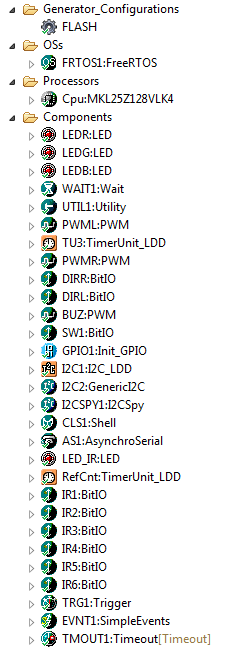
Processor Expert Component for Maze Solving
The shell offers the following commands to control the robot (either with OpenSDA USB CDC, or with a Bluetooth serial bridge if attached to the robot):

Shell Commands
That way I can inspect easily the status of the system and control the robot:

System Status
The full application needs about 53 KByte of Flash without any compiler optimizations. With -Os this shrinks down to about 33 KByte of Flash, so easily fits into the CodeWarrior free code size limit of 64 KByte.
The Video
The robot is using a ‘left-hand-on-the-wall’ approach: it traverses the maze and always turns left if possible, until it reaches the finish. While traversing the maze, it simplifies the path. Once found, the robot starts again and it will follow the simplified path.
Steps with the robot to solve a maze:
- Putting the robot on the start line.
- Pressing the push button for 3 seconds to enable auto-calibration.
- To ‘learn’ the lines and to calibrate the sensors, it performs a left and a right turn on the line.
- Another press of the push button starts the line following program.
- The robot follows the lines with a ‘left-hand-on-the-wall’ algorithm, while simplifying and removing loops detected.
- Once it finds the finish, it stops
- Moving the robot back to the start and pressing the button will let if follow the direct path to the finish 🙂
And here is a video:
Summary
There are a few things I have learned with this project:
- Things take more time than expected 🙂
- Even if things are working out fast at the beginning, and it seems ‘mostly’ to work, this does not mean that nearly all issues are solved :-(.
- Never underestimate problems with sensors. Depending on the laser printer and paper used, the reflections were different, caused a lot of guessing on my end why the sensors do not work all the time reliably.
- Use a high enough PWM signal. I used a lower frequency 100 Hz PWM signal to the motor H-Bridge, resulting in some turns not properly taken or not taken at all. It took a while to find the root of the problem. Increasing the frequency to 100 kHz solved that issue :-).
- Be aware of sensor time-out: I had a 20 ms timeout for my sensor readings. With truly black areas, that limit was easily reached with incomplete sensor readings. Using a 2 ms timeout and proper handling solved that problem.
- Generate bread crumbs for debugging: used the command line shell built-in, transmitted messages over Bluetooth, or using an extended USB cable. Everything to ‘see’ what is going on.
- In case of the application crashes or blocks, using the CodeWarrior Attach helped me to inspect what was going on in the system.
- Make the first runs on the floor, and *not* on a table. That robot is not made to fly.
- Always stay on the line :-).
The CodeWarrior project is available as open source project on GitHub.
As always, I have many improvements im mind:
- Higher speed 🙂
- Using the magnetometer for better turning control.
- Optimization of the small step forward at every dead-end found.
- Using the PID to tune the turning on an intersection or dead-end.
- Ability to return from the finish to the start automatically.
- Exploring the full maze to find the smallest path.
- Using dynamic speed: running faster on the long straight lines, while slowing down near the intersections.
Happy Mazing 🙂

wow, looks nice! even tho i’m a networking guy i don’t understand much you writing about but this little roboter amazed me ^^ and i can see now a fancy usage for this freedom board
keep up!
LikeLike
Don’t worry, I have a a TCP/IP stack port on my to-do-list already 🙂
LikeLike
Pingback: Maze solving FRDM-KL25Z Robot goes backward for Dead-Ends | MCU on Eclipse
Pingback: Adding Quadrature Encoder to the Zumo Chassis | MCU on Eclipse
Pingback: Zumo Robots at Maker Faire in Rome (16. – 18. Oct. 2015) | MCU on Eclipse