
While developing applications, it can happen that things go wrong. And in my case I ended up with two LPC55Sxx EVK boards on my desk, which seemed not to be usable any more. The issue: the boards were not accessible with the debug probe, because right after main they muxed the pins in a wrong way :-(.

The standard GDB debug connections (both on-board and off-board) were not able to regain access of the board, because the MCU was running into the fault condition pretty much right out of reset.
Luckily, after a lot of trial-and-error, I have found a way to recover them.
The problem occurred while developing a custom LCD/OLED driver for the LPC55S16-EVK board. Suddenly the board did not respond any more because I had the pin muxing wrong. So I ended up to continue developing with the LPC55S69-EVK, only having that board ‘bricked’ soon again.

Each debug probe had different ways to report the error, and for the J-Link it is especially this one:
ERROR: Could not connect to target.
SEGGER J-Link GDB Server V7.62b Command Line Version
JLinkARM.dll V7.62b (DLL compiled Mar 8 2022 15:15:34)
Command line: -nosilent -swoport 2332 -select USB=609100567 -telnetport 2333 -singlerun -endian little -noir -speed auto -port 2331 -vd -device LPC55S16 -if SWD -halt -reportuseraction
-----GDB Server start settings-----
GDBInit file: none
GDB Server Listening port: 2331
SWO raw output listening port: 2332
Terminal I/O port: 2333
Accept remote connection: localhost only
Generate logfile: off
Verify download: on
Init regs on start: off
Silent mode: off
Single run mode: on
Target connection timeout: 0 ms
------J-Link related settings------
J-Link Host interface: USB
J-Link script: none
J-Link settings file: none
------Target related settings------
Target device: LPC55S16
Target interface: SWD
Target interface speed: auto
Target endian: little
Connecting to J-Link…
J-Link is connected.
Device "LPC55S16" selected.
Firmware: J-Link V9 compiled May 7 2021 16:26:12
Hardware: V9.10
S/N: 609100567
Feature(s): RDI, FlashBP, FlashDL, JFlash, GDB
Checking target voltage…
Target voltage: 3.30 V
Listening on TCP/IP port 2331
Connecting to target…
ConfigTargetSettings() start
Disabling flash programming optimizations: Compare, SkipBlankDataOnProg
ConfigTargetSettings() end
InitTarget() start
ERROR: Wrong DM-AP IDCODE detected: 0xFFFFFFFF
InitTarget() end
ConfigTargetSettings() start
Disabling flash programming optimizations: Compare, SkipBlankDataOnProg
ConfigTargetSettings() end
InitTarget() start
ERROR: Wrong DM-AP IDCODE detected: 0xFFFFFFFF
InitTarget() end
ConfigTargetSettings() start
Disabling flash programming optimizations: Compare, SkipBlankDataOnProg
ConfigTargetSettings() end
InitTarget() start
ERROR: Wrong DM-AP IDCODE detected: 0xFFFFFFFF
InitTarget() end
ConfigTargetSettings() start
Disabling flash programming optimizations: Compare, SkipBlankDataOnProg
ConfigTargetSettings() end
InitTarget() start
ERROR: Wrong DM-AP IDCODE detected: 0xFFFFFFFF
InitTarget() end
ERROR: Could not connect to target.
My usual recommendation is to try with different debug probes: that’s why I always have a set of SEGGER J-Link, NXP McuLink, NXP LPC-Link2, P&E Multilink or even BlackMagic debug probes available. But in this case: none of them were able to directly regain access to the board using the GDB debug connection.
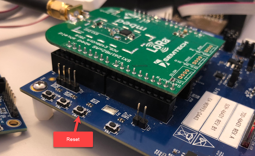
What ultimately solved the problem was a combination of the SEGGER J-Link Lite Flash programming tool plus the Reset button. For this I used an external debug connection using a J-Link:

Locate and start the SEGGER JFlashLite:
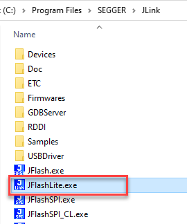
Start it, then select the correct device used (LPC55S16 in the case below).
Press the ‘Erase Chip’ button: this probably won’t work, so try again and again, while pressing the Reset button on the board: With this, after some trials, it should succeed:

After that, I was able to debug the board(s) again :-).
Bottom line is: a reset button on a board can be worth gold. Plus having as many different debug probes and tools helps for sure too.
So if you end up in the same situation, I hope you find this article and it helps you out. If you own a P&E Multilink, you can use the same approach or using the more advanced power glitching method (see Recovering Cortex-M Microcontroller with a Power Glitch).
Happy recovering 🙂

Is there no ISP mode? I thought it was mentioned here https://www.nxp.com/doc/AN12283.
LikeLiked by 1 person
Good point! Yes, there is an ISP mode. I suspect that this would have helped too (need to verify). I would have used that as next step if SWD would not have helped.
LikeLike
I can confirm I used ISP mode many times on this family exactly for this purpose
LikeLiked by 1 person
Hi jobe,
thanks for confirming! Although I believe the debug/SWD connection shall be able to recover from such a situation as well. At least this is how it does on on other families. Not sure why it does not work that way for the LPC (at least 55xx one)?
Erich
LikeLike
Also worth considering a jumper shunt connected to a spare GPIO in your hardware; then early in your SW, read the GPIO and if it’s fitted then call some ROM API commands to erase the flash 😉
LikeLiked by 1 person
Yes, that’s an excellent idea. I usually add a ‘safety line’ delay in the code at the start to have a chance to regain the target.
LikeLike
Was the nRST line not connected to your probe? Surely that allows more repeatable, control over that “reset button”. Also, some chips actually have functionality exposed while in reset, allowing activation of the SWD interface. e.g. https://research.kudelskisecurity.com/2020/04/15/swd-part-3-swo-and-nrst/
LikeLiked by 1 person
Yes, it is connected, and my thinking would have been that this should do it to, if the debug probe pulls the reset line. But all the debug probes I had were not able to recover it that way somehow. Not sure why.
LikeLike
If they switch to using an external clock before setting up the pins, you can short the external clock. That will allow the debugger to take control of the chip to reflash it.
LikeLiked by 1 person
That a really good idea! Thanks for the suggestion.
LikeLike
Hi Erich and Eclipsers,
The LPC5500 ROM security makes situations like this a bit tricky, because the debug port isnt enabled until the ROM decides its safe/appropriate to do so, and that can mean the debug system cant communicate with the MCU fast enough after resetting it in order to get control. ISP mode is one way as the ROM will tidy everything up then go to the ISP routine to allow debug control to happen; however you may need to assert ISP while powering up to ensure all possible I/O conditions are really at the default state.
A handy way to recover from a bad application is to use the debug mailbox erase. This allows MCUXpresso IDE to instruct a mass erase of flash directly. Its supported for any of the probe types, and there is a shortcut for each (Linkserver (LPC-Link2/MCU-Link), J-Link and PE) next to the “Debug your project” section in the Quickstart section. Select “Erase flash action” from the menu that pops up when you click on one of these icons.
Finally, if you really want to understand how the debugger does a handshake with the secure ROM on these devices, check out the debug chapter (from memory, I think its Chapter 56 for LPC55S6x). We put quite a bit of effort into explaining this – most users (except our tool partners) don’t need to know or care, but for some it might be helpful 🙂
Thanks
Brendon
LikeLiked by 1 person
Hi Brendon,
many thanks for all the details, appreciated! I was not aware that the ‘flash erase’ action could be used for this. I certainly will try that next time. I know that for Kinetis there is a dedicated recovery action in the programming section, so adding this to other devices certainly would help users to try that thing.
LikeLike