OpenPnP is a great open source framework for building a DIY SMT Pick&Place machine. But it does not stop there: It is possible to use OpenPnP with a commercial pick & place machine, for example the Charmhigh CHM-T36VA. This Chinese machine comes with its own controller software which works but is not that great. The good news is that it is possible to hack and retrofit the machine so it can run the much more powerful OpenPnP.

Retrofitted CHM-T36VA
Outline
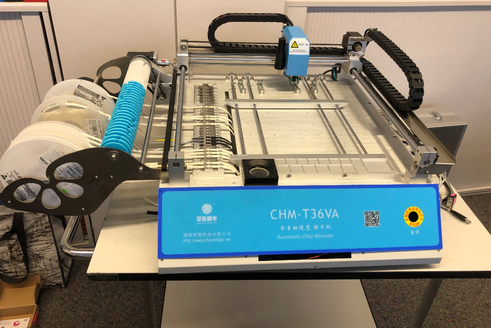
This article describes how to retrofit the Chinese Charmhigh CHM-T36VA machine. That machine is available on AliExpress for around $3300. For that price this is a bargain: a good machine with dual-vision and dual pick&place head. The machine requires an extra host PC (e.g. notebook) (there is the T48 model which can run standalone). While the machine is pretty decent, the software/firmware is not that great. SparkFun is using that machine too and has created a wealth of knowledge and even a translated manual in a git repo (https://github.com/sparkfunX/Desktop-PickAndPlace-CHMT36VA) to overcome most of the issues. The OpenPnP framework is much better and has more features.
💡 Warning: modifying the machine as explained in this article will clearly void the vendor warranty, and cannot be reverted (except buying a new controller board from Charmhigh!). So only do this if you are confident and sure that you want to do it!
CHMT and OpenPnP
The OpenPnP community started looking into using OpenPnP for that CHMT machine back in 2019.
Jason von Nieda (founder of OpenPnP) started a project reverse engineering the protocol (see https://www.gofundme.com/f/help-openpnp-grow) which almost succeeded: except it was not possible to rotate the nozzles with that protocol.
Matt Baker then decided to port the Smoothieware to the STM32 controller inside the CHMT machine. Thanks to Matt this port is available on GitHub: https://github.com/mattthebaker/Smoothieware-CHMT
This article describes some of the details how to migrate the CHMT to OpenPnP. Basically, the steps are:
- Upgrading the machine hardware (Cameras, Cable Drag Chains)
- Building Smoothieware and flashing new the firmware
- Machine configuration
The Wiki on https://github.com/openpnp/openpnp/wiki/CharmHigh-CHMT36VA is a good starting point and the reference for such a retrofit.
Cable Drag Chains and USB Extension Cables
I ordered 2m of the 15×20 mm semi-open version: https://www.aliexpress.com/item/32838858814.html?spm=a2g0s.9042311.0.0.27424c4dQBxGzt
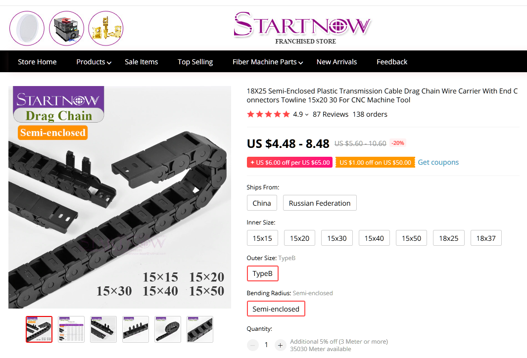
drag chain
3 USB Extension Cables (1.6-2.0m) are recommended to order too. They are used to extend the USB cables from the cameras.

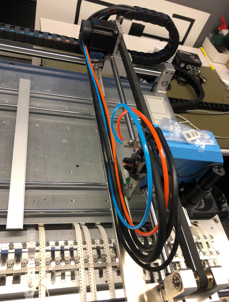
Drag Chains with USB Extension Cords
The existing drag chains need to be removed and the new ones installed for replacing the top camera USB cable.

cutting off the existing drag chain
Removed existing drag chain
The advantage of the semi-open one is that it can be easily opened later for adding new cables.
Semi-Closed Drag Chain
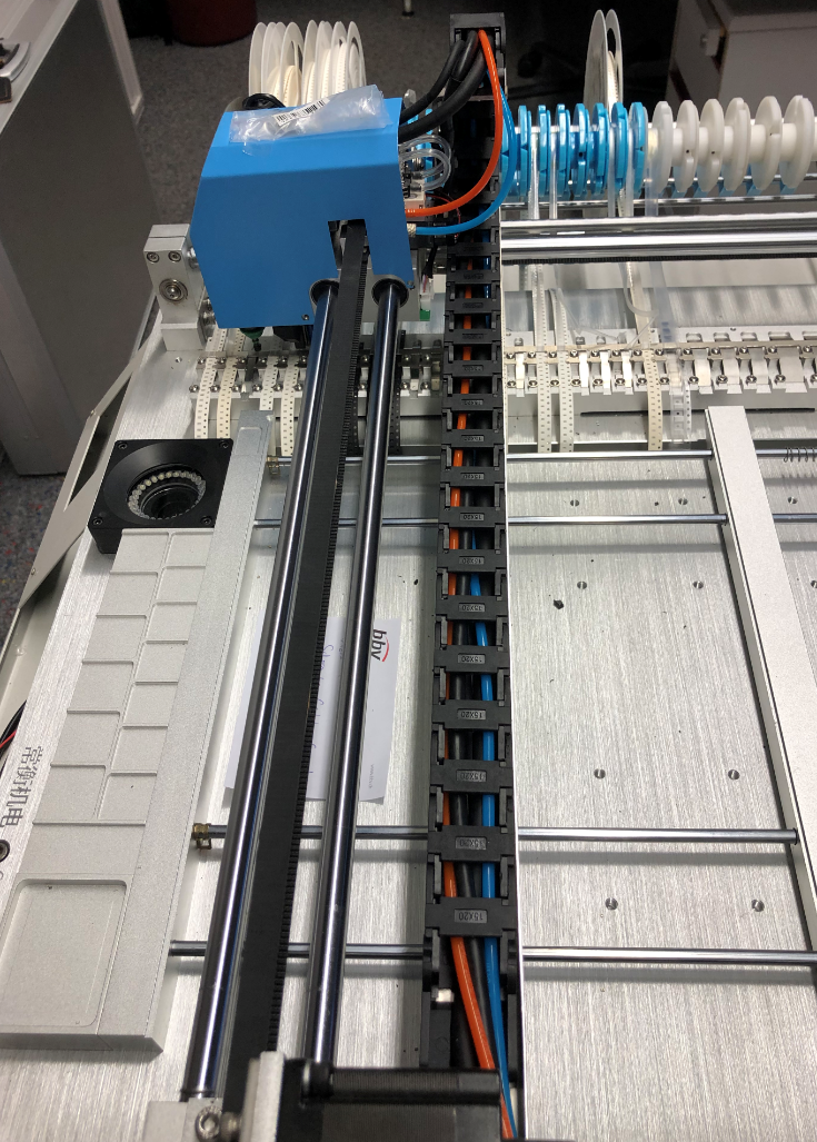
Closed Semi-Open Drag Chain
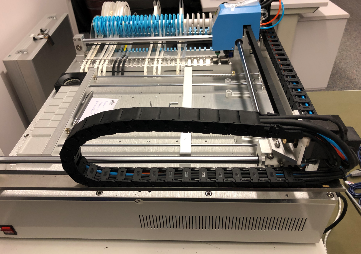
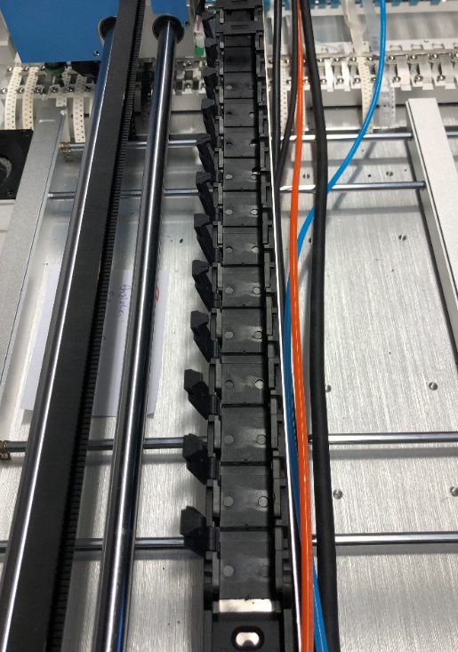
Installed New Drag Chains
Make sure the chains are moving smoothly: they are tied to the bottom guiding plate in the middle.
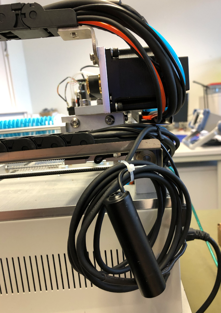
Cameras
I decided to update the two cameras (bottom (up looking) and top (down looking) cameras. It should be possible to keep the existing cameras (see https://github.com/openpnp/openpnp/wiki/SwitcherCamera).
Up-Looking Camera
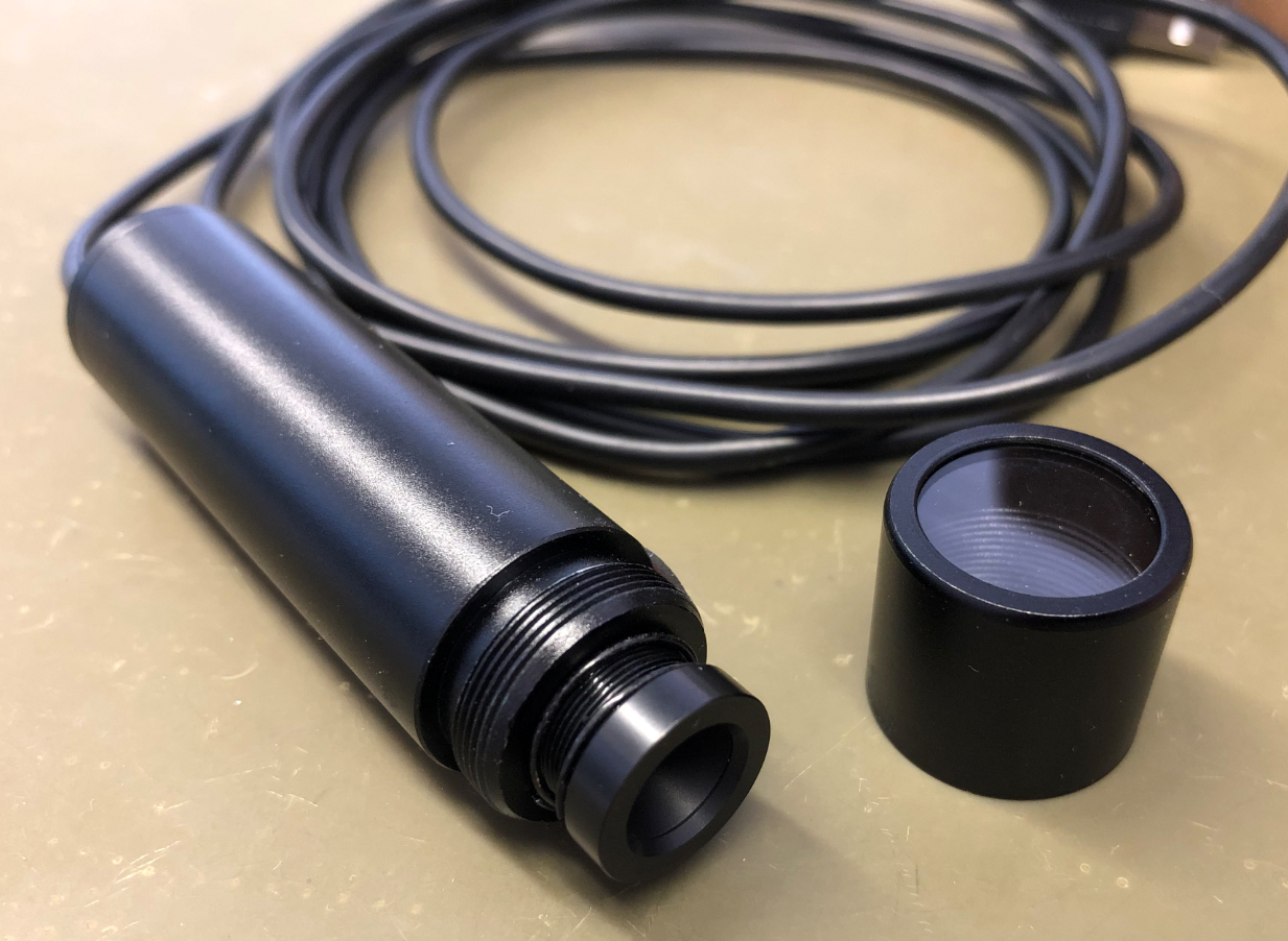
For the bottom camera I ordered the ELP global shutter camera, in the 2.8-12 mm lens option: https://www.aliexpress.com/item/33015394467.html
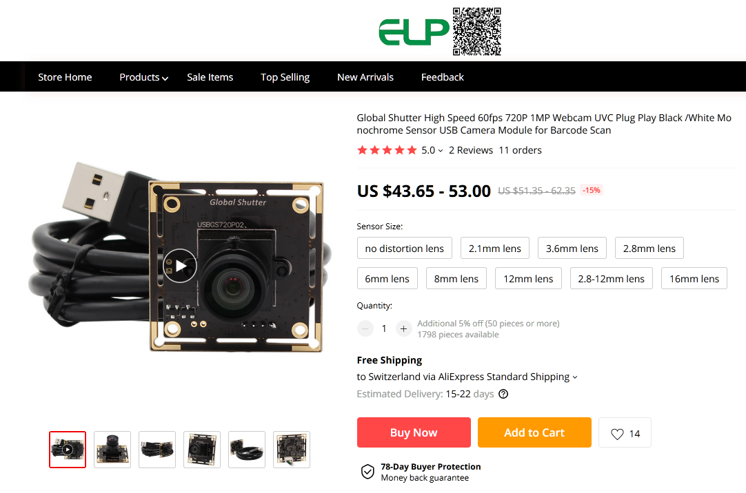
ELP global shutter camera
As a ‘global shutter’ version it captures all the pixel in one step which is ideal for moving targets. The camera is greyscale only as no color is needed.
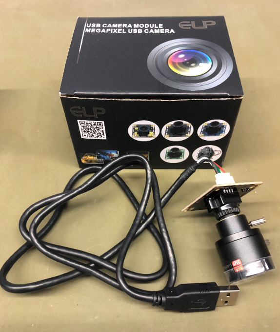
ELP Camera
The up looking camera LED ring is attached to the base with hex screws:
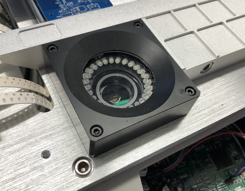
Up looking Camera LED Ring
Remove the LED ring:
Removed LED Ring
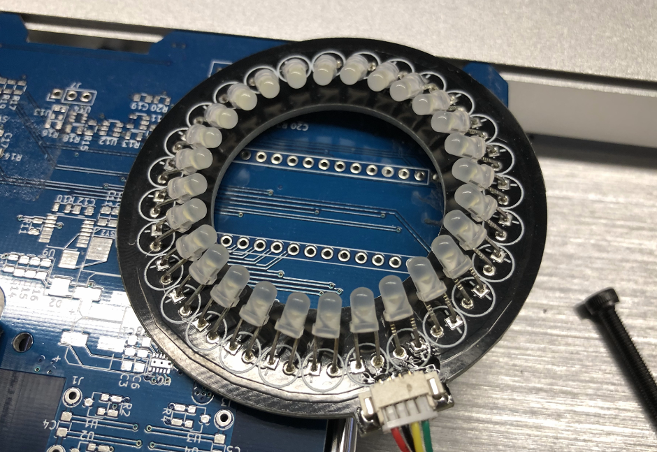
LED Ring
Remove the 4 screws of the bottom camera:
Hex Screws of bottom Camera
Bottom Camera removed
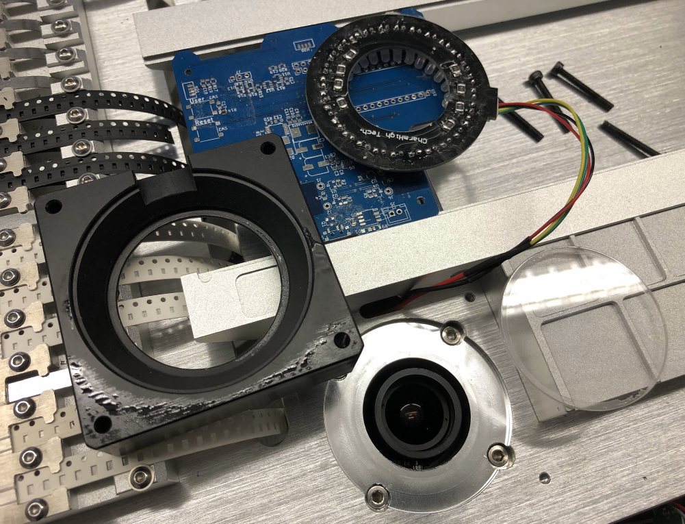
We need to take out the original camera, so open the four screws in the corners:
Bottom Camera Bottom Side
On the side there are hex screws to release:
Camera Enclosure Hex Screw
Original Camera taken out
You might re-use the lens screws on the side for the new camera as the camera enclosure is tight. Take the new camera and put it into the enclosure. Before putting everything back, make sure the lens is accessible and focused on the right distance.
New camera in the enclosure
I used black electrical tape make sure the LED ring is isolated from the enclosure:

Electrical Tape for Bottom LED Ring
Attach the USB extension cable to camera cable and route the cable to the back side of the machine (USB connector).
Nozzles
I had to color the green original nozzle color with a black pen:
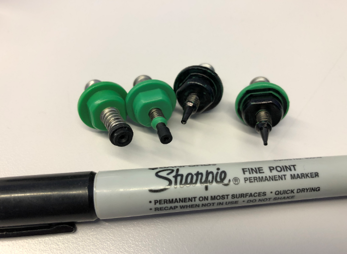
Painting Nozzles Black
💡 I highly recommend to order spare nozzles.
The idea is to have a black background as much as possible and have to ‘shine’ the part and its pads. That way parts got perfectly recognized.
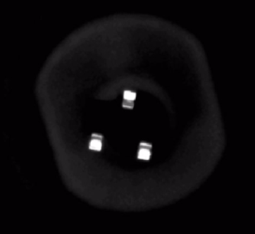
SOT-23
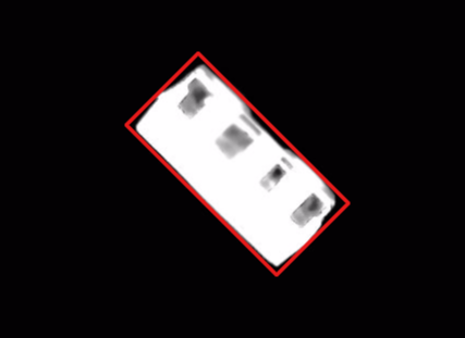
Below an example of an 0603-capacitor seen from the bottom vision pipeline:
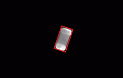
0603 capacitor
Here an example of a WS2812-SIDE LED:
WS2812B-SIDE
I’m using the following settings for the bottom camera:
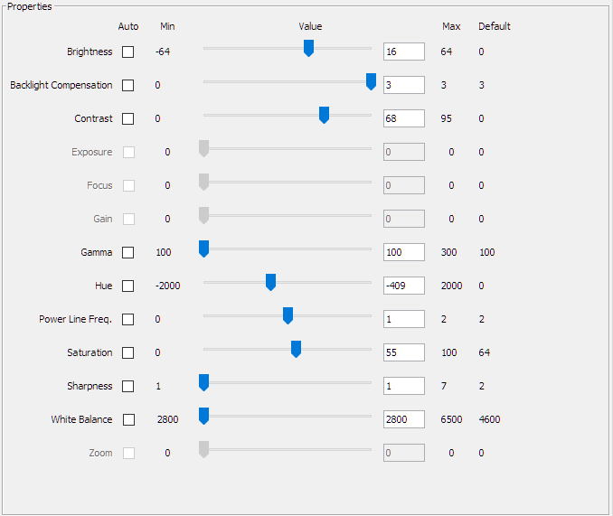
Bottom Camera Settings
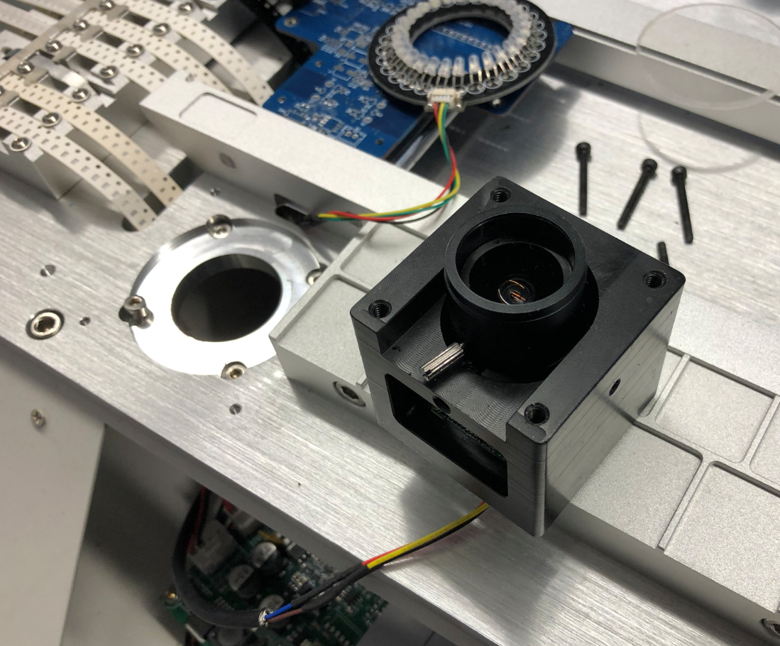
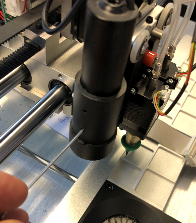
Down-Looking Camera
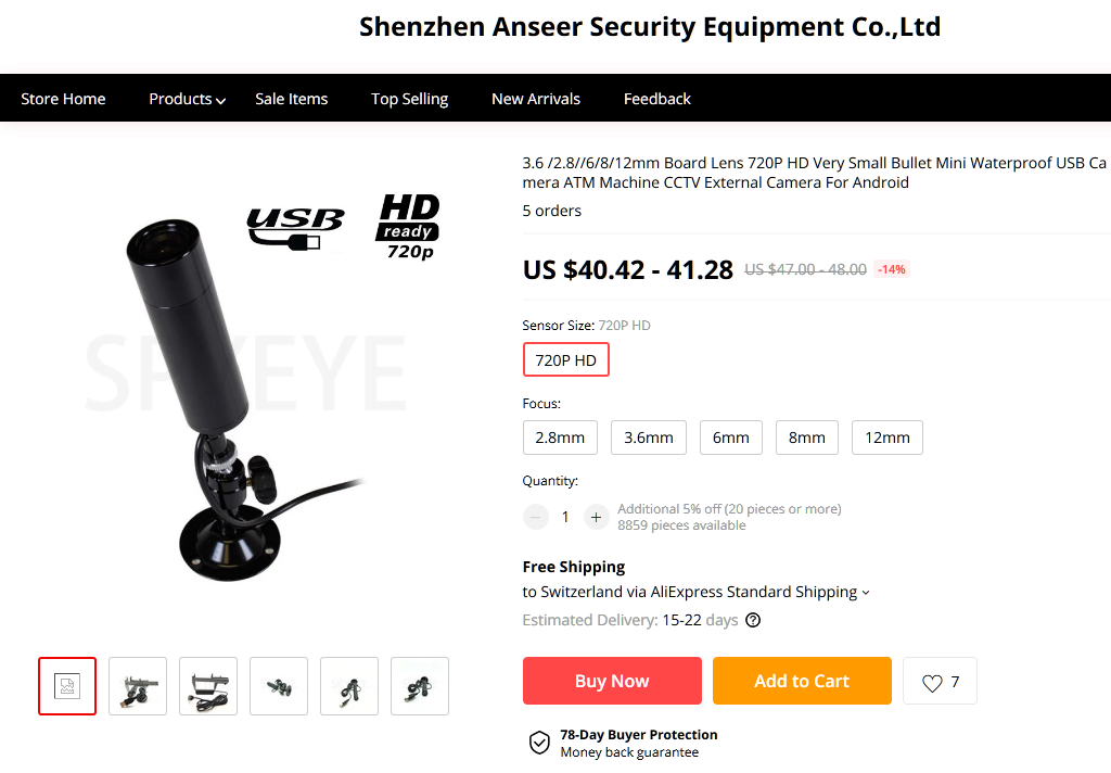
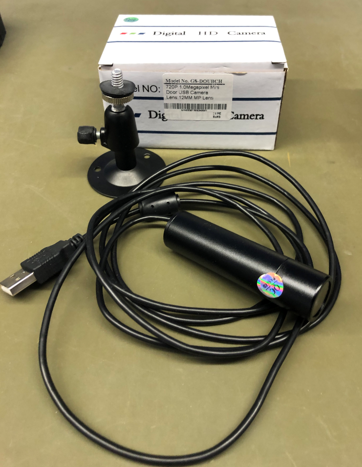
For the down looking camera I ordered this one with a 12 mm lens:
https://www.aliexpress.com/item/32892346870.html
Aliexpress Down Looking Camera
💡 If needed, the 8 mm lens from the original camera can be used. I’m using the 12 mm lens, but this makes the view area rather small, so I might switch back to the 8 mm one.
Downlooking Camera
12mm Lens on camera
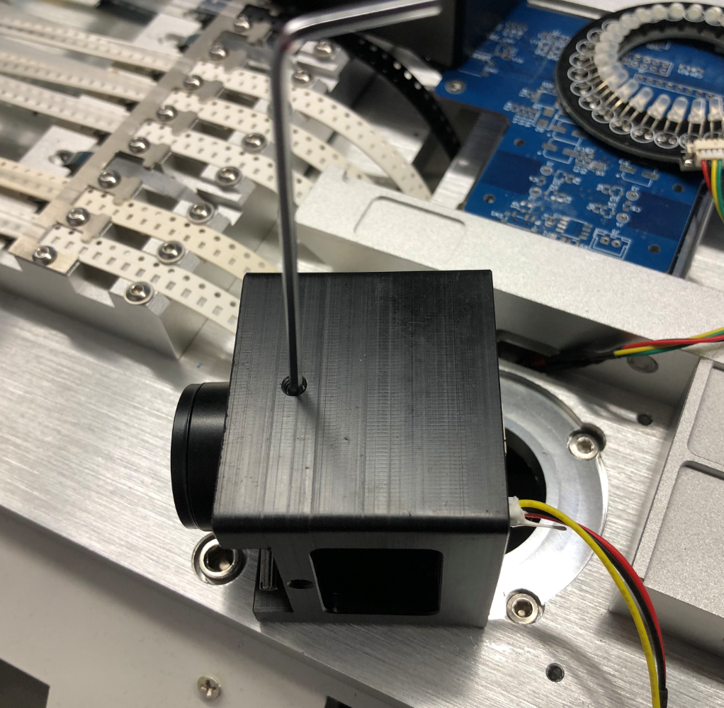
To remove the original camera, use a small hex tool:
Removing original down camera
I did not cut the cable of the original camera immediately, just in case. The camera can be removed after finishing the retrofitting.
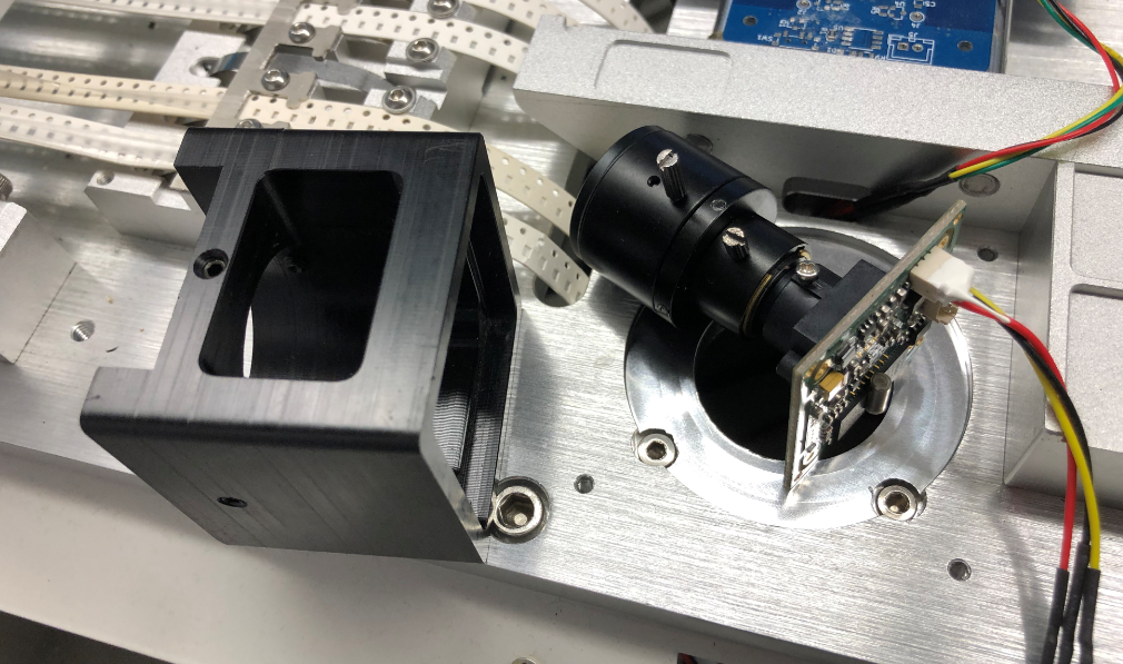
Removed camera
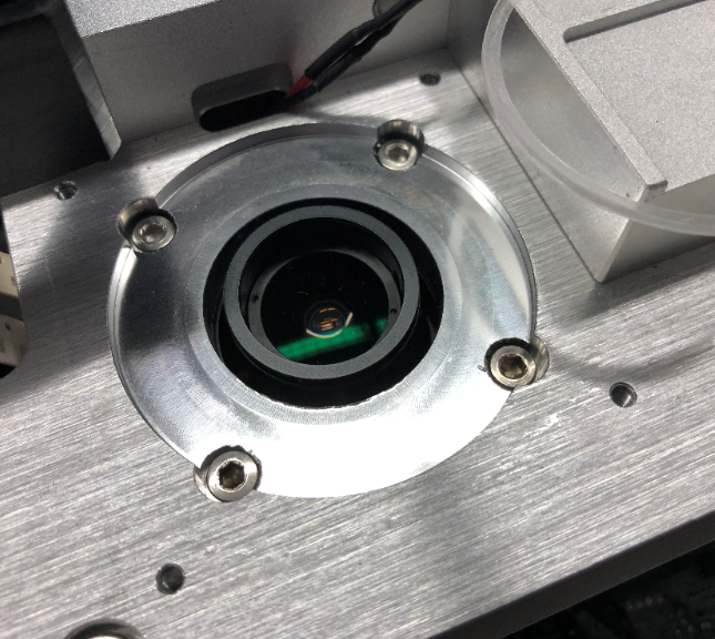
Make sure that the new camera head/lens does not crash into the park position. Make sure it fits above the home position aluminum block:

New Camera in Park Position
Use the USB extension cable to extend the cable through the cable chains (or cut the cable and solder a longer one, this is what I did in the end to have more flexible cable chains).
The main job of the top camera is recognizing the fu
iducials on the board to adjust the board position and rotation. Below the views of a 1 mm fiducial with the top camera and 12 mm lens:
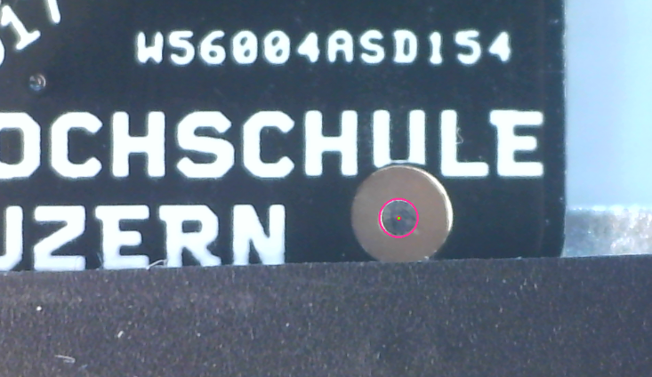
Fiducucial
Fiducial
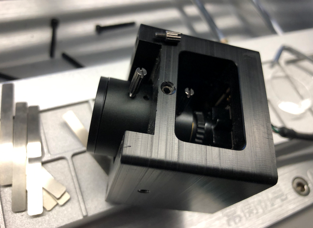
Controller Board
To access the internals of the machine, remove the front cover of the machine. The screws are behind the front plate:
CHM-T36VA with Front Cover
Inside the machine there is the controller board. Below a picture with the board detached from the bottom screws:
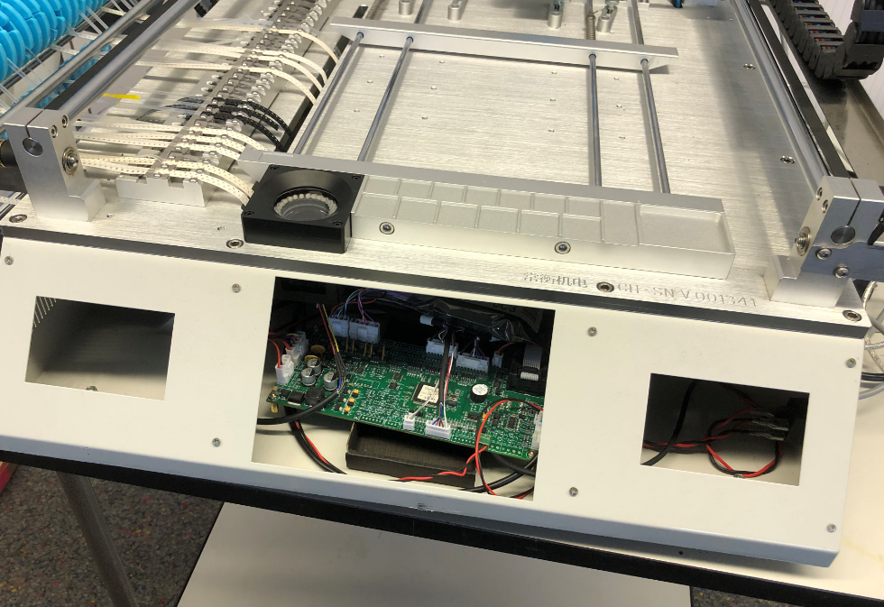
CHM-T36VA Controller Board
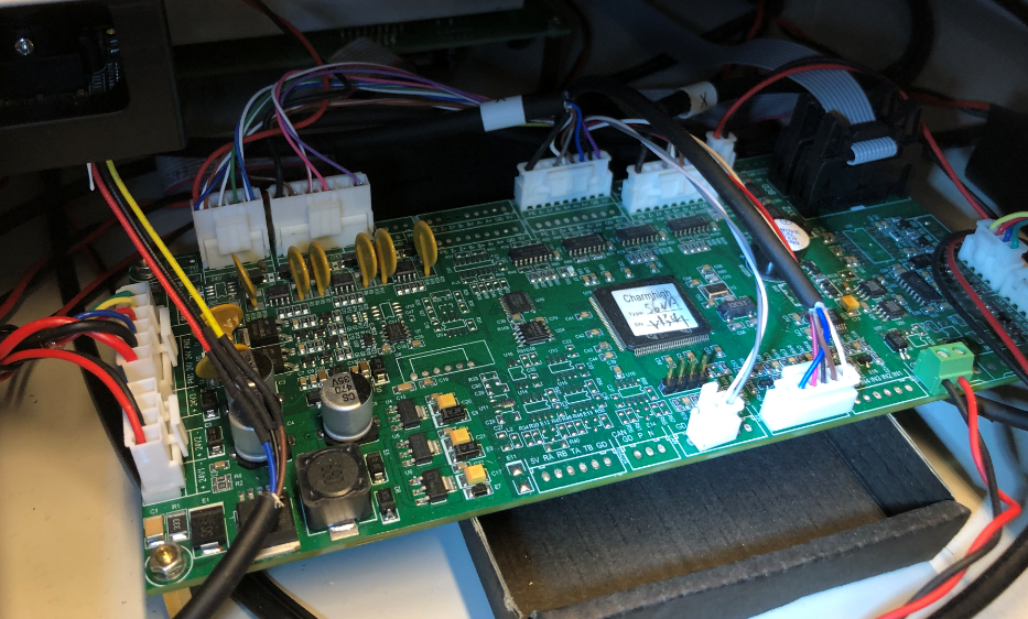
Controller Board
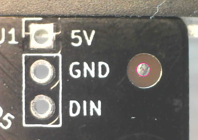
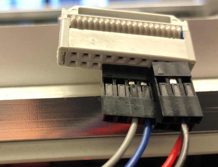
The 4pins in the front of the board are the pins of the debug header.
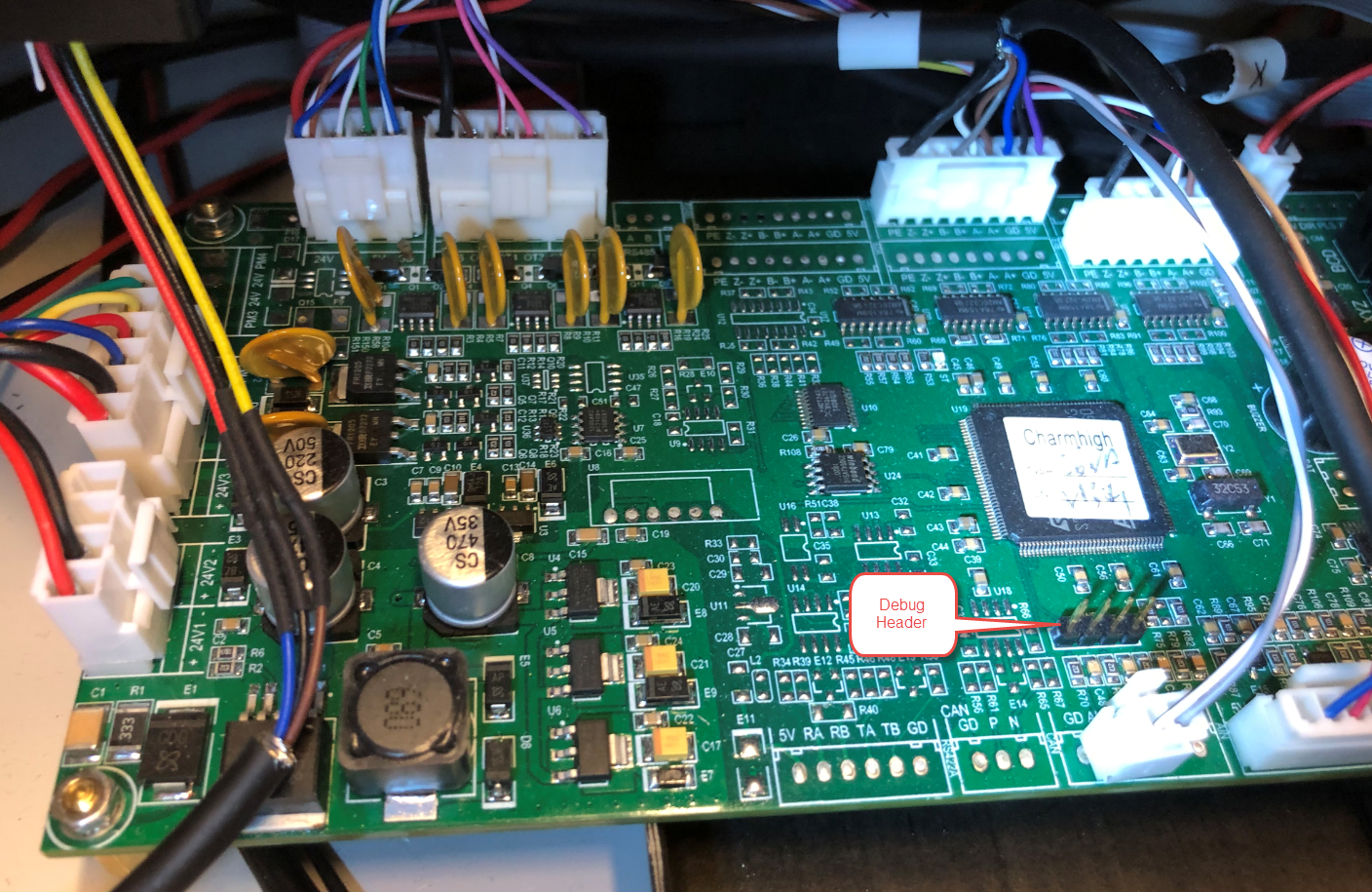
CHM-T36VA Controller Board with Debug Header
Building Smoothieware
Below are the most important steps building Smoothieware on Windows. Detailed information is available on http://smoothieware.org/compiling-smoothie and http://smoothieware.github.io/Webif-pack/documentation/web/html/compiling-smoothie.html
Installation
- Clone https://github.com/mattthebaker/Smoothieware-CHMT into a path without spaces
- Make sure there is no sh.exe in path (check with ‘where sh.exe’ in a command prompt window). I had it in c:\program files\Git, so for running the win_install.cmd in the next step I simply renamed the sh.ex so is not found any more.
- run win_install.cmd from the Explorer windows (double-click on it)
Build
- Double-click with the Explorer on BuildShell.cmd in the Smoothiware directory and execute
make clean - Then do the same with:
make all - The resulting image is in Smoothieware\LPC1768
Flashing
I used a SEGGER J-Link to connect to the target.
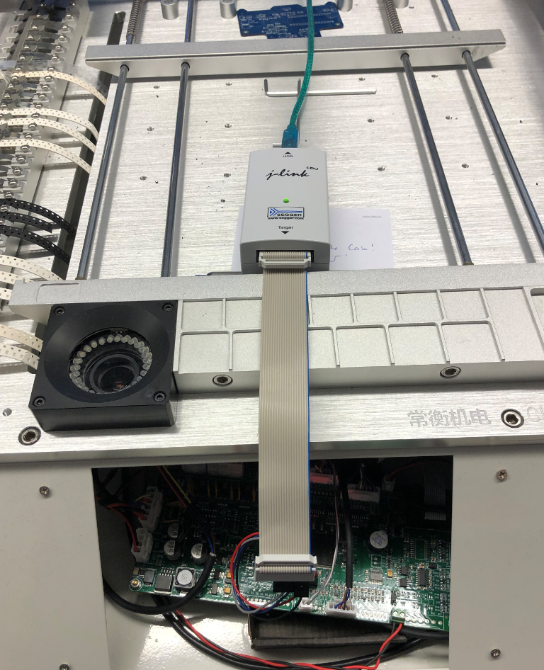
J-Link to flash the controller board
I used jumper wires to make the connection:
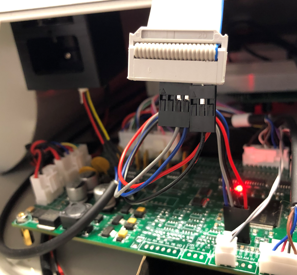
Debug Connection Part 1
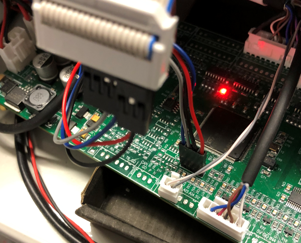
Debug Connection Part 2
Debug Connection Part 3
It is not possible to readout the existing firmware as readout protection is activated:
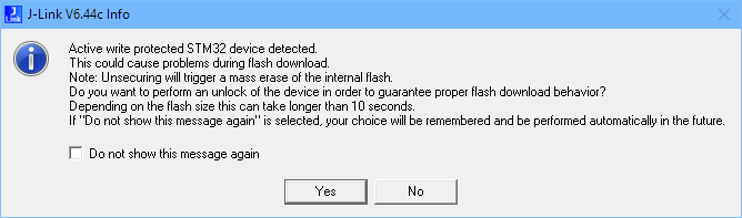
active write protected STM Device detected
Too bad that an article how to bypass readout protection (https://hackaday.com/2020/03/24/breaking-into-a-secure-facility-stm32-flash/) was published after I had erased the firmware.
Using the J-Link FlasherLite was enough to flash the new firmware. The machine will make some strange noise when turning off and on again (don’t worry).
Connect with a terminal/console to the machine and with ‘help’ you should see the Smoothieware respond to it:
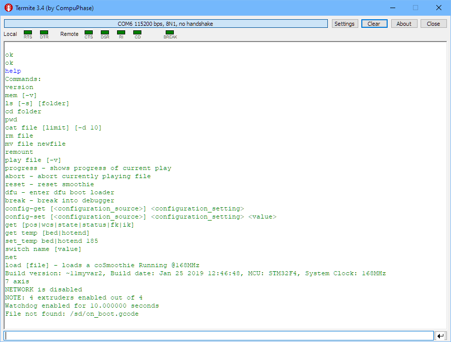
Smoothie on CHMT36VA
Congratulations! The next steps are configuring the machine. I have used OpenPnP V2.
Drag Pin
During machine configuration, I made the mistake to pull down the drag pin for several seconds. The coil only has a resistance of around 8 Ohm and can easily burn the wires if turned on for too long and not released. I had to replace one of the coils:
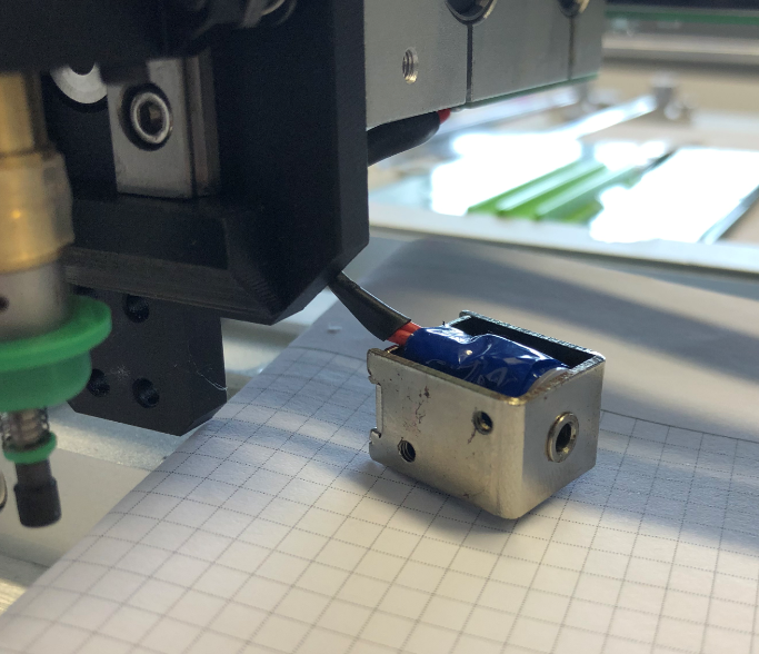
drag Pin Solenoid
I damaged as well one of the drag pins, but luckily the original machine came with one extra drag pin set. I recommend to have some spare parts available, for example I ordered replacement parts from RobotDigg:
Charmhigh drag pin
Drag Feeder
Below a video of the drag feeder in action:
The drag feeder works fine, but as there is only a ‘on-off’ function, the feeder can pull down the needle very hard, causing problems with weaker feeder tapes: the needle can damage the tape holes:
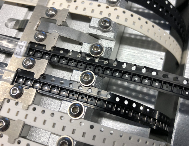
drag feeder hole damage
A trick is to enforce the feeder holes with the tape holes of a paper tape: that way I was able to solve the problem.
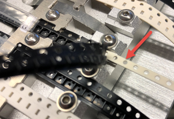
tape hole enforcement
Rotation in Tape
In OpenPnP the correct orientation of parts in the feeder must be configured. The OpenPnP Wiki explains the steps and are shown here as an example.
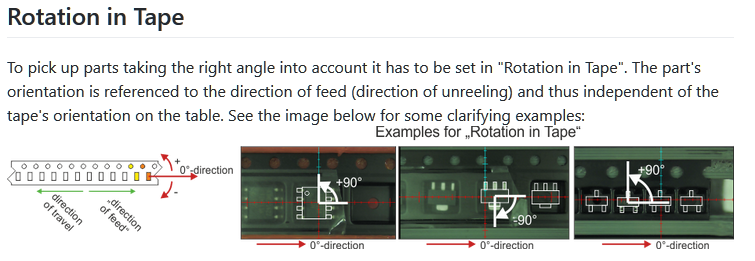
Rotation in Tape
The rotation of the part depends how it is oriented in the layout (e.g. KiCad) program. Below as example the SOT-23:
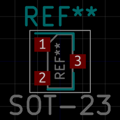
SOT-23 in KiCad
On a PCB it might be placed like this:

SOT-23 Footprint on PCB
In the position file exported and then imported in OpenPnP it shows with a placement position and 0° rotation:
Placement Rotation
In the feeder/tape the part is rotated, so it needs to be configured in the feeder with a (positive) 90° rotation:
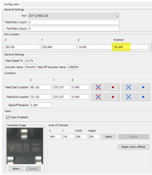
Rotation in Feeder
With this the part will be properly rotated for the placement.
For accurate placement on the CHMT, I recommend turning on ‘Pre-Rotate’ for parts:
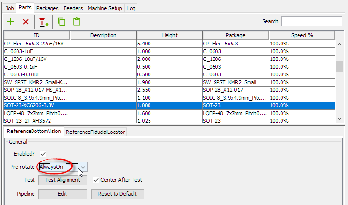
Pre-Rotate Always On
Machine Configuration
The OpenPnP Wiki is a good guidance how to setup the machine. It is pretty much a standard configuration with dual head and dual camera, with the extension of vacuum sensing and air blowing:
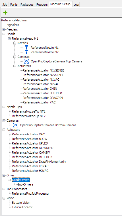
CHMT Configuration Tree
My current machine configuration (OpenPnP V2) can be found on GitHub as a reference, including all packages, parts and scripts: https://github.com/ErichStyger/McuOpenPnP_Machine/tree/master/CHM36VA_OpenPnP/V2
Videos
Below the first but slow board job. The camera was not well tuned, so I used a sheet of paper to shield the lights on the ceiling. With setting camera exposure to lower values this was not an issue anymore.
Video showing the vision system running a job populating WS2812B LEDs:
This shows that the machine is running very well with OpenPnP.
Summary
I do NOT recommend such a conversion if you are not familiar with electronics or if warranty is a concern. A conversion of a machine could be done in a full working day or maybe two, depending on experience with OpenPnP. I did it over the course of two weeks, with some of the tweaking afterwards with the first boards running through production. Most of the time was needed to configure the machine with all the settings, but now everyone else has a good starting point with my configuration on GitHub which should save a lot of time :-).
I’m very happy with the accuracy of the machine: it has populated more than 300 PCBs by now with more +7000 parts on it. It accurately places 0603 parts and e.g. QFN with 0.5 mm pitch. It places around 600-700 parts per hour with bottom camera enabled. Speed is not ‘ultra-fast’ and slower than the original, but speed was not the goal. I wanted a machine I can fully configure and have under control. The other good thing is that the machine is not shaking like crazy as it did with the original firmware.
Another thing to mention about the speed and ‘shaking’: Andreas Axelsson is working on a new firmware:
- Original firmware: https://youtu.be/TvhZLREQ0PU
- New firmware: https://youtu.be/DskvMlGy1-g
New features and improvements coming from the OpenPnP community :-).
Happy Retrofitting 🙂
Links
- machine configuration: https://github.com/ErichStyger/McuOpenPnP_Machine/tree/master/CHM36VA_OpenPnP/V2
- OpenPnP on CHMT36VA: https://github.com/openpnp/openpnp/wiki/CharmHigh-CHMT36VA
- How to modify machine for OpenPnP: https://github.com/openpnp/openpnp/wiki/Charmhigh-modifications-for-OpenPnP
- General Tips&Tricks for using the machine by SparkFun: https://github.com/sparkfunX/Desktop-PickAndPlace-CHMT36VA/tree/master/Tips-And-Tricks
- SparkFun CHMT36VA git repo: https://github.com/sparkfunX/Desktop-PickAndPlace-CHMT36VA
- Matt Baker about running Smoothieware on CHMT: https://github.com/mattthebaker/Smoothieware-CHMT
- Google Forum: https://groups.google.com/forum/#!msg/desktop-pick-and-place/qaoGrnM7pPw/-2k-5FBHCAAJ
- STM32F407 Discovery board: https://www.st.com/en/evaluation-tools/stm32f4discovery.html
- DIY OpenPnP Machine: Building a DIY SMT Pick&Place Machine with OpenPnP and Smoothieboard (NXP LPC1769)

Pingback: “60 Billion Lights”: 2400 RGB LEDs and 120 Stepper Motors hiding behind Canvas Art | MCU on Eclipse
Pingback: Behind the Canvas: Making of “60 Billion Lights” | MCU on Eclipse
Erich, you have did it yet again with an amazing and detailed post! Well done! I am considering doing an OpenPnP conversion of an older Juki PnP that I have. Before I acquired my Juki I considered some of the newer Overseas PnP machines, but found the overall build quality not to my liking and I could see issues with the feeders. The older Juki, etc machines and feeders are extremely well built and the type and quantity of feeders that can be used simply puts the Overseas machines to shame. For example my older juki can have feeders loaded on all four corners with a max (8mm) of 128 feeders. That being said your write up will be very helpful in my efforts and if I do this anytime soon I will certainly post up and also to express my gratitude for your continuous and excellent posts.
Cheers,
Sam
LikeLike
Sam,
thank you! What type of Juki machine are you talking about? The number of feeders sounds impressive. Indded, the number of feeders is a very limiting thing on the Charmhigh machine: it is very complicated to change a reel, so I try to keep the most common parts on the machine anyway. I had a student working on adding new feeders to the machine, but unfortunately this did not work out because of different reasons. I hope someone else might jump on this, or I’ll do it myself.
LikeLike
Good day Erich,
I have a Juki/Zevatech PM575. It is a great machine in that you can load feeders on all four corners. The number of feeders is the maximum and will depend on the feeder widths. For example 12, 16, 24 mm feeders or shaker tubes take up 2 lanes/feeder slots. In my case I load regular (8/12/16/24mm) feeders front and back and have set up the left and right for shaker tubes and SOIC runway feeder styles. The unit was made in the late 90’s and so it is old. The operating system is Dos 6.22 with a Dos Based programming interface (e.g. part setup, feeder pick position, etc). PnP placement data extraction is done directly from my pcb (Altium) using a 3rd party Windows program called Synergy and it works well. The unit is stand alone and weighs approx 450kg and so it is no slouch… it truly is a tank. The gantry moves 2 metres/second and so it is relatively quick using servos. It also has up/down cameras, teach pendant, and a nozzle gantry (I think it can support 8 or 10 different size pickup nozzles). It also uses a interesting 3d laser scanning mechanism to determine and adjust the component placement orientation on the fly and so it can place components relatively quickly (3000 cph or so). The negatives are that the unit is old and the O/S is more than dated. Secondly, the max component height is 6mm… So for larger components you must use something else or hand place which is what I do. Someone on the OpenPnP forum did migrate another similar Juki machine (PM460 I think) to OpenPnP and so I know it can be done.
It is too bad that Juki does not offer a newer model of the PM575, as the build quality of the machine and the feeders is really impressive and if Juki were to offer a high quality newer machine like the PM575 I think it would really sell well for the maker, lower volume assembler.
Cheers,
Sam
LikeLike
Hi Sam, from the pictures I have found on the internet of that machine: impressive and solid machine. The part height is an issue with the CHMT and OpenPnP too: Yes, I populate first the lower height parts, but the machine/software has currently no way to go around already placed parts: so if there a higher part and a new higher parts gets moved over the board, it might hit a part. I ended up populating heigher parts by hand (anyway, usually there are only a few and easy to place manually).
LikeLike
Hi Erich,
Amazing work you have here!
Thanks to this I was able to to the same to my CHMT36VA.
I just have one question regarding the drag pin, I have noticed that OpenPnP doesn’t use the drag pin sensor to know if it got stuck or not, but in the actuator it reads the sensor correctly.
I also checked that the command to read the sensor is M119 but if I send that in the console it doesn’t return the sensor status. This confuses me even more because I have no idea how the actuator is able to read the sensor.
There’s not even a pin defined in the Smothieware to read that sensor…
I wonder if you have the sensor working in production and if so how can I do the same.
Thanks
LikeLike
I was not aware that there is a drag pin sensor (thanks for mentioning it in the OpenPnP group!).
I’m still away from the machine and cannot check the sensor. I have not used that sensor (was not aware of it) and I think I even do not need it:
I never had problems with the drag pin except if I misconfigured the machine.
If the drag pin is stuck for you: maybe you did not do a small retract in the feeder configuration? I pull the tape, then retract a small distance (say 0.1 mm) to get the pin released in a better way.
LikeLike
Hello, great job you’ve done here. I am considering doing the same. With the camera you chose, what is the largest component that you can fit in the frame? With the existing camera the machine can’t see the outline of a 25x18mm part. I know I could adjust the lens but I don’t know if that would cause too much distortion. Maybe you have picked up some larger parts?
LikeLike
Thanks! The largest part I have used is 8×16 mm, and with my setup that was the boundary. the relevant part is the bottom camera. I just have mounted it with the same distance as the previous one: to have a wider angle of view, I would have to mount it say 5-10 mm lower. I have not done this because I want and need a high resolution and narrow view for smaller 0603 0402 parts because there accuracy is important for me, and I have many more of these parts. The larger parts are few and I would be able to place them by hand if necessary.
I hope this helps.
LikeLike
Pingback: New MetaClockClock V3 finished with 60 Clocks | MCU on Eclipse
Great post as usual – how does this machine compare to the DIY machine you had built couple of years back?
LikeLike
thanks :-). It is faster (about 3 times) and much easier to setup/calibrate: the previous machine needed a calibration every time it was turned on. Additionally I have more feeders available.
LikeLike
I don’t get it. Why are people ripping apart a working Pick and Place to end up with the same machine.. that runs much slower for more money… Just because you can? Sure the Charmhigh as issues.. but they don’t go away (like feeder tape retractors). It is finnicky.. but you need to invest less time to get it to work well than you need to rip it apart.
LikeLike
Hi Andrew,
I only can speak for myself: I wanted to use a software/driver which is more user friendly and more powerful to use. If CharmHigh would have allowed to run another external software and open up the protocol, this would be all fine. Jason did some reverse engineering and was close to make it happen, but at the end it was not possible to fully control the machine. To bad.
The feeder tape retraction is a problem, so we solved that with our own custom feeders which only would have been possible with OpenPnP.
So yes, it was about the CharmHigh issues and mainly because of their program on the host. Oh: the memory stick from CharmHigh was infected with a virus too, they even did not bother when I told them.
If you have a machine and it works perfectly for you and you are happy with it: no need to change anything, of course. To me the hardware is decent for the price compared with other machines, but their software was not. That’s why I wanted to run it with OpenPnP.
PS: You can change the speed of the machine, and it would run about the same speed as with the original firmware, but it shakes so hard making it unusable (as with the original firmware). So I reduced the speed to about half of the original one so it works reliable. There has been efforts in the open source community for a new motion algo (but did not follow that much).
LikeLike
Hi Eric, I was wondering how you configured the peeling action in OpenPNP to run peeler after each pick?
LikeLiked by 1 person
See the LFEEDER definition in the machine.xml which is triggered by the ReferenceDragFeeder.
LikeLike
Cheers for the writeup! I just followed through this myself and everything works well.
A few notes from my build that might help others:
– There’s two types of semi-open drag chains. Open inside and open outside. I got the open outside ones, so when you lay them on the tracks, the open segments are sitting on the rail (so you have to put the cables in first), as opposed to the open inside ones you have where you could lay the chain then put the cables in. Still works, just a little fiddly and something to note when ordering. Although this is tricky as I thought I ordered the same ones as you, but I got sent these anyway. You might also have to drill new holes in the chain ends for mounting. Just use the old ones as a guide.
– When building smoothieware, if there’s a space in the directory it breaks the build scripts. Place it in a root directory somewhere for easy building.
– Smoothie builds for the STM32F407xG, but the STM chip on the CHMT36VA is STM32F407xE (specifically the STM32F407ZE). The build still works fine as the only difference is flash size and the build is well below the total flash requirements. The resulting image is in STM32F407xG/main.hex
– Some USB hubs and ports on PCs can’t handle both cameras at once (I installed a hub inside the machine and a chassis mount connector for one USB port for the whole machine). So if you can’t get both cameras working, try different ports/hubs and possibly a powered hub. When installing a hub inside, you don’t need extra USB cables, as the cable lengths of the new cameras are plenty.
– It programs just fine with the J-link EDU as well. Here’s a good pinout guide for JTAG/JLINK – https://www.segger.com/products/debug-probes/j-link/technology/interface-description/
– Here is the header pinout for the CHMT – https://raw.githubusercontent.com/c-riegel/misc/master/IMAG1221-20190916-141902825.jpg (from here – https://github.com/openpnp/openpnp/wiki/Charmhigh-modifications-for-OpenPnP)
– You might have to re-specify the camera device in openpnp as they seem to slightly change compared to what’s in this guide’s machine.xml. Also be sure to change the serial port under driver>gcode drivers.
– There’s two cameras in this machine.xml, one is under Cameras and the other is under Heads>ReferenceHead H1>Cameras.
– The top down camera focus ring (accessible after you unscrew the end cap on the camera) has to be turned quite a few times before it goes into focus.
– The bottom up camera has a small philips screw for orientating the lens. Loosen it and center align it with the cutout in the camera housing, then the two top focus screws can be placed such that their center point aligns with this screw for easy focusing. There are two holes for the top focus ring (nearest the lens), you can move it to another hole to have it fit better in the housing.
– There is a PR for the drag pin sensor that is not yet pulled into Matt’s repo, you might want this to be able to detect a stuck pin in tapes – https://github.com/mattthebaker/Smoothieware-CHMT/pull/6
All in all a fun build I’ve been putting off for a while. The machine certainly feels a lot better now under openpnp and with the new cameras.
To anyone thinking about this, do it and be gone with that god awful firmware!
LikeLiked by 1 person
Thanks for putting up all the details for everyone else out here, appreciated!
LikeLike
Setup for the pin detector is here – https://github.com/mattthebaker/Smoothieware-CHMT/issues/4#issuecomment-791372779
LikeLiked by 1 person
And note that the M119 command output has changed format due to the additional change in that PR (“Bugfix: There is no max endstop on Z axis.”):
X_min:0 Y_min:0 Z_min:1 pins- (X)P4.4:0 (Y)P4.3:0 (Z)P2.13:1
LikeLike
Thank you for that link! Reminds me that I should upgrade my machine configuration.
LikeLike
Just wanted to add another tip for obtaining the xy offsets for the drag pin as there doesn’t seem to be a documented way to do it yet (there might be but I hadn’t found it).
Similar to the offset wizard for the nozzles, place a thin piece of blutack on a blank PCB in the holder. Move the pin over the blutack and actuate it momentarily. Now jog the top-down camera towards the mark in the blutack and count the steps you’ve taken until it’s centered. Bam offset values!
Would be good to have this as a wizard at some point. I might look at creating a “DragFeederActuator” implementation at some point to do this and PR it.
LikeLiked by 1 person
Thank you, that’s a very good tip! I have used a piece of clay for this. The same trick is described in the OpenPnP documentation for setting the offset between down-looking camera and picking nozzle.
LikeLike
And another tip. Be sure to leave a little cable length for the down facing camera, so the head cover fits back on. Cable tie the wires back in the head and do a test fit before routing through the drag chain.
LikeLiked by 1 person
Here’s some more pics of the guts of the machine – http://imgur.com/a/zvnK3sk
LikeLiked by 1 person
Great job Erich, I do have a question re the uplooking camera. I thought I had ordered the same camera as you, but what I received has a much smaller lens and limited focus. The part number on the back of the circuit is; ELP-USBGS720P02-L100. Do you have the specific part number for your camera? Thanks Wayne
LikeLiked by 1 person
Hi Wayne,
I had mine from the ‘ELP Camera Module Factory Store’ on AliExpress, the one with the 2.8-12mm lens. Here is the link to it (not sure if it will work in the future): https://www.aliexpress.com/item/33015394467.html?spm=a2g0s.9042311.0.0.27424c4dSlBN1D
It is not easy for me to find the part number on the camera: I would have to disassemble the machine, and the machine is used in the lab right now.
I hope this helps,
Erich
LikeLike
Thanks Erich,
Turns out you can just swap the Lens from the 36VA to the ELP as they both are 12mm mount type 🙂
LikeLiked by 1 person
Ah, that’s great!
LikeLike
Pingback: DIY Split-Flap Display | MCU on Eclipse
Hi, I do small scale pcb pnp with a chm-t36va. I was wondering if it is worth it to do this conversion? What are your guys thoughts after using openpnp for a while?
LikeLiked by 1 person
I never wanted to go back to the original Chinese firmware: it is like day and night. One thing to consider: the original firmware is faster, but the machine shakes like crazy. With the Smoothie OpenPnP firmware the speed is somewhat lower, but I can have the machine working on a normal table without fearing that it shakes off parts from the feeders or board.
LikeLike
yeah, speed is not a issue to me, it gives me more time to solder paste the next boards. Thank you very much.
LikeLiked by 1 person
Yes, same for me 🙂
LikeLike
Hi, ive been trying to copy over your machine setup files into my openpnp software, but whenever i try and launch openpnp it gives a error message saying that the input file can’t be read. Is it possible to do this? or am i missing something?
LikeLiked by 1 person
It could be that you are using a newer version of OpenPnP? I that case it could be that the file content is not compatible.
LikeLike
How well does the drag feeder works for you? I have a similar machine (TVM802) and it work maybe in 50% of cases. This was the original China-PnP. Will see after conversion to OpenPNP.
LikeLike
It works very well for feeding parts ‘paper’/’cardbox’ tapes (resistors, capacitors, …). I had sometimes issues with ‘thin plastic’ tapes (some LEDs or transistor use that) when the drag pin was pushing out the drag holes on the tape. I solved that with carefully balance the pulling power with the tape counter ‘weight’. Other than that, the drag feeder has been working very, very well for me.
LikeLike
Pingback: CHM-T36VA Pick N' Place Machine - The Personal Blog Of Steven L. Rhine
I purchased a Charmhigh CHMT48VB in early June 2024. After months of effort I was able to mostly get a usable board off of the system. There is another organization in town (Tucson, Arizona) that has the same system and their experience was similar to mine. To save the next person a lot of time, I have published a detailed review:
– https://www.hdssystems.com/Articles/CharmhighCHMT48VBReview.pdf
and DPV file format specification:
– https://www.hdssystems.com/Articles/DpvFileFormat.pdf
and a spreadsheet for generating the DPV file needed to drive the system:
– https://www.hdssystems.com/Articles/ExampleDpvSpreadsheet.ods (LibreOffice format).
Charmhigh stopped responding to e-mails as soon as the machine was delivered – so don’t expect any customer support or warranty support if you buy their system.
My experience with Charmhigh suggests they are a less than honorable company and I suspect they intentionally crushed the OpenPnP project because they did not want the competition – or the bad press.
With the system I have, it was necessary to slow the tape drag pin speed in order to get things to work most of the time – see details in the review. Fast drag speeds result in parts bouncing out of the pocket or other related issues.
I also dropped the head speed to reduce table shake. This also reduced the number of dropped parts and parts that moved after they were placed. So even though OpenPNP may be slower than the default settings, by the time you slow things down to make them work more reliably, I am guessing that OpenPNP will be of similar speed.
I considered upgrading to OpenPnP but it appeared to me the project was no longer active. Then there was the large (huge) effort to get things upgraded and running using tools I am not familiar with. I saw one review of the upgrade process and noted the person having to build special connectors because Charmhigh had purposely miss-wired connectors to make it hard to access programming ports.
Just my 2 cents. Your milage will vary.
LikeLike
Hi Henry,
thanks a lot for your detailed report. I had a similar experience with Charmhigh, and others as well. It seems they just want to sell their machines and not supporting it. OpenPnP imho is still active, but as my current machine is running well, I hesitated to upgrade to newer versions.
LikeLike
OpenPnp is definetly still active.
I upgraded to Smoothie about 3 years ago and use OpenPnP on a weekly basis, it was 100% worth the effort.
LikeLike
Same for me. 5 years ago I upgraded the machine with the Smoothieboard, and it has been worked flawlessly. I never considered going back, and OpenPnP worked great after learned how to work with the vision pipeline.
LikeLike