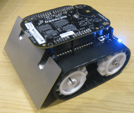
The cool thing with the Freedom board is: there are many exciting Arduino boards out there which want to be used with the FRDM-KL25Z. I have spent most of my last week-end with creating a little black beauty:
When I was looking for some nice DC motors with quadrature encoders for my next lecture project, I stumbled over the Pololu web site which had *exactly* the DC motors I was looking for. And their Zumo Robot Robot Kit was something which attracted my eyes.
I always joked 🙄 about women shopping habits. But my wife is right: If it is about electronics, I’m not different at all 😀
That robot is smaller than 10 cm on each size, so it qualifies as a Mini-Sumo. Although I have a different purpose in mind for my robot…..
Chassis and Motors
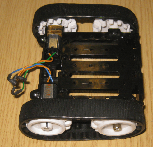
I ordered the chassis with two 75:1 Micro High Performance Metal Gearmotors which enable the chassis to move about 50 cm in a second. The chassis includes a battery compartement on the bottom for 4 AA batteries (so up to 6V):
💡 I did *not* follow the Pololu instructions to solder the motor with the Arduino shield: instead I used flexible wires to attach the motors to the board. That allows me to change motors or disassemble the kit in a much simpler way.
Arduino Board
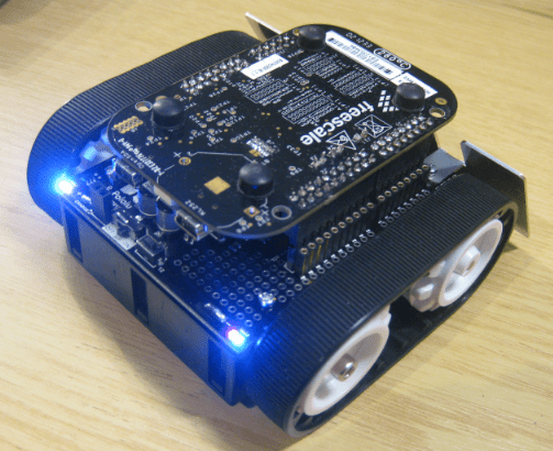
The Arduino board comes with a few parts unpopulated (Buzzer, Headers, Switches). The board features a tiny (but powerful) Dual Full-H Bridge, a Buzzer, Battery Voltage Sensing and a I2C Accelerometer+Magnetometer sensor:
Freedom Board
The FRDM-KL25Z needs to connected ‘face down’ to the Zumo board. I plan to layout an intermediate PCB with my to-be-added hardware. But for now I’m using normal breakable header rows as ‘interconnection’. This is necessary as otherwise the Freedom board is very close to the Zumo board components:
Power Supply
The FRDM-KL25Z is powered from the batteries through P5-9V_IN. But: the Freedom board only generates the 3.3V from P5-9V_IN, and but not the needed 5V to the header (see this post). That 5V is needed by the Shield. So for now I’m using a rather bulky DC-DC converter and supply the needed 5V from the battery to the USB 5V supply line, until I can replace the DC-DC converter with a smaller one. At least everything is working now :-).
Software, and Next Steps
The software in CodeWarrior with Processor Expert is ready for most parts. Motors (speed/direction), LED’s and Buzzer are working. Magnetometer/Accelerometer and Battery Voltage Sensing are in progress. The current software is available on GitHub with all the Processor Expert components. And: I have a Bluetooth module ready to integrate, plus I want to add a line scanning module too. So enough fun for a couple of dark nights and week-ends :-).
Happy Zumoing 🙂


Pingback: The Freedom Zumo Robot « Patoid's Blog
HOT DOG!!! Way to go Erich!
I might build one myself, just because…
😉
LikeLike
Pingback: P201301 로봇 프로젝트를 위한 로봇 몸체 구매 « devstark
Pingback: Zumo Line Following with FRDM-KL25Z | MCU on Eclipse
Pingback: Bluetooth with the Freedom Board | MCU on Eclipse
Pingback: Freedom Robot solves the Maze | MCU on Eclipse
Pingback: FRDM-KL25Z RevE Board arrived | MCU on Eclipse
Pingback: Mini Sumo Robot Competition running with FRDM-KL25Z | MCU on Eclipse
Hi, Erich.
How do you control the robot?
LikeLike
Hi Alex,
the one in this post is controlled by a FRDM-KL25Z (ARM Cortex-M0+). But no wireless controller.
Have a look at the ones in these posts:
They can be controlled with Bluetooth, IEEE802.15.4 or with an nRF24LP+
LikeLike
I think i will go with the nRF24LP+.
Thank You.
Alex
LikeLike
I like what you did with the motor leads. I want to be able to switch out the motors too.
LikeLike
Erich,
Looks like you soldered the battery terminal tabs to the sumo shield. Does that mean you cannot remove the shield from the chassis? Or did you rig it so that you can? I want to be able to switch motors out as needed so I need to figure a non-permanent way to attach the terminals.
LikeLike
You can remove the shield with the battery terminals soldered to it, it is designed that way. Because the chassis has large holes for the battery terminal taps so you can pull it out of the chassis. You just will need to pull in the spring of the negative terminal e.g. with a flat screw driver.
LikeLike
Ah, I was over thinking it. I noticed that the positive terminal slipped through but I didn’t think to simply compress the spring on the other. Thanks for that. Saved me some time and trouble.
I’m going to build mine with the optical encoders from Pololu that attach to the extended motor shafts. Not happy about all the wires involved (6 per motor).
LikeLike
Yes, I’m tinkering about using these optical decoders mounted on the extended shaft too. As Pololu states, it is not very easy to use them, definitely not recommended for an electronics beginner. One critical point is to place them in the correct distance to the motor. The other thing is that the signal needs some post processing/amplifier. I’m looking into different options to make this easier. I wish Pololu would provide a solution on this. Until then, I probably build my own 🙂
LikeLike
Yikes. I didn’t realize about post-processing. I guess that gives me a pure electronics project to look into. I thought the encoders where very inexpensive and now I understand why.
I have Pololu’s other encoders on a different setup. I just got them installed and will program it shortly. I’m thinking I’ll need to use one of the many mini RTOS kernels for my Arduino to effectively process the inputs while still being able to perform other logic.
Regards,
Tom.
LikeLike
Yes, the other Pololu encoders give you a digital signal. You need to add electronics to these small shaft mounted encoders like what is done on the Pololu wheel encoders (I used as well for the Zumos). These encoders are rather expensive because of the added electronics. What you need is an adjustable amplifier with digital signal generation. I’m thinking about using an I2C based D/A converter with an amplifier so I can avoid to add trimming potentiometers: that way I can automatically (hopefully) transform the analog sinus-like signals into good digital quadrature signals.
LikeLike
Just to let you know, the optical encoders worked without any post processing of the analog signals. At least they work with full batteries. Maybe as the battery level drops then the signals will too?
I can’t get over their resolution. 1200 ticks per revolution using the three tooth wheels. Just crazy.
My Zumo is nearly working. Just having issues getting the motors and front servo to turn at the same time. 🙂
LikeLike
Are the encoders working reliably? Yes, you will get a signal if the sinus is high and low enough on the digital pins. But it will not be a nice signal, and not something for high speed. I’m working on a circuit with amplifier and rectifer. The prototype works now (after one iteration), and a new PCB should arrive next week. With this I can auto-calibrate the signals. I guess I need to write a post about it once I find time.
LikeLike
It looks solid for now but time will only tell. I’m guessing as the battery power drops so will the signal. I’ll take a capture to see what they look like then.
I did notice that at certain stationary positions the tick count will oscillate back and forth by 1. Obviously the signal is just at the high/low threshold.
Please post about the amplifier circuit. I’d be very interested in learning more.
All the best
LikeLike
I saw the signals in your post, and while you feel they are looking good, I think I cannot agree: did you make that scope picture with high speed? if you have not clean rectangle signals, it will be very hard to correctly measure the signals, especially at higher speed.
LikeLike
No that is true, it was not at a high speed. I was just happy it worked at all. Ever the optimist when it suits me 🙂
Right now the encoders are the least of my worries. I’m finding it nearly possible to control both the motors and a servo at the same time on the arduino. The ATmega328 seems limited in this regard.
But this is all new to me so I need to dig deeper to figure out what the real limitations are. Maybe the libraries I’m using are the problem. Need to go directly to the ATmel data sheets and learn how things work exactly. Just might be wasting my time with the arduino uno platform. I do like its simplicity though….
LikeLike
Forgive me my comment on Arduino: they are a great thing to start with, but not suitable for this kind of things where realtime aspects get key. I have seen so many students starting their projects with an Arduino board. And while they have something up very quickly, they fail to the end because they run into these kind of problems. It is not the problem of the ATmega, it is a problem of the Arduino drivers: most of them are in polling mode only. Again: they are a great way for a quick and ‘dirty’ small project. But not for something more complex (and your project gets into the ‘complex’ domain). Same applies to the mbed world too, btw. The key is to select the right methodology and tools for the problem you try to solve. My usual quote on this is: “Arduino/mbed kind of things is like Fast Food: they are a reasonable thing for a quick and cheap meal. But you do not want to have it all your life (for health reasons too ;-)). For your real engineering life you need either cook your own meal, or pay for it in a good restaurant.” In essence, in my classes I could have selected the way to teach/use mbed/Arduino: that would have worked to some point to solve simple problems, but not for the harder problems an engineer has to solve (and I have the challenge to build up engineers). Again: mbed and arduino is a great thing to teach programming to kids, artists and at the beginning. It is just like with Mc Donald’s: there is a time where you do not want that ‘Happy Meal’ any more ;-).
LikeLike
Regardless of the signals, I’ve discovered that the resolution of the encoders is too demanding for a 16MHz ATmega328, as the timings for all other systems are being affected by the excessive interrupt-level loading.
I’ll explore more but I thinking it’s back to the drawing board for now…
LikeLike
I calculated a needed sampling period of around 20 micro seconds. That’s doable for my ARM Cortex-M0+, but I agree that this ATmega will not do it: it has simply not enough processing power. I was considering to add a small ARM microcontroller just in charge of the encoding: they do not cost much, and make things a lot simpler. It would communicate with I2C with the rest of the system.
LikeLike
Great project and excellent post!
A question about the motors: Did you use 0.1 uF ceramic capacitors across the motor terminals as advised by Pololu, or didn’t need them?
LikeLike
Yes, I have put 0.1 uF ceramic capacitors over the motor terminals. That greatly reduces the noise. For our own PCB’s built on that chassis (https://mcuoneclipse.com/2013/10/06/zumo-robot-assembled/) we have put large additional capacitors on the board too.
LikeLike
Pingback: New Zumo Robot PCB’s Arrived! | MCU on Eclipse
Pingback: O que é um microcontrolador e o que eu faço com isso? | void Hardwarizando( ) {
Pingback: Zumo Robots at Maker Faire in Rome (16. – 18. Oct. 2015) | MCU on Eclipse
And here nother minisumo robot project: http://jsumo.com/sinan-pasa-mini-sumo-robot-series-version-1-2-3/ 🙂 Please look;)
LikeLike
that’s a really cool Sumbot, indeed! And it has a a really interesting mechanical design. Thanks for sharing 🙂
LikeLike
Can i use Arduino Motor Shield instead of using Zumo motor shield as it is not available in india!
Or is there any other way to implement a line follower bot using the FRDMKL25Z and IR Sensor ?
LikeLike
Yes, you can use any motor shield with a IR sensor to implement a line follower robot.
LikeLike
So how do i connect the FRDM with motor shield?
LikeLike
You need to connect the PWM lines to the motor PWM inputs.
LikeLike
One more question
If i am planning for more operations like obstacle avoiding which is the Ultrasonic sensor should i use for this?
LikeLike
I’m using the HC-SR04 (see https://mcuoneclipse.com/2013/01/01/tutorial-ultrasonic-ranging-with-the-freedom-board/). But I do not really recommend ultrasonic sensors for this, they are not very reliable. Better us ToF sensors, see https://mcuoneclipse.com/tag/tof/
LikeLike
Thanku
Will try getting the same sensor!
LikeLike
Perhaps a simple question. I assume you haven’t removed the ATMega, and you could still use it if you removed the FRDM board? How do you work around the ATMega? Is it as simple as leaving a blank image on the ATMega?
LikeLike
That Pololu Zumo board does not have any ATMega on it. That board has been originally designed to place an Arduino board on top of it, similar what I did with the FRDM-KL25Z board.
LikeLike
That’s annoying. I’ve bought the Zumo 32U4 Robot when I should have bought the Zumo Robot for Arduino. Looks like I’m up for a new shield.
LikeLike
Yes, the 32U4 has a microcontroller alreay on it. I guess Pololu was inspired by my version of the robot where I have put the NXP/Freescale Kinetis K22 directly on the base board, and then came up with the 32U4 design. 🙂
LikeLike
I found your blog while I was trying to work out plans for building my Zumo. Could describe a little more about how you attached the wires to your motors and shield? As I understand it, the motor wires are soldered to the shield, but have a solderless connection to the motors. How did you do that?
I’m particularly interested in solderless connections because I am interested in switching components in and out and experimenting with different configurations.
Thanks,
Jack Foust
LikeLike
Instead of soldering the wires directly to the board, I used normal pin headers plus heat tubing to isoloate it. So soldered a pin of a 2.54mm header to the board, and soldered the connector the wire, and put heat shrinkage tubing around it. Nothing special at all (I think).
I hope this helps,
Erich
LikeLike