
The year 2022 is coming to an end, and I have spent some time today on a little side project. It is about making an Electrical Vehicle (EV) wallbox charger accessible over Modbus RTU. It is not finished yet, and I plan to publish more articles on it, but I can share that I’m able to access and control the Heidelberg EV charger with a Raspberry Pi Pico W (Dual Core Cortex M0+), NXP K22FN512 (Cortex M4F) and LPC845 (Single Core Cortex M0+):

Outline
With the war in Europe, energy prices are at a record high (see Energy Crisis in Europe: Optimizing a Building). Gasoline prices in Switzerland were up to CHF 2.25/liter in June 2022, and dropped now to around 2.00 CHF. While electricity pricing is still very high (up to CHF 0.8/kWh), it makes sense to consider having an EV car, especially with a self-production costs of about CHF 0.15/kWh. We don’t have an EV car yet (the current is a hybrid one), but this is something scheduled for early/mid 2023. To prepare for that arrival, and in the light of silicon shortage, I ordered the charger already this month. With the benefit I can play with it in advance during the holidays :-).
In this article, I’ll show how to get the Modbus interface up and running for the Heidelberg EV charger. For this I re-used existing boards I have used with RS-485 plus a Raspberry Pi Pico W, with the plan to add a display on a custom PCB in a future step.
Heidelberg Energy Control
I considered several different charger and wallbox solutions, able to charge up to 11 kW AC. For a 11 kW charger, I only have to notify the grid provider. If there is no technical reason against the installation, they approve it. Installing and getting a 22 kW wallbox is much more complicated, so I decided for the 11 kW version (3-phase) with a Type 2 1-3 phase connector.
I selected the Heidelberg ‘Energy Control’ EV charger because:
- Included fixed charger cable (5 meter) (others do not include that or come with a separate plug)
- Stainless steel enclosure (more robust than a plastic enclosure)
- Very Low standby of 1 Watt (others consume around 6 Watt)
- One-phase (230 V), two and three-phase (400 V)
- Adjustable 6 to 16 A (11 kW) charging current
- External key connector (sometimes a requirement from the grid provider they can control the unit)
- Residual DC 6 mA current detection (IEC62955) (others do not include this and a dedicated DC one is very expensive)
- Modbus RTU interface (others do have WiFi, or not many have an open interface)
The charger is made in Germany and is really well engineered and documented. The electronic parts are inside a robust IP54 enclosure, with a window for the status LEDs:
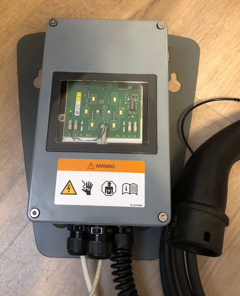
The LEDs shine through the front and are used as status indication. It would be possible to replace that front inlay with a custom one.

The very low standby Wattage and the Modbus interface were key to me. Unlike other chargers, it does not have a WiFi interface, which to me is a good thing: Less standby current, and that way there is no real need for a firmware update (which is frequently needed for WiFi based devices). Plus I always prefer a wired interface if possible: I can add a wireless connection with a Raspberry Pi Pico W or ESP32 under my control.
The charger is able to do load-balancing for up to 16 chargers: simply chain the Modbus interface and set some jumpers. What I really wanted, is to integrate the charger into my home energy management system (HEMS with HomeAssistant). For this the Modbus (RS-485) interface is key: with this, I can adjust and control charging based on the energy coming from the PV (photovoltaic) system, optimizing solar energy usage: ideally, no grid electricity is used for charging the car, because the system follows the solar production.
Modbus Wiring and Jumper Settings
For the Modbus wiring, I used a CAT5e (twisted pair Ethernet cable, shielded). Only one pair (the blue one) is used, with the cable shield connected to the chassis ground using a zip-tie.
Note that the picture below shows a 1-phase AC wiring for Modbus test, and not the final 11kW 3-phase one.

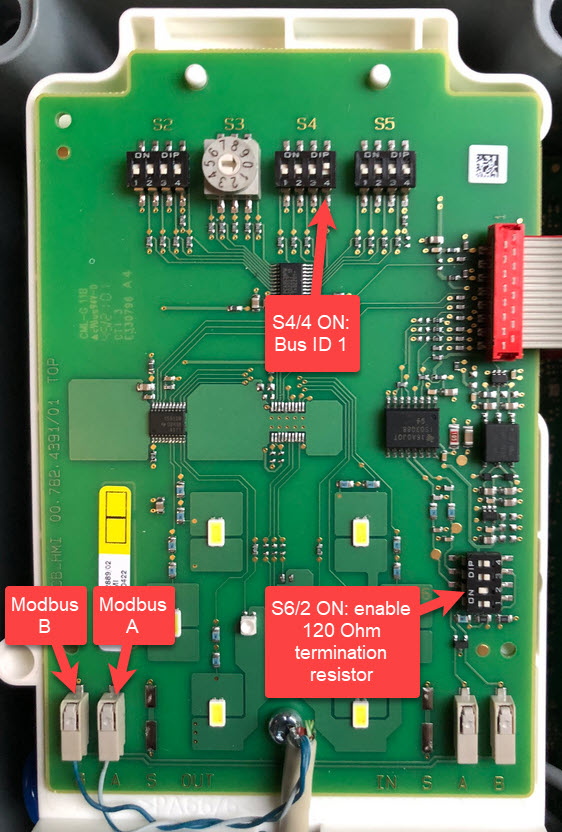
The green PCB on top implements the status LEDs, most of the jumper/switches plus the Modbus/RS-485 interlace. With that PCB elevated and away from the high power base PCB, noise or EMI is greatly reduced. The shielding of the cable is connected to the chassis ground.
On the lower left there is the 1-3 phase power input, with the power output connection on the lower right.
The Modbus/RS-485 cable from the master needs to go to the left OUT (the label on PCB is clearly wrong, as the resistors of the bus are on the right side (IN)) connector on the left side. The switches for S2 and S5 all needs to be off, only two switches need to be turned on:
- S4/4 on to assign Modbus ID 0x1
- S6/2 on to enable the 120 Ohm termination resistor on the other (In!!!) side.
Checking Modbus connection
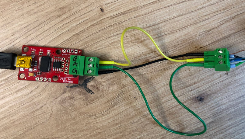
My previous experience and tools from working with RS-485 came in handy, for example that SparkFun RS-485 to USB adapter:
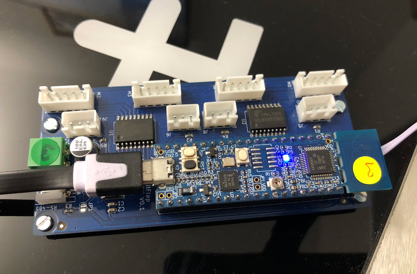
The same way I was able to re-use the RS-485 circuit used for the Split-Flap project using a NXP K22FN512:
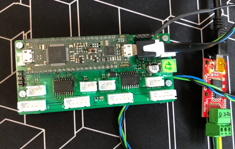
The software runs on a LPC845 too:
The firmware using the WiFi on the Raspberry Pi Pico W is work in progress: The WiFi user interface is not working yet:

Settings need to be as below for the Modbus connection to the charger:
- Baud: 19200
- Data Bits: 8
- Stop Bits: 1
- Parity: even
A good tool to check a working ModBus RS-485 connection is using QModBus.

Reading from input register 4 on device/slave ID should return the value 264, as noted in the manual:
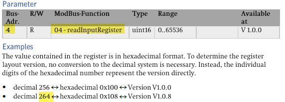
It is is necessary to periodically poll the wallbox, otherwise it enters an communication error state by default. This can be changed by software (see below).
Software
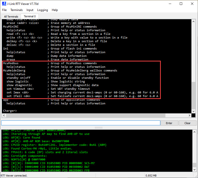
The software is written in C and integrates with FreeRTOS. It is part of the McuLib on GitHub:

The McuHeidelberg module implements the Modbus functionality for the firmware Heidelberg firmware V1.8.
The command line shell interface supports SEGGER RTT, UART or USB CDC.
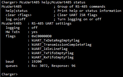
The McuUart485 provides additional settings and logging for the connection:
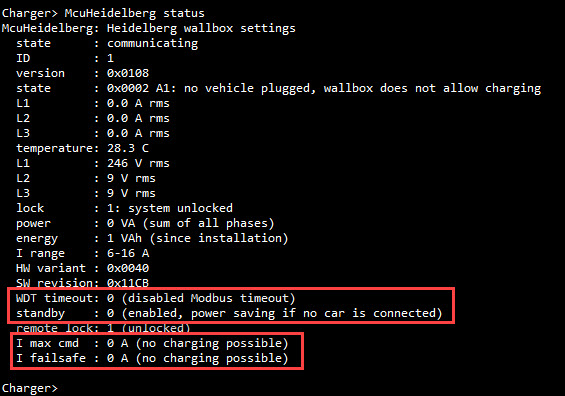
A dedicated Modbus task communicates with the EV charger. It reacts on status changes (e.g. vehicle connected and ready to charge). All the box settings can be configured through the command line interface and settings are shown with the ‘status command’, for example:
McuHeidelberg: Heidelberg wallbox settings
  state      : active
  ID         : 1
  version    : 0x0108
  state      : 0x0002 A1: no vehicle plugged, wallbox does not allow charging
  L1         : 0.0 A rms
  L2         : 0.0 A rms
  L3         : 0.0 A rms
  temperature: 26.8 C
  L1         : 240 V rms
  L2         : 0 V rms
  L3         : 0 V rms
  lock       : 1: system unlocked
  power      : 0 VA (sum of all phases)
  energy     : 1 VAh (since installation)
  I range    : 6-16 A
  HW variant : 0x0040
  SW revision: 0x11CB
  WDT timeout: 0 (disabled Modbus timeout)
  standby    : 4 (disabled)
  remote lock: 1 (unlocked)
  I max cmd  : 0 A (no charging possible)
  I failsafe : 6.0 A
With no vehicle connected yet, I have not tested everything, but things are looking good so far.
Low Power
Few might consider the standby power of a wallbox, and that value is usually hard to find in the data sheets. I currently plan to add a dedicated circuit breaker nearby so I can completely cut it off to let it consume 0 Watt. I have measured the box, connected to a single phase. WDT timeout is disabled, with standby enabled and charging current set to zero, with no vehicle connected.
By default, the box enters a standby mode after 3 minutes if no vehicle is attached, which is configured with register 258 (Standby Function Control). Second there is a timeout value for the Modbus (register 257, WatchDog Timeout), after which the box will detect a communication timeout. I have disabled that timeout. With the current max (register 261) I configure the charging current (0, as no vehicle connected) and failsafe current (register 262) I tell the box what to do if Modbux communication fails.
So let’s see what this means for the standby power consumption of the wallbox.
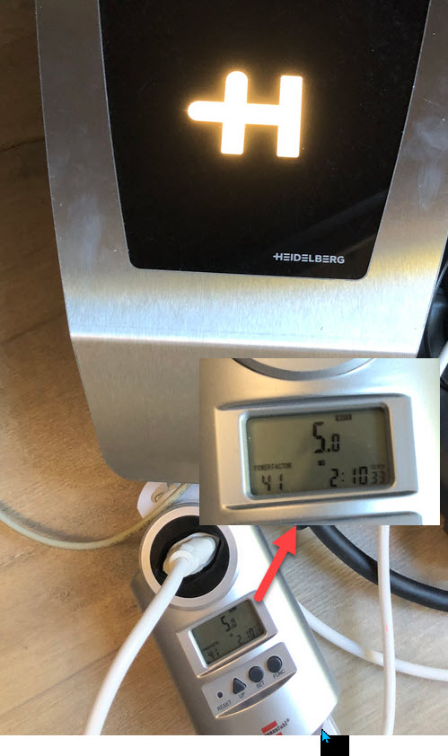
After power-on, with the LEDs turned on, it consumes 5 Watt:
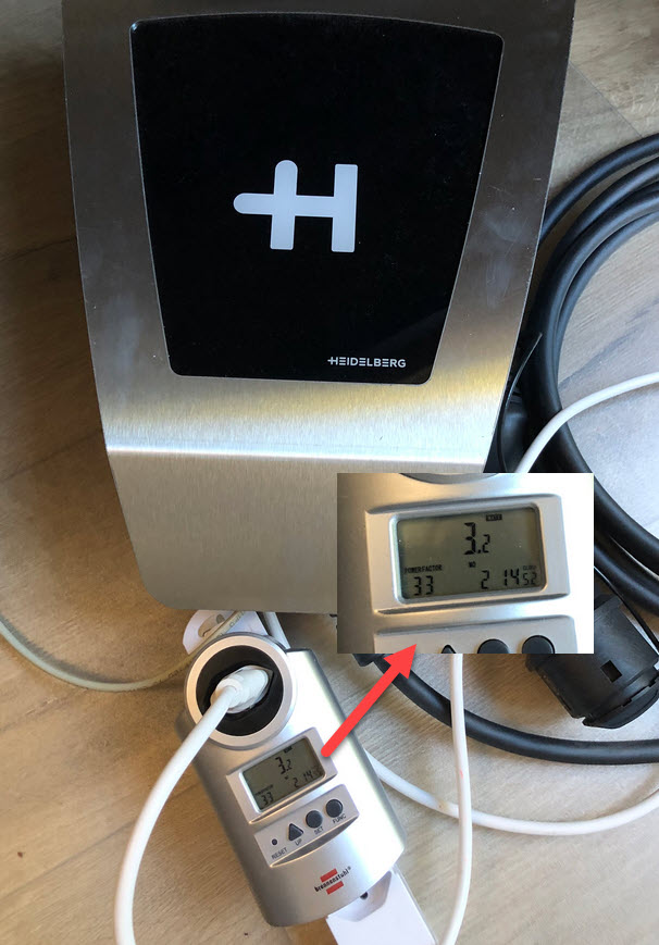
After 5 minutes it turns off the LED, and it goes down to 3.2 W:
After 5 more minutes it goes into a deeper standby, consuming only 1 Watt:
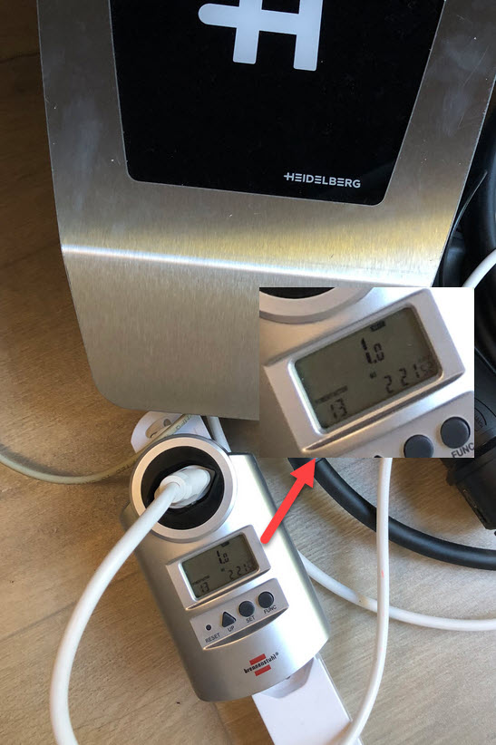
I plan for a circuit breaker/switch to completely turn of the wallbox to get rid of that 1 Watt too.
Summary
I love that Modbus interface to that Heidelberg EV charger: It gives me full control and the possibility to maximize solar energy usage. The Modbus library and code works very well. So far I have a command line interface working, running on a NXP LPC845, NXP K22FN512 and a Raspberry Pi Pico W. The Pico W will give me a WiFi interface. Additionally I plan to design a dedicated PCB, having a small OLED and some buttons as a user interface. The full integration into HomeAssistant is pending too. So plenty of things for some follow-up articles 😉
Happy charging 🙂
Links
- Software on GitHub: https://github.com/ErichStyger/McuOnEclipseLibrary
- Heidelberg: https://www.amperfied.de
- Modbus: https://en.wikipedia.org/wiki/Modbus
- Sparkfun RS-485 adapter: https://www.sparkfun.com/products/9822
- QModBus application: https://sourceforge.net/projects/qmodbus/
- Another project with the wallbox: https://www.amperfied.de/de/clever-laden/blog/wbec-fuer-heidelberg-wallbox-energy-control-blog/
- Useful discussion about this wallbox: https://github.com/ioBroker/AdapterRequests/issues/559

Happy New Year, Erich
LikeLike
Thank you, and Happy New Year too!
LikeLike
Pingback: Erich Styger's Modbus RTU Project Connects Microcontrollers to Electric Vehicle Charging Boxes - NEWS TV GLOBAL