This post starts a small (or larger?) series of tutorials using the Arduino Motor/Stepper/Servo Shield with the FRDM-KL25Z board. That motor shield is probably one of the most versatile on the market, and features 2 servo and 4 motor connectors for DC or stepper motors. That makes it a great shield for any robotic project :-).

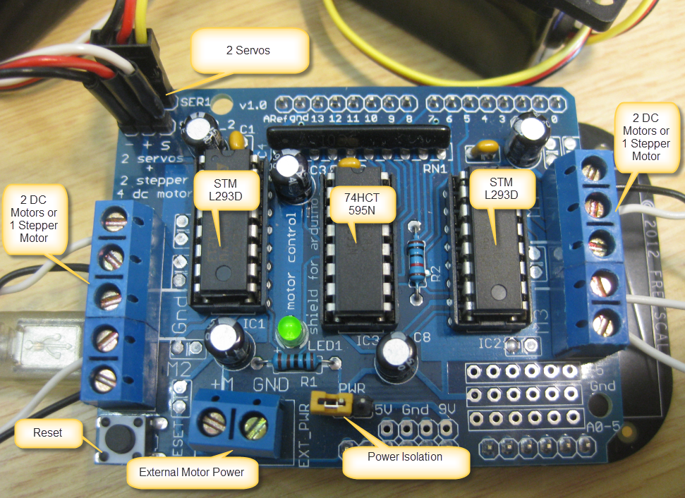
Arduino Motor Stepper Servo Shield with FRDM-KL25Z
The series starts with a tutorial how to drive two servo motors. And if this is not what you are expecting to do with this shield, then you can vote and tell me what you want to see instead on this motor shield :-).
OEM or Original?
The original Arduino Motor/Stepper/Servo Shield is available from Adaftruit Industries and costs less than $20. I’m using a OEM version, see this link. The functionality is the same, except that the OEM version only runs with motors up to 16 VDC, while the original shield is for motors up to 25 VDC.
Motor Stepper Servo Shield Details
The board has two STMicroelectronics L293D Motor H-Bridge IC’s which can drive up to 4 DC motors (or up to 2 stepper motors) with 0.6 A per bridge (1.2 A peak). The 74HCT595N (my board has the SN74HC595 from Texas Instrument) is a shift register used for the H-Bridges to reduce the number of pins needed (more about this in a next post). A terminal block with jumper is providing power to the DC/stepper motor. The 5 VDC for the servos is taken from the FRDM board.
❗ The FRDM-KL25Z can only give a few hundred mA on the 5V Arduino header. That works for small servos, but I recommend to cut the 5V supply to the servos and use a dedicated 5V (or 6V) for the servos.
Outline
In this tutorial, I’m creating a project with CodeWarrior for MCU10.4 for the FRDM-KL25Z board, and then add support for two servo motors.
Processor Expert Components
This tutorial uses added Processor Expert components which are not part of CodeWarrior distribution. The following other components are used:
- Wait: allows waiting for a given time
- Servo: high level driver for hobby servp motors
Make sure you have the latest and greatest components loaded from GitHub. Instructions how to download and install the additional components can be found here.
Creating CodeWarrior Project
To create a new project in CodeWarrior:
- File > New > Bareboard Project, give a project name
- Specify the device to be used: MKL25Z128
- OpenSDA as connection
- I/O support can be set to ‘No I/O’
- Processor Expert as Rapid Application Development option
This creates the starting point for my project:

New Servo Project Created
Servo Motor
Servo motors are used in RC (Radio Control) or (hobby) robotics.

Typical Servo Motor (Hitec HS-303)
The motor has 3 connectors:
- GND (Black)
- Power (Red), typically 5V, but can be 6V or even higher
- PWM (White or Yellow), signal for position information
The PWM signal typically has frequency of 50 Hz (20 ms), with a duty (high duration) between 1 ms and 2 ms.
The screenshot below shows such a 50 Hz Signal with 1.5 ms duty cycle (servo middle position):
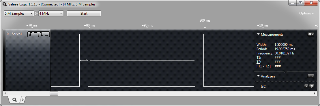
Servo Signal
💡 Many servos go below 1 ms and beyond 2 ms. E.g. many Hitec servos have a range of 0.9…2.1 ms. Check the data sheet of your servos for details. If you do not have a data sheet, then you might just experiment with different values.
With a PWM duty of 1 ms to 2 ms within a 20 ms period, this means that only 10% of the whole PWM duty are used. This means if you have a PWM resolution of only 8bits, then only 10% of 256 steps could be used. As such, an 8bit PWM signal does not give me a fine tuned servo positioning.
The duration of the duty cycle (1..2 ms) is translated into a motor position. Typically the servo has a built-in closed-loop control with a microcontroller and a potentiometer.
💡 I have found that it is not important to have an *exact* 50 Hz PWM frequency. You need to experiment with your servo if it works as well with a lower or higher frequency, or with non-fixed frequency (e.g. if you do a software PWM). Many servos build an average of the duty cycle, so you might need to send several pulses until the servo reacts to a changed value.
Servo Processor Expert Component
I’m using here my own ‘Servo’ component which offers following capabilities:
- PWM configuration (duty and period)
- Min/Max and initialization values
- Methods to change the duty cycle
- Optional command line shell support: you can type in commands and control the servo. This is useful for testing or calibration.
- Optional ‘timed’ moving, so you can move the servo faster or slower to the new position in an interrupt driven way
💡 Of course it is possible to use servos without any special components.
From the Components view, I add the Servo component. To add it to my project, I can double-click on it or use the ‘+’ icon in that view:

Servo Component in Components Library View
💡 In case the Processor Expert views are not shown, use the menu Processor Expert > Show Views
This will add a new ‘Servo’ component to the project:
Servo Component added
But it shows errors as first the PWM and pin settings need to be configured.
PWM Configuration
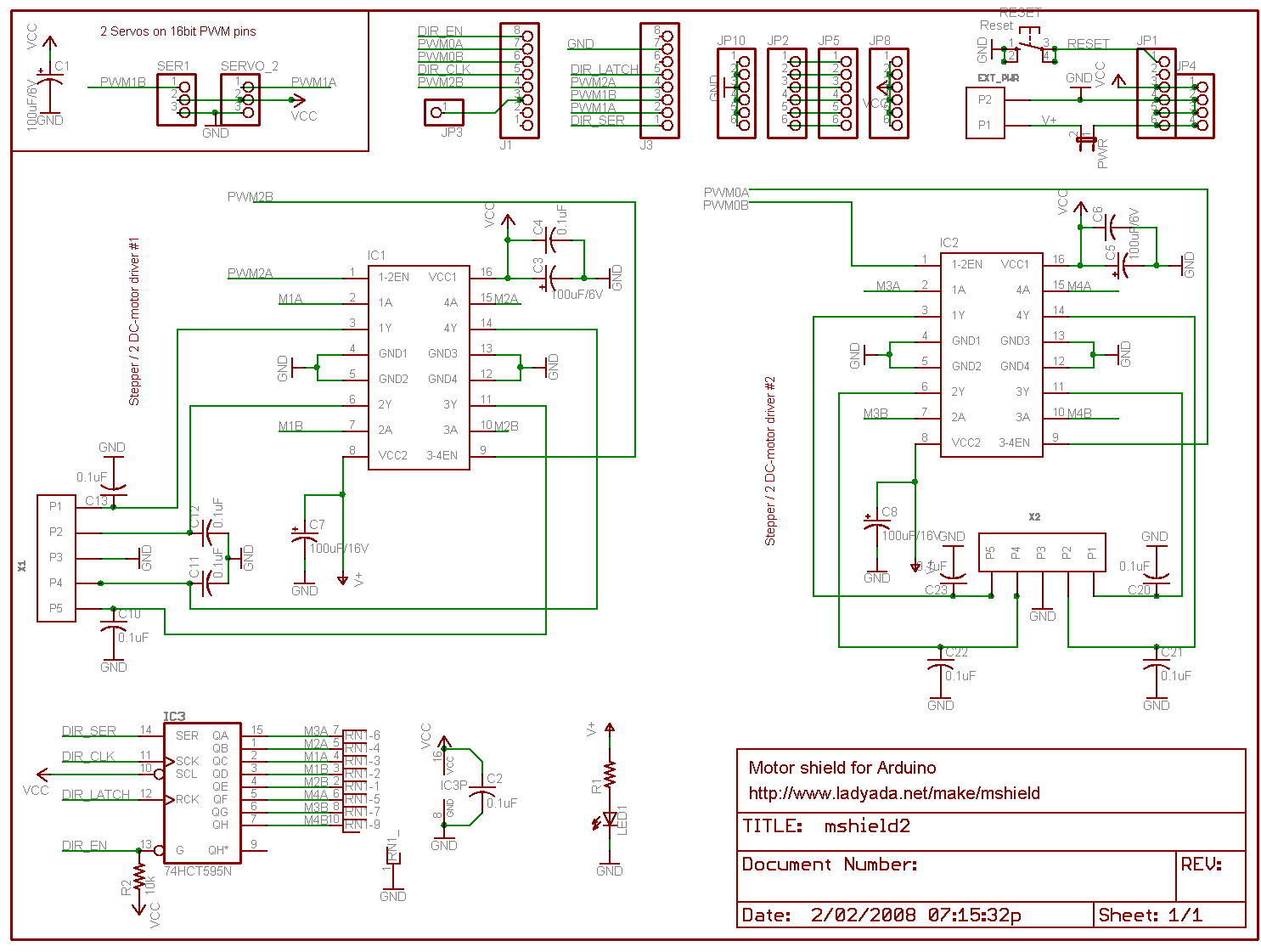
On the Arduino Motor/Stepper/Servo shield the two Servo motor headers are connected to PWM1B and PWM1A (see schematic):

Servo Header on Board (Source: DK Electronics Shield Schematic)
Following the signals, this ends up at following pins on the KL25Z:
- Servo 1 => PWM1B => Arduino Header D10 => FRDM-KL25Z D10 => KL25Z pin 73 => PTD0/SPI0_PCS0/TPM0_CH0
- Servo 2 => PWM1A => Arduino Header D9 => FRDM-KL25Z D9 => KL25Z pin 78 => ADC0_SE6b/PTD5/SPI1_SCK/UART2_TX/TPM0_CH5
From the pin names on the Kinets (TPM0_CH0 and TPM0_CH5) I can see that this would be the same Timer (TPM0), but with different channel numbers (CH0 and CH5).
For my first servo Processor Expert has created for me a ‘TimerUnit_LDD’ which I will be able to share (later more on this). The TimerUnit_LDD implements the ‘Logical Device Driver’ for my PWM:

TimerUnit_LDD
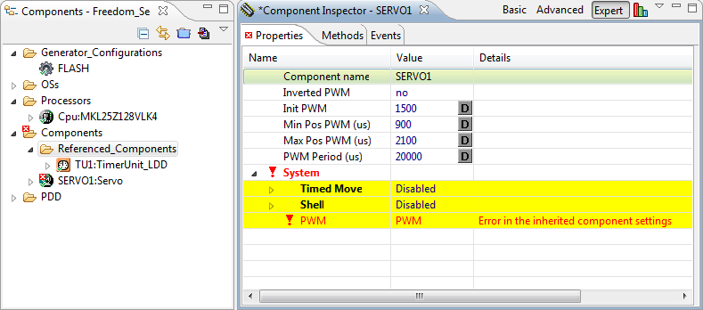
So I select the PWM component inside the Servo component and configure it for TPM0_C0V and the pin PTD0/SPI0_PCS0/TPM0_CH0 with low initial polarity. The period of 20 ms (50 Hz) and starting pulse with of 1.5 ms (mid-point) should already be pre-configured:

Servo1 PWM Configuration
💡 I recommend to give it a pin signal name (I used ‘Servo1’)
❗ That I need to set the ‘initial polarity’ to low is a bug of Processor Expert in my view: the device supports an initial ‘high’ polarity, but somehow this is not implemented? What it means is that the polarity of the PWM signal is now inverted: a ‘high’ duty cycle will mean that the signal is low. We need to ‘revert’ the logic later in the Servo component.
Because of the inverted PWM logic, I need to set the ‘Inverted PWM’ attribute in the Servo component:

Inverted PWM
The other settings of the Servo component we can keep ‘as is’ for now. The ‘Min Pos PWM’ and ‘Max Pos PWM’ define the range of the PWM duty cycle which we will use later for the servo position.
Adding Second Servo
As with the first servo, I add the second servo from the Components Library view. As I already have a TimerUnit_LDD present in my system, Processor Expert asks me if I want to re-use the existing one or to create a new component:

Shared Component Dialog
As explained above: I can use the same timer (just a different pin/channel), so I have my existing component selected and press OK.
As above, I configure the timer channel and pin with initial polarity:

Servo2 PWM Configuration
And I should not forget to enable the inverted logic:

Inverted PWM for Servo2
Test Application
Time to try things out. For this I create a simple demo application which changes the position of both servos. First I add the Wait component to the project from the Components Library:

Added Wait Component
As I have all my Processor Expert components configured, I can generate the code:

Generating Processor Expert Code
Next I add a new header Application.h file to my project. For this I select the ‘Sources’ folder of my project and use the New > Header File context menu to add my new header file:

New Application.h
In that header file Application.h I add a prototype for my application ‘run’ routine:

Added APP_Run Prototype
From the main() in ProcessorExpert.c, I call that function (not to forget to include the header file):
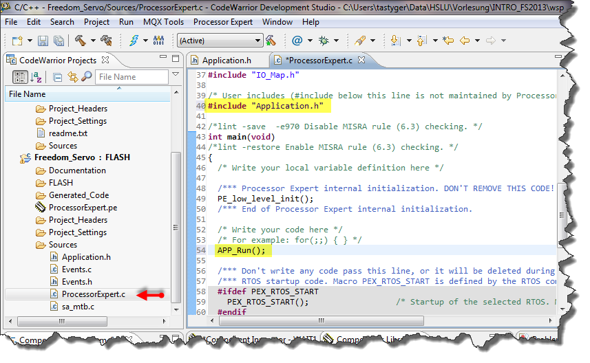
Calling APP_Run from main
The same way I add a new source file Application.c:

New Application.c
To test my servos, I’m using the SetPos() method which accepts a 8bit (0 to 255) value which is the position. To slow things a bit, I’m waiting a few milliseconds between the different positions:
#include "Application.h" #include "WAIT1.h" #include "SERVO1.h" #include "SERVO2.h" void APP_Run(void) { uint16_t pos; for(;;) { for(pos=0;pos<=255;pos++) { SERVO1_SetPos(pos); SERVO2_SetPos(pos); WAIT1_Waitms(50); } } }Save all files, and we should be ready to try it out on the board.
Build, Download and Run
That’s it :-). Time to build the project (menu Project > Build Project) and to download it with the debugger (menu Run > Debug) and to start the application. If everything is going right, then the two servos will slowly turn in one direction until the end position, and then return back to the starting position.
Summary
Using hobby servo motors with the FRDM-KL25Z, CodeWarrior, Processor Expert and the additional components plus the Arduino/Stepper/Servo Shield is very easy in my view. I hope this post is useful to start your own experiments with hobby servo motors to bring any robotic project to the next level :-).
I have here on GitHub a project which features what is explained in this post, but with a lot more components, bells and whistles :-).
What’s next?
Actually, I have several things in mind. But I let the readers of this post vote :-):
Or simply post a comment about what you have in mind.
The next tutorial is about timed servo moves.
List of Tutorials
- Tutorial: Arduino Motor/Stepper/Servo Shield – Part 1: Servos
- Tutorial: Arduino Motor/Stepper/Servo Shield – Part 2: Timed Servo Moves
- Tutorial: Arduino Motor/Stepper/Servo Shield – Part 3: 74HCT595 Shift Register
Happy Servoing 🙂

Pingback: Tutorial: Arduino Motor/Stepper/Servo Shield – Part 2: Timed Servo Moves | MCU on Eclipse
Pingback: Tutorial: Arduino Motor/Stepper/Servo Shield – Part 3: 74HCT595 Shift Register | MCU on Eclipse
I got this shield but to drive a stepper motor from a cdrom instead. I have no idea how to power it.
LikeLike
To power the shield: the logic is powered from the FRDM board. For the motor power supply there is a separate power connector.
LikeLike
Ok, I figured out how to power and drive the shift register, but do you need PWM for the stepper motors? or is it just for servos?
LikeLike
I figured it out, I followed your second part of the tutorial on the shift register, and checked out the L293D IC connections, sent the bytes for a simple rotation and it works. I am using an old desktop power supply 5v output to power the motor externally. Its pretty sleek. I was able to use both MSB first and LSB first. Now I am not sure how to make just a single turn, or turn just a few degrees. I checked your tutorial on usig the reset button as an input, that worked too :). Thanks for these tutorials man.
LikeLike
Allways at your service!
LikeLike
I got a similar motor shield but to drive a DC motor.
I have a problem because when I send something to the shield to move a servo, it answers me but if I sent something to move a DC motor, it doesn’t answers.
LikeLike
What do you mean with ‘answers me’? You mean it moves? Keep in mind that the signal for a DC motor and for a servo motor are completely different.
LikeLike
You say you’re using your own Servo Processor Expert Component. Where can it be found? Thanks.
LikeLike
Hi AK,
its in the component set released on SourceForge, see https://mcuoneclipse.com/2014/10/21/mcuoneclipse-releases-on-sourceforge/
LikeLike
hi i have this shield and i was wondering would there be a way to hack the shields code for then you could another shield using the analogue pins, as i need 8 motors and i wont to only use one arduino.
LikeLike
This all depends on what exactly you want to do. Using the analog pins only will work if you can mux the pins for PWM signals.
LikeLike
would you know how to mux the pins for the PWM signals
because i looked at the code for the shield (it’s a adafruit motor shield v1) and i only half understand it
LikeLike
the simplest and easiest way is if you use Processor Expert: it will do the Muxing for you.
LikeLike
hey Erich, i’m trying to run this project using the Arduino motor shield V2.2. the Enable A/B LEDs are on and I checked the other available pins to make sure I didn’t have the PWM linked to the wrong pins but the servos aren’t going through their routine. I’ve tried connecting an external 6V power supply but I’m still not getting anything. What could the problem be?
LikeLike
Hi Ryan,
can you check both the motor signals and the PWM with a logic analyzer?
Erich
LikeLike
Hey Erich, thank you for your timely response!
I don’t have a logic analyzer readily available, sorry about that. my main goal is to merge concepts from your “accelerating the kl25z freedom board” with my motor shield to create a self stabilizing system using the MMA8451. I am pretty green when it comes to CW and processor expert but I’ve been able to learn through your tutorials. as for the servos I wish I had a logic analyzer so I could tell you if i’m getting a signal to the servos, but alas I don’t have one in my immediate possession.
LikeLike
Hi Erich
I am a beginner and try to build a robot with this motor shield. My 4 motors run without any problems, but the servo i would like to use for the Ultrasonic sensor acts very strange. Connected directly to the arduino it works OK, connected to the motorshield it acts like a continuos servo, it allways turns to the right side and does not go back. I have to stop it, because it would damage the servo. I tried a second motor shield and have the same problem.
It would be very nice if you could give me a tipp what I could do.
Thank you
Franz
LikeLike
I am sorry, after days of trying I found out that I uses the pin of the Ultrasonic trigger. My excuse, I am a dynosaur of over 70.
Greetings and please delete my question
Fran
LikeLike
Hi Franz,
ah, I see you found it 🙂 And no worries: using the wrong pin happens to me from time to time too. Again: having something to inspect the signal is always the best way to find out what is going on.
Erich
LikeLike
Hi Franz,
hard to tell from remote, but I suggest that you hook up a logic analyzer/oszilloscope to that pin to see how the signal looks like.
I hope this helps,
Erich
LikeLike
Thank you Erich,
Regards
Franz
LikeLike
Erich, good morning. Excellent your tutorial. Please, help me if you can. I need to drive two steppers(NEMA17) with Arduino, ShieldL293D and Joystick to control the directions and speed of the steppers. Do you have code that do this? Thanks a lot.
LikeLike
Hi Marco,
no, I have not published the code for that. Check the data sheet of the L293D how you can drive the stepper motor. If in doubt, check the many articles on the web how you can use full H-bridges to drive a stepper motor. Using the Joystick is just on top of this. I hope this helps.
LikeLike
Hi Erich, how are you doing?
I have a question…my motor shield is L293D dual, which can controlk up to 4 DC motors. But I am having problems to make it work using serial communication port. How could I use the L293D only by changing the input levels using HIGH and LOW, instead of serial signal? Thank you and keep it up this good jog! Regards.
LikeLike
Hi Erich! I want ask you if you know where find the instructions to use a frdm kl25z and the Adaftruit’s motor shield of this post with DC motors. Thanks!
LikeLike
Hi Carlos,
have a look here: https://mcuoneclipse.com/2012/12/14/frdm-kl25z-with-the-arduino-motor-shield/
I hope this helps,
Erich
LikeLike