In Part 1 of this series I have covered the SD card on the Arduino Ethernet shield. In Part 2 I’m hooking up the board to the network and will be able to ping it 🙂

Arduino Ethernet Shield with FRDM-KL25Z
List of Tutorials
- FRDM with Arduino Ethernet Shield R3, Part 1: SD Card
- FRDM with Arduino Ethernet Shield R3, Part 2: Ping
- FRDM with Arduino Ethernet Shield R3, Part 3: Embedded Web Server
- FRDM with Arduino Ethernet Shield R3, Part 4: MinIni
Hardware
The W5100 has a TCP/IP stack built into the hardware, which makes it easy to use with any small microcontroller, including the Freescale KL25Z on the FRDM-KL25Z board. The Arduino Ethernet Shield R3 I’m using requires a hardware change to map the SPI signals to the Arduino header: See Part 1 of this series.
SPI Communication
The W5100 uses the ‘Mode 0’ SPI protocol:
- Clock Idle polarity low
- Data shifted on rising edge
After activivating the CS (Chip Select, LOW active) line, a command byte (0xF0 for write, 0x0F for read) is sent, followed by the address (16bit, most significant byte first), and then the data byte. Within a byte, the MSB (Most Significant Bit) is sent first.
Write
The screenshot below shows the write command 0xF0 which writes the value 0xC0 to address 0x0001:
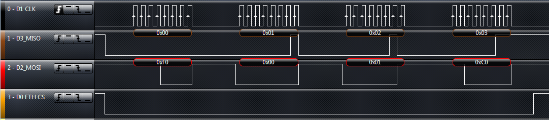
W5100 SPI Write Byte
So a transaction is always 32 bits: 1 command byte, 2 address bytes, one data byte. As you can see, the W5100 responds on the MISO line with increasing values to the write command.
Read
Reading from the device is very similar. For this the command 0x0F is used. Below is the read operation which reads back the value from address 0x0001:

W5100 SPI Read Byte
Chip Select
The chip select for the W5100 is low active, and to abstract from the hardware, I’m using defines:
#define W5100_CS_ENABLE()   ETH_CS_ClrVal()
#define W5100_CS_DISABLE()  ETH_CS_SetVal()
Semaphore
As the SPI bus is shared between the SD card and W5100, I’m using a semaphore to grant mutual access to the bus:
static xSemaphoreHandle SPImutex = NULL; /* Semaphore to protect SPI access */

void W5100_RequestSPIBus(void) {
  (void)xSemaphoreTakeRecursive(SPImutex, portMAX_DELAY);
}

void W5100_ReleaseSPIBus(void) {
  (void)xSemaphoreGiveRecursive(SPImutex);
}

void W5100_GetBus(void) {
  W5100_RequestSPIBus();
  W5100_CS_ENABLE();
}

void W5100_ReleaseBus(void) {
  W5100_CS_DISABLE();
  W5100_ReleaseSPIBus();
}
SPI Read and Write
Using the Processor Expert SPI component, dealing with the SPI protocol gets really simple. I need to catch the hook for the finished SPI transaction and wait until the transaction is finished:
static volatile bool W5100_DataReceivedFlag = FALSE;

void W5100_OnBlockReceived(LDD_TUserData *UserDataPtr) {
  (void)UserDataPtr;
  W5100_DataReceivedFlag = TRUE;
}

static void SPIWriteByte(unsigned char write) {
  unsigned char dummy;

  W5100_DataReceivedFlag = FALSE;
  (void)SM1_ReceiveBlock(SM1_DeviceData, &dummy, sizeof(dummy));
  (void)SM1_SendBlock(SM1_DeviceData, &write, sizeof(write));
  while(!W5100_DataReceivedFlag){}
}

static uint8_t SPIReadByte(void) {
  uint8_t val, write = 0xff; /* dummy */

  W5100_DataReceivedFlag = FALSE;
  (void)SM1_ReceiveBlock(SM1_DeviceData, &val, 1);
  (void)SM1_SendBlock(SM1_DeviceData, &write, 1);
  while(!W5100_DataReceivedFlag){}
  return val;
}
❗ This code polls for the DataReceivedFlag. To make the code more robust, a timeout should be used. I keep things simple here.
Read/Write Registers
To read and write the W5100 registers, this can be done like this:
uint8_t W5100_MemWriteByte(uint16_t addr, uint8_t val) {
  W5100_GetBus();
  SPIWriteByte(W5100_CMD_WRITE);
  SPIWriteByte(addr>>8); /* high address */
  SPIWriteByte(addr&0xff); /* low address */
  SPIWriteByte(val); /* data */
  W5100_ReleaseBus();
  return ERR_OK;
}

uint8_t W5100_MemReadByte(uint16_t addr, uint8_t *val) {
  W5100_GetBus();
  SPIWriteByte(W5100_CMD_READ);
  SPIWriteByte(addr>>8); /* high address */
  SPIWriteByte(addr&0xff); /* low address */
  *val = SPIReadByte(); /* data */
  W5100_ReleaseBus();
  return ERR_OK;
}
Read/Write Multiple Bytes
To read or write more than one byte, the single byte read/write routines are used:
uint8_t W5100_MemReadBlock(uint16_t addr, void *data, size_t dataSize) {
  while(dataSize>0) {
    if (W5100_MemReadByte(addr, (uint8_t*)data)!=ERR_OK) {
      return ERR_FAILED;
    }
    data++; addr++; dataSize--;
  }
  return ERR_OK;
}

uint8_t W5100_MemWriteBlock(uint16_t addr, void *data, size_t dataSize) {
  while(dataSize>0) {
    if (W5100_MemWriteByte(addr, *((uint8_t*)data))!=ERR_OK) {
      return ERR_FAILED;
    }
    data++; addr++; dataSize--;
  }
  return ERR_OK;
}
An example to read/write multiple bytes is for the network configuration:
typedef struct w5100_config {
  uint8_t gateway[4]; /* gateway address, e.g. 192.168.0.1 */
  uint8_t netmask[4]; /* network mask, e.g. 255.255.255.0 */
  uint8_t hwaddr[6]; /* hardware MAC address, e.g. 90:a2:da:0D:42:dd */
  uint8_t ipaddr[4]; /* own IP address, e.g. 192.168.0.90 */
} w5100_config_t;

uint8_t W5100_WriteConfig(w5100_config_t *config) {
  return W5100_MemWriteBlock(W5100_GAR0, (void*)config, sizeof(w5100_config_t));
}

uint8_t W5100_ReadConfig(w5100_config_t *config) {
  return W5100_MemReadBlock(W5100_GAR0, (void*)config, sizeof(w5100_config_t));
}
I will cover this more later.
Application Initialization
With this, we are ready to configure the W5100 :-).
Mode Register
The W5100 has the MR (Mode Register) register with the following bits:
#define W5100_MR  0x00 /* MR (Mode Register */
#define W5100_MR_BIT_IND(1<<0) /* indirect bus interface mode */
#define W5100_MR_BIT_AI(1<<1) /* address auto-increment in indirect bus interface, 1 to enable */
#define W5100_MR_BIT_PPPoE (1<<3) /* PPPoE mode, 1 to enable */
#define W5100_MR_BIT_PB (1<<4) /* ping block bit, 1 to block pings */
#define W5100_MR_BIT_RST  (1<<7) /* reset bit, 1 to reset internal registers */
Of interest is the RST (Reset) bit. Setting it to one will reset the device:
CLS1_SendStr((unsigned char*)"Reset W5100.\r\n", CLS1_GetStdio()->stdOut);
/* reset device */
if (W5100_MemWriteByte(W5100_MR, W5100_MR_BIT_RST)!=ERR_OK) {
  CLS1_SendStr((unsigned char*)"Failed to reset device!\r\n", CLS1_GetStdio()->stdErr);
}
Network Address
Next, I need to configure the network address information. For this I need to configure the gateway, the network mask, IP address and the MAC (Hardware Address). The MAC address I can find on the sticker of my Ethernet Shield:

Ethernet Shield MAC Address
With this, I set up my network configuration like this:
static const w5100_config_t W5100_config = {
  {192, 168, 1, 1}, /* gateway */
  {255, 255, 255, 0}, /* netmask */
  {0x90, 0xa2, 0xda,0x0D, 0x42, 0xdd}, /* hw/mac address */
  {192, 168, 0, 80} /* ip address */
};
And configure it:
CLS1_SendStr((unsigned char*)"Configure network.\r\n", CLS1_GetStdio()->stdOut);
/* configure network: IP address, gateway, netmask, MAC */
if (W5100_WriteConfig((w5100_config_t*)&W5100_config)!=ERR_OK) {
  CLS1_SendStr((unsigned char*)"Failed to set Net Configuration!\r\n", CLS1_GetStdio()->stdErr);
}
RX/TX Memory Buffer
The W5100 can deal with up to 4 network sockets, with a total of 2×8 KByte for RX (RMSR register) and TX (TMSR register) buffers. Default is to use 2 KByte for each socket:
CLS1_SendStr((unsigned char*)"Configure RX/TX memory.\r\n", CLS1_GetStdio()->stdOut);
/* we have 8 KByte we can use for the RX and TX sockets: */
if (W5100_MemWriteByte(W5100_RMSR,
     W5100_xMSR_SOCKET_1_MEM_SIZE_2KB
    |W5100_xMSR_SOCKET_2_MEM_SIZE_2KB
    |W5100_xMSR_SOCKET_3_MEM_SIZE_2KB
    |W5100_xMSR_SOCKET_4_MEM_SIZE_2KB
  )!=ERR_OK)
{
  CLS1_SendStr((unsigned char*)"Failed to set RX socket memory size!\r\n", CLS1_GetStdio()->stdErr);
}
if (W5100_MemWriteByte(W5100_TMSR,
     W5100_xMSR_SOCKET_1_MEM_SIZE_2KB
    |W5100_xMSR_SOCKET_2_MEM_SIZE_2KB
    |W5100_xMSR_SOCKET_3_MEM_SIZE_2KB
    |W5100_xMSR_SOCKET_4_MEM_SIZE_2KB
   )!=ERR_OK)
{
  CLS1_SendStr((unsigned char*)"Failed to set TX socket memory size!\r\n", CLS1_GetStdio()->stdErr);
}
💡 There are other things to configure like number of retry, but I keep them on the default values for now.
Status Output
I have added a command line shell interface to the W5100 driver, so I can inspect my network configuration:

Status Network Configuration
Ping
Finally, time to see if the W5100 responds on ping commands. For this I ‘ping’ the IP address I have assigned:

Ping my Board
Congratulations!
💡 If pinging does not work: check the network address and network setup. If the W5100_MR_BIT_PB bit is set in the W5100_MR register, then the W5100 does *not* respond to pings!
Summary
I have now the FRDM-KL25Z hooked up to the network with the Arduino Ethernet shield. It does not much for now, it only responds to pings, but this is a good starter ;-). The software project is available on GitHub.
💡 I recommend to have a look this very good blog post by rwb.
Happy Pinging 🙂

Hi 🙂
I’ve bought an ethernet module, which has the enc28j60.. Do you know if there is many differences between work with this or with the W5100? W5100 is easier?
LikeLike
Hi 🙂
I have not used the enc28j60. The W5100 is very easy to be used in my view, and featured as well in many open source (and Arduino) projects. And is out there for a long time already, very stable and issues are known. But it all depends what you need: the W5100 supports up to 4 sockets with a total of 8 KByte of RAM. But this should be enough for many typical small projects anyway.
LikeLike
The enc28j60 is different. The Wiznet modules do a lot of the work for you and have more built-in capabilities.
LikeLike
Pingback: FRDM with Arduino Ethernet Shield R3, Part 3: Embedded Web Server | MCU on Eclipse
Pingback: FRDM with Arduino Ethernet Shield R3, Part 1: SD Card | MCU on Eclipse
Pingback: FRDM with Arduino Ethernet Shield R3, Part 4: MinIni | MCU on Eclipse
Hello. Very good project. I have a web server running and with time syncronization, but working in a simple network. With a complex o bigger network, the time sync don’t work, because i need to set the DNS (i must to use fixed IP). How i can to do to set the DNS 8.8.8.8?
LikeLike
you have to bypass DHCP and provide your own static configuration.
LikeLike
I would like to implement just the same approach for iMX RT685 board and W5500 chip. Unfortunately your GitHub link looks broken. Please let me know if your source code is still available. Thank you in advance!
LikeLiked by 1 person
Hi Slava,
thanks for reporting the broken link. Things on GitHub have moved around, but things are still there. I have fixed the link now. Can you check it again?
Thanks,
Erich
LikeLike
Thank you very much for the fix! This is really interesting project.
LikeLike