
I’m making progress on my larger split-flap project (see Update on the Split-Flap Project for 2025). So far I have 32 operational for the larger 64 flap installation. In parallel, I worked on a smaller 4 flaps unit used as a clock.

Outline
For building such split flap units, I have merged electronics with different tools:
- Laser cut flap spools and motor holder
- 3D printed flap stopper
- CNC cut wood for the enclosure
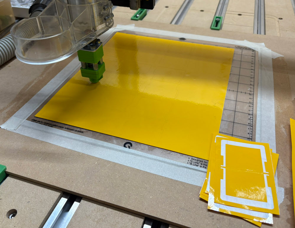
- CNC cut PVC split flaps
- CNC vinyl cutting for the flap text

If you are interested in the overall process, I recommend having a look at my other article. You can find it here: DIY Split-Flap Display.
Beech Wood Enclosure
In the past I have used a laser-cut MDF (Medium Density Fibreboard) front panel for my split-flaps. That was easy and cheap, but for my taste not aesthetic enough. I really love the look and feel of real wood. I decided to use beech hard wood for the new enclosure.
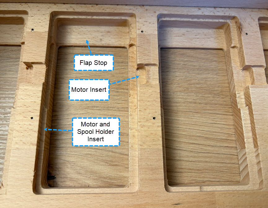
The enclosure is CNC cut out of 18 mm beech wood. Below how the openings for the flaps are cut out for the front panel:

Laser-Cut Spool Holder
The split flap spools and holder for the motors and sensor are laser-cut out of 3 mm HDF (High Density Fibreboard):
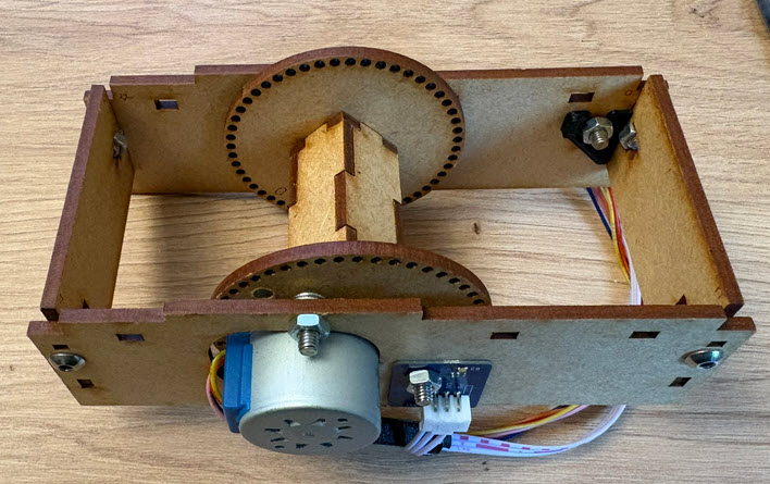
The design is a modified version of the design by Scott Bezek.
Flap Letters
The previous spools with 40 flaps has been extended to 52 flaps.
With this I have more letters (.-äöüéèà) plus four colors (red, blue, black, yellow) available.

Spool Holder
The spool holders then are inserted into the back side of the front panel. The hardwood needs to be precisely cut, with 1 mm of wood remaining for the flap stopper. The cut-outs holding the spool and motor holder are ‘press-fit’.
Enclosure
The enclosure has enough space for four split flap units:

Below an image of the front side with the empty enclosure:

Electronics
To control the four split flaps, I’m using the K22FN512 micro-controller from NXP, using the tinyK22 breakout board.
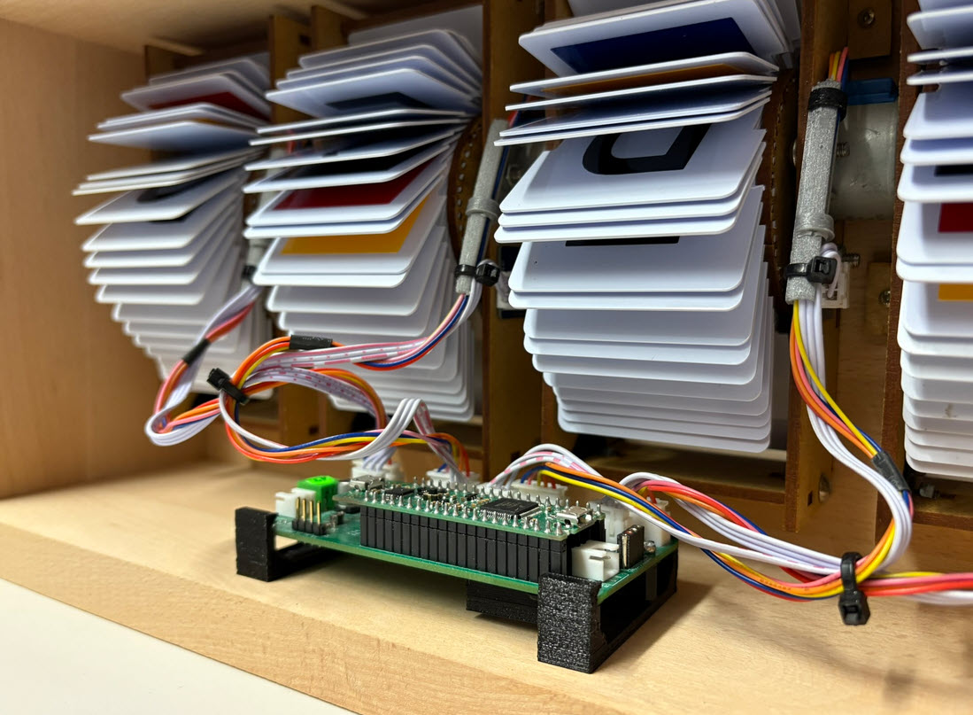
The board is capable of driving up to four stepper motors with sensors. It includes an DS3232 external RTC with backup battery plus external UART and RS-485 interface.
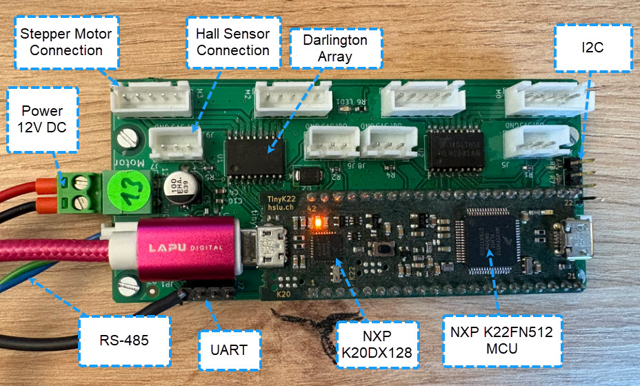
The RS-485 connection is used to connect multiple units.

Summary
In the video below, the unit does a power-on-reset, finds the zero position using the magnets and hall sensor, and then shows the current time:
The beech wood enclosure adds value to this split flap unit. With the four flaps its primary purpose is to show the time. Also, it displays random 4-letter words, the date or time. I’m very happy with the result. I’ll continue working on the larger installation with up to 64 split-flaps.
Happy flapping 🙂
Links
- Update on the Split-Flap Project for 2025 shows the larger build (work in progress)
- DIY Split-Flap Display with details how to build one
- Scott Bezek: https://github.com/scottbez1/splitflap

Pingback: Building a DIY split-flap clock « Adafruit Industries – Makers, hackers, artists, designers and engineers!