
For a research project and demonstrator at HSLU university I have to measure voltage a DC voltage and current. For this I’m planning to use the Texas Instrument Texas Instruments INA260, so I had to quickly develop a software driver for it.
Outline
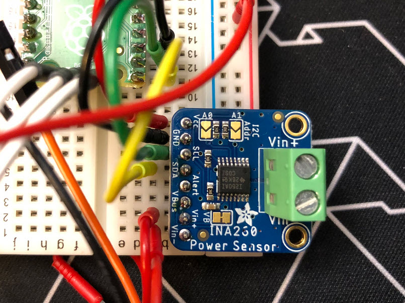
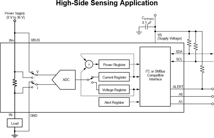
The TI INA260 is a really cool and flexible power sensor sensor. It can be used for up to +36 V DC and up to 15 A current, both on the high and low side. The I2C interface makes it easy to use, and has the shunt resistor integrated.
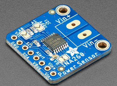
To support the research project, a new driver for the INA260 has been added to the McuLib. To develop the driver, I have used the Adafruit INA260 breakout board ($9.95).
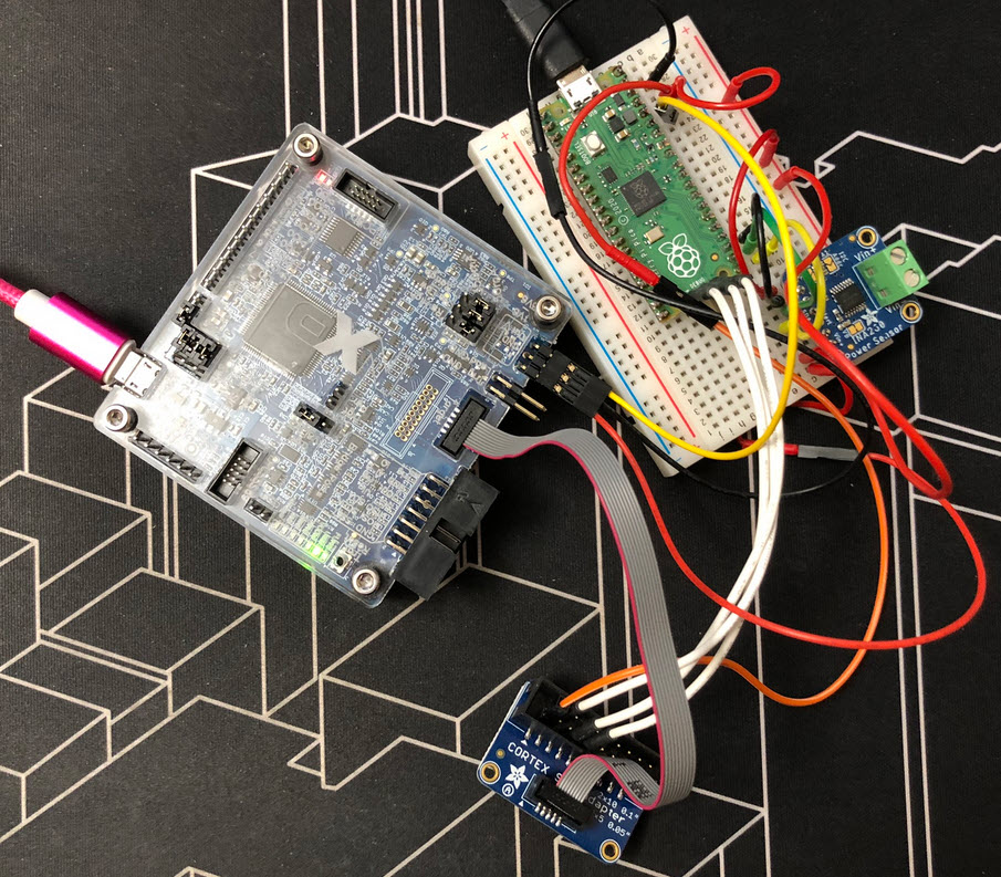
To verify the driver and accuracy, a test bench with an RP2040 and MCU-Link Pro is used, below the software running on the RP2040 is measuring its own current consumption, and checked by the power measurement of the MCU-Link Pro:
McuINA260 Driver
The driver comes with three files:
- config/McuINA260config.h: configuration items, e.g. I2C address.
- src/McuINA260.h: interface file.
- src/McuINA260.c: implementation file.
In the header file all device registers are listed:
/* TI INA260 device registers: */
typedef enum INA260_REG_e {
  McuINA260_ADDR_CONFIGURATION_REGISTER           = 0x00,
  McuINA260_ADDR_CURRENT_REGISTER                 = 0x01,
  McuINA260_ADDR_BUS_VOLTAGE_REGISTER             = 0x02,
  McuINA260_ADDR_POWER_REGISTER                   = 0x03,
  McuINA260_ADDR_MASK_ENABLE_REGISTER             = 0x06,
  McuINA260_ADDR_ALERT_LIMIT_REGISTER             = 0x07,
  McuINA260_ADDR_MANUFACTURER_ID_REGISTER         = 0xFE,
  McuINA260_ADDR_DIE_ID_REGISTER                  = 0xFF,
} INA260_REG_e;
It is possible to read/write the device registers:
/*!
 * \brief Read a device register
 * \param reg Device register
 * \param value Pointer where to store the register value
 * \return Error code, ERR_OK if everything is ok.
 */
uint8_t McuINA260_ReadRegister(INA260_REG_e reg, uint16_t *value);

/*!
 * \brief Write a device register
 * \param reg Device register
 * \param value Register value to write
 * \return Error code, ERR_OK if everything is ok.
 */
uint8_t McuINA260_WriteRegister(INA260_REG_e reg, uint16_t value);
To read voltage, current and power, separate functions to get the values are provided:
/*!
 * \brief Read the bus voltage measurement value from the device.
 * \return Power value in mV (micro-Volt).
 */
uint32_t McuINA260_ReadVoltage(void);

/*!
 * \brief Read the power measurement value from the device.
 * \return Power value in mW (milli-Watt).
 */
uint32_t McuINA260_ReadPower(void);

/*!
 * \brief Read the current measurement value from the device.
 * \return Current value in uA (micro-Amps).
 */
int32_t McuINA260_ReadCurrent(void);
Command Line Interface
The driver includes a command-line interface (e.g. with the McuShell) and offers different commands:
INA260                    ; Group of INA260 commands
  help|status             ; Print help or status information
  reset                   ; Reset the device with the reset bit
  config <val>            ; Write a value to the configuration register
The command line interface can report the status:
McuINA260    : INA260 sensor status
  I2C addr   : 0x40
  Config     : 00h: 0x6127
  Current    : 01h: 0x000E, 17.500 mA
  Bus voltage: 02h: 0x0F85, 4966.250 mV
  Power      : 03h: 0x0009, 90 mW
  Alert limit: 07h: 0x0000
  Manufac. ID: FEh: 0x5449
  Die ID     : FFh: 0x2270
With this, I have a driver and infrastructure which I can use for my measurements.
Summary
It only took me a few hours to develop the INA260 driver, thanks to the Adafruit INA260 breakout board. The driver implements all the necessary functions and configuration needed. Currently the alert function of the INA260 is not used, but can be easily added later easily. The driver currently supports a single INA260 on a bus So if you need a simple driver for the INA260, it is available on GitHub.
Happy measuring 🙂
💡 Another sensor I would like to look at is the TI INA219. So this might be something for the next days.
Links
- TI INA260 data sheet: https://www.ti.com/product/INA260
- Adafruit INA260 breakout board: https://www.adafruit.com/product/4226
- McuLib on GitHub: https://github.com/ErichStyger/McuOnEclipseLibrary

Nice! I have been using INA219 in one of recent projects. Very neat ICs and easy to implement. Somehow I haven’t heard about INA260 before. That’s an interesting feature to integrate the shunt resistor,
Why are you considering change INA260 to INA219?
All the best in New Year!
LikeLike
Hi Adam,
The INA260 is super easy to use as it has the shunt resistor integrated, plus it it is very accurate over a wide range of voltage and current. The reason why I might looking at the INA219 too is because I just have it at hand, and it has a resolution of 0.8 mA vs. 1.25 mA of the INA260. The lower current range of the INA219 still would be good enough for the project in mind.
All the best for the New Year!
LikeLike
INA260 is certainly a fun little thing. I used it for a lot of power measurements for my PhD research.
LikeLike
I really like that it can be configured for different sampling and averaging too.
LikeLike
Pingback: Power Measurement with an INA260 sensor @McuOnEclipse « Adafruit Industries – Makers, hackers, artists, designers and engineers!
I was once admonished by Jim Williams himself during a discussion of a similar circuit. As best as I recall his exact words where “Unless you measure the voltage and current at THE EXACT SAME TIME, the power measurement is meaningless”.This of course gets into the nuance’s of how fast that single ADC is switching between measuring I and V vs how fast I and V are changing (Bandwidth, Phase etc).The LT2940 actual does do the proper four-quadrant multiplication of the simultaneous measures of I and V. See:https://www.analog.com/en/technical-articles/analog-multiplier-monitors-power-and-simplifies-design-of-power-control-loops.html
LikeLike
Jim is 100% right! Thanks for pointing to that LT2940 device: indeed a very sophisticated approach compared to the INA260 which switches between I and V measurements.
LikeLike