
I selected the Bosch BME280 environmental sensor as the heart of my OKdo E1-based weather station. It is convenient to use, and I can prototype with the Mikroe Weather Click board MIKROE-1978. But the sensor is accessed over I2C, and that is my least favourite of the communication interfaces. In this short tutorial, I show you how the MCUXpresso Config tools (Pins, Clocks, Peripherals) are used to set up the I2C driver from the MCUXpresso lpcxpresso55S69 SDK. And very quickly, I am able to communicate with the BME280 sensor.

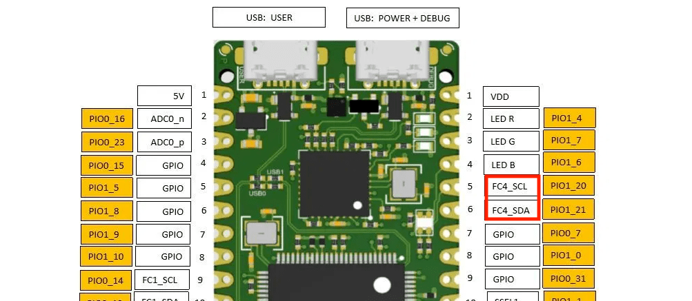
The OKdo E1 board has I2C brought to the expansion header, labelled as FC4_SCL and FC4_SDA in the diagram. For reference, note that these signals are multiplexed onto pads named PIO1_20 and PIO1_21.
I created a new project in MCUXpresso IDE v11.1.0 based on SDK lpcxpresso55s69 v2.7.0 using the New SDK project wizard. It was not necessary to make any changes to the project, and I named in LPC55S69_WeatherStation in the wizard.
CLOCKS CONFIG
We can quickly re-use the tutorial from last week to configure the clocks for the project. Running the Clocks tool…:

… allows us to switch to the Clocks Diagram tab, and then use the Functional Groups Properties icon to edit the functional groups in the project. I added a new functional group, named BOARD_BootClockPLL150M_FRO12, and configured the PLL to be referenced from the clock named fro_12m. Refer back to last week’s tutorial for full details, and don’t forget to select your new Functional Group in the dropdown box at the top of the perspective.
All that remains it to enable the clock to FlexComm4, since this is the FC module that we’ll use for I2C. I used the fro_12m as the clock source for I2C.

PINS CONFIG
Well, that completes the clock configuration. We can use the icons in the top right of the Clocks Config perspective to switch to the Pins view:
Recall that the I2C signals are on pads PIO1_20 and PIO1_21. In my tutorials, I’ll always use the word PAD to mean one of the ports (with a name like PIO1_20 in this case). Depending upon the package (BGA, QFN, LQFP…) that pad will be routed to a pin. On the OKdo E1 board the package is LQFP100, and pad PIO1-21 is routed to pin 4. Pin 4 has many possible multiplexed functions. We use the Pins Config tool to select which of these pad functions is brought out to the pin.
We can configure pads PIO1_20 and PIO1_21 for their I2C functions (I2C_SCL and I2C_SDA, respectively) in the Pins Config tool. Simply search for each pad in the Pins view:
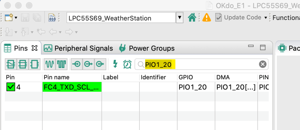
In the diagram above, I already have PIO1_20 routed for I2C function (it is showing green). However, you’ll want to check the checkbox in the first column to mark the pin for routing. A dialog pops up, offering you all the possible pin multiplex functions for the pad. Scroll down through the list and select FlexComm4’s SCL function:

When you put a checkmark (“tick”) in the FC4_TXD_SCL row, the Pins Config tool routes the pad, and you’ll see a new entry (in yellow) in the Routed Pins view at the bottom of the perspective:
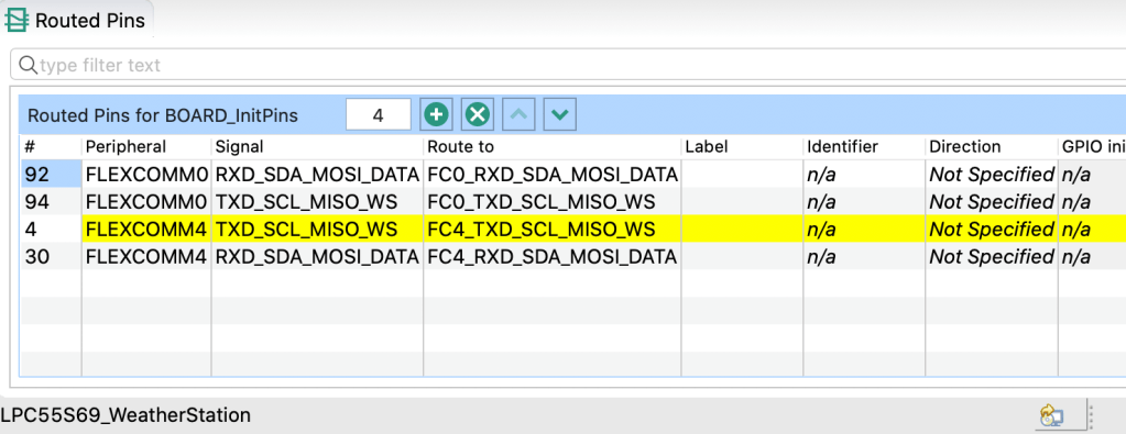
Follow the same procedure to route PIO1_21 for function FC4_SDA. That’s already done in the screen-grab above, and so I’m ready to move to the final, Peripherals Config tool.
PERIPHERALS CONFIG
Use the Peripherals icon to switch to the Peripherals perspective:
The Peripherals Config tool identifies that we’ve set up the pads/pins for FlexComm4 to be used as I2C. But we have not yet set up the I2C peripheral, and so the tool reports a Warning (there is also a warning for the default console UART on FC0 but we can ignore this):
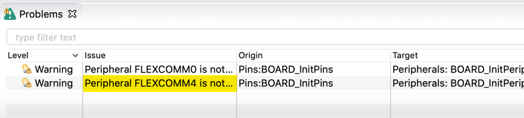
There is a very simple fix, proposed by the tool. Select the FC4 warning line, and right-click to bring up a context menu:
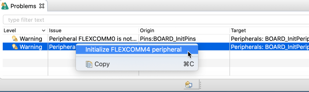
Selecting “Initialize FLEXCOMM4 peripheral” opens a dialog where we can select the desired function for FlexComm4… in this case we want I2C configuration. So we select I2C and click [OK]:

The Peripherals Config tool displays the Flexcomm Interface I2C configuration screen. This shows all of the ‘top level’ settings for the I2 C module. We have one change to make: we will use the Mode named “Transfer”. At the Mode dropdown box, select “Transfer” and note that further settings are enabled/displayed.
I promise you, that is all we need to do. Configuration is now complete for I2C on the OKdo E1 board. We can click “Update Code” at the top of the screen to generate all of the necessary configuration code, accept the changes, and return to the C/C++ Develop perspective.
SOFTWARE…
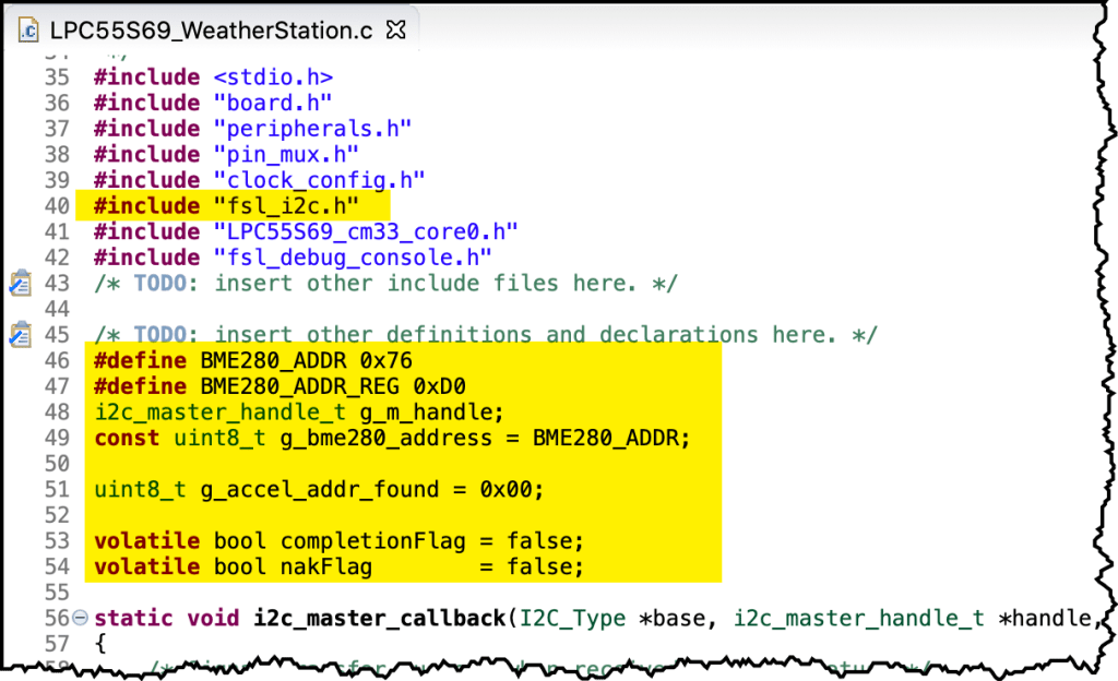
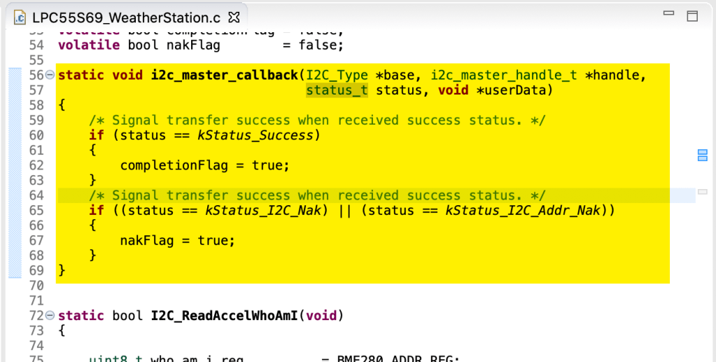
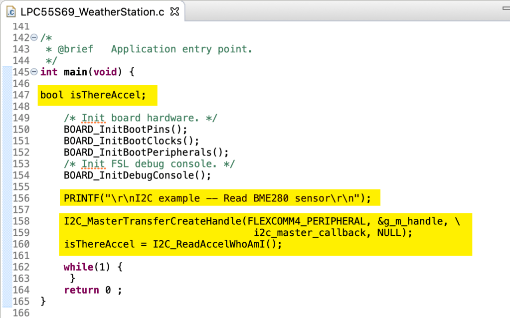
We do (of course) need to write some software to make the Bosch BME280 sensor come alive. You can refer to my YouTube video for this tutorial to see the software in action, but here is a quick summary of the changes, and the file is here. All edits are in the “C” source module named LPC55S69-WeatherStation.c that the new project wizard created:
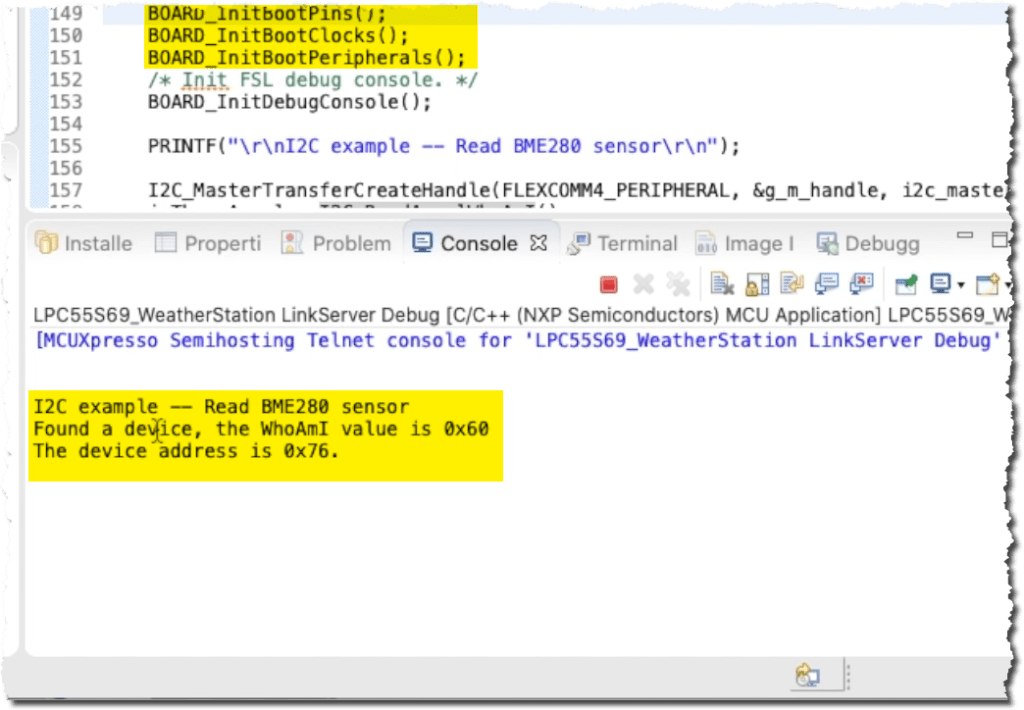
That should all compile and download to the board. Assuming that you connected the OKdo E1 board up to your sensor board, this is the output you’ll get from semi-hosting console view:
The tools make it look quite hard, but once you’ve used them, it all becomes obvious and efficient. In my online video tutorial I go through the steps in about 10 minutes. You can watch it here:
Next time we’ll read some more data from the BME280 sensor over I2C and start to get some real environmental data into my Weather Station. See you then, and feel free to let me know how you get on!

Pingback: MCUXpresso SDK Tutorial – using I2C Driver on OKdo E1 board | MCU on Eclipse