Clocks. I’ve always found the clock setting of a microcontroller one of the hardest things to get right during my embedded career. If I re-use the clocks setup from the development board it is easy. But if the development board runs from a crystal and I want to use the free-running internal clock, or if I change to a different frequency crystal (and keep the same PLL output frequency) it always gets difficult. To be honest I’ve developed some projects early in my career and never been 100% certain at what frequency the core, flash and peripherals are running.
That’s not good.
The Config Tools within the MCUXpresso brand have greatly simplified setting up the pins, clocks, peripherals (and next week – Trusted Execution Environment 🙂 ) on NXP microcontrollers. So I’m going to quickly show you how to set up 3 different clock arrangements, and output the main clock to an output pin named CLK_OUT.
I’m going to introduce embeddedpro® Axiom #1 – Every embedded project must enable the clock-out pin and measure the frequency of the internal clocks.
And here is embeddedpro® Axiom #2 – Every embedded project must DISABLE the clock-out pin before releasing production software, and before EMI testing. You don’t want a hopelessly mismatched 96MHz antenna on your board, do you?
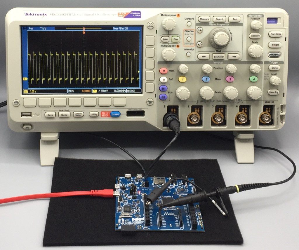
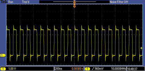
I’ve split the video into 2 parts this week. A short introduction video – 4 Using the Clocks Config Tool from MCUXpresso – theory helps us multiplex the CLKOUT signal onto a suitable output pin (PIO0_16) and identify a convenient location on the LPC55S69-EVK where we can measure the CLKOUT signal with a scope. It is most convenient to monitor the CLKOUT signal on Mikroe connector P23 pin 1. There is quite a ground loop and the scope traces below show some over/undershoot but we can determine the clock frequencies without any trouble.
The main, longer video is 4 Using the Clocks Config Tool from MCUXpresso – practical and creates a new MCUXpresso IDE project, configures the CLKOUT pin and then uses the Clocks Config tool to run the LPC55S69 from three different clock sources:
- the internal free-running oscillator (12MHz)
- the internal free-running oscillator (fast 96MHz)
- the internal PLL with external reference from Y2 16 MHz crystal.
When scoping the CLKOUT pin we can measure the main clock for the microcontroller. Since 96MHz is a little high I divided it down by 96 to make a nominal 1MHz, and I divided the 100MHz from the PLL by 10. These divisions are made with the CLKOUTDIV register in the SYSCON. Note that the frequency of the two free-running oscillators are approximately 12 MHz and 96-or-1 MHz (since these are RC relaxation oscillators onchip), whilst the divided-down 10 MHz from the PLL is a precise frequency.


As always you can find the videos in my channel on YouTube (search for embeddedpro) or watch them here:
And you really must make a note to come back next Monday when we’ll really get into details with the TrustZone® security extension for the Cortex® M33 core. That’s what we are all waiting for!!! Bye for now.

Can we configure each clock CPU, meaning, can we have, e.g., CPU0 running in a lower frequency than CPU1?
LikeLike