
This article is about a project I have started back in January 2018. As for many of my projects, it took longer than anticipated.But now it is working, and the result is looking very good: a DIY automated pick and place machine to place parts on circuit boards. In the age of cheap PCBs, that machine closes the gap for small series of boards which have to be populated in a time consuming way otherwise.
OpenPnP Pick&Place Machine
Outline
This DIY machine can populate circuit boards with SMD/SMT parts. If you are wondering, what this is: it is about putting Surface Mounted Devices (SMD) on a Printed Circuit Board (PCB). I gave a talk at the Embedded Computing Conference 2018 on this subject (ECC18 Styger – PickAndPlace mit OpenPnP).
The following videos give an overview about the current state of that machine:
The motivation of building such a machine is that at the university we are populating boards by hand:
Solder gets placed on the boards (stencils are rarely used):
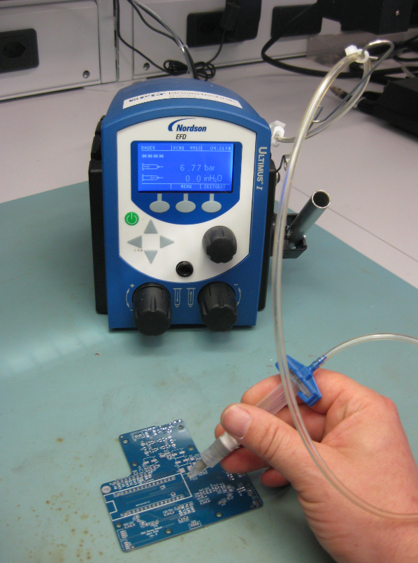
Applying solder
Solder paste on PCB
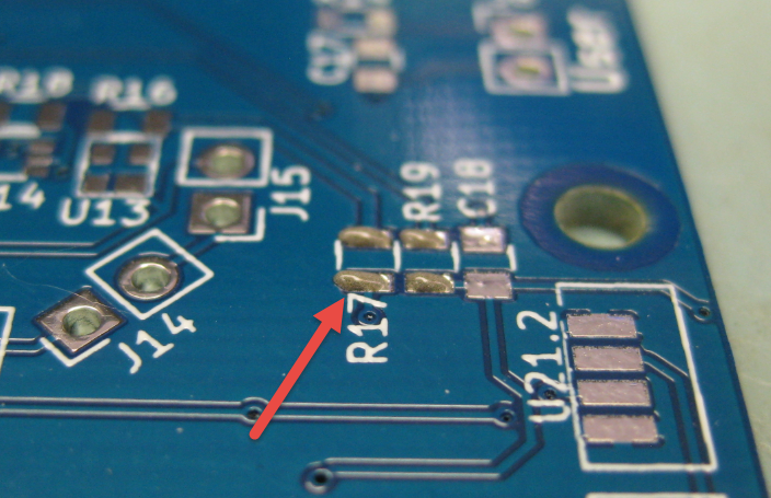
Then parts get placed on the boards

manual placing
We do have as well vision support for the manual placing:

manual placing with vision

Resistors placed on PCB
And finally they run through a reflow oven:
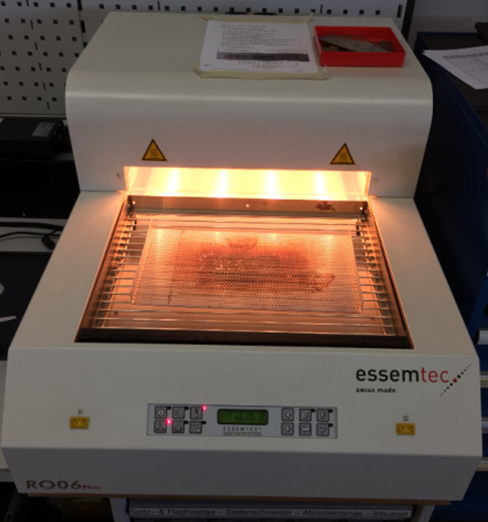
Reflow Oven
That’s all working fine. The problem is that this all takes a lot of time. Doing it for one board is one thing, but doing it for 10-50 boards takes too much time. Clearly, for mor than 50 or 100 boards, outsourcing is the logical choice. But for a few boards as we usually have to do, outsourcing is not the best option as it is expensive and takes a lot of time too.
What I wanted is a machine to automate the manual placing of components. Such a machine is called a ‘Pick and Place’ machine: it picks parts and places them on a PCB.
DIY Pick & Place Maschine: OpenPnP
When searching for such Pick&Place machines, I stumbled over the OpenPnP project at http://openpnp.org/: A open source community and project which builds such machines. So I thought: why not building one myself too? And here we go :-).
OpenPnP offers a framework to run such a machine. They have guides and tutorials how to build such a machine. And it is up to you how you build it and what features get added. I did not want to build the fastest or the cheapest machine: my goal was to keep the hardware costs below $1000, and that the machine is able to place parts down to the 0402 size.

SMD Sizes
All the software and BOM are available on GitHub (see links section at the end of this article).
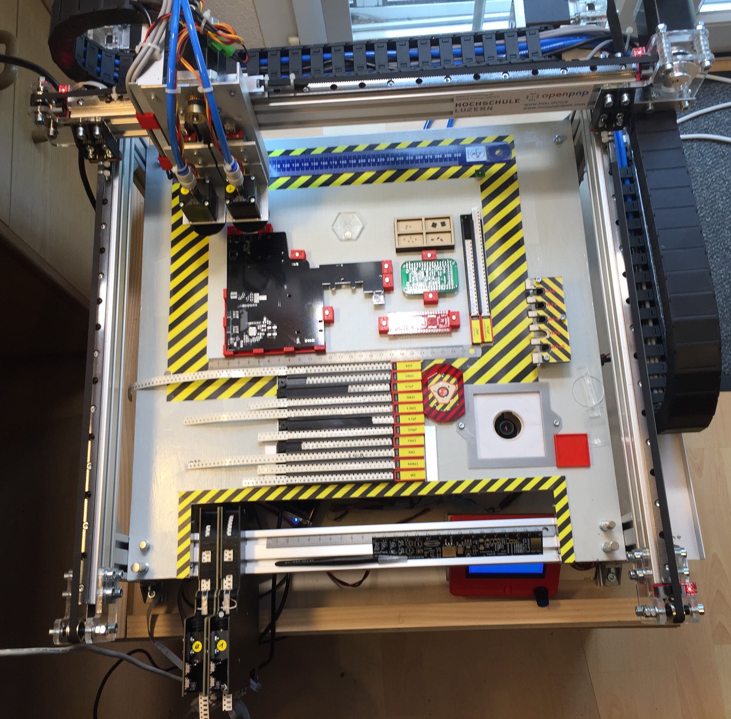
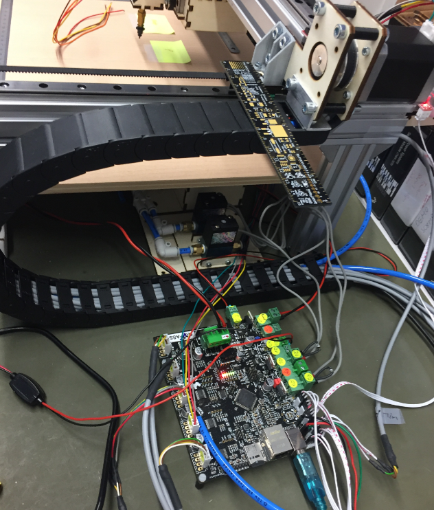
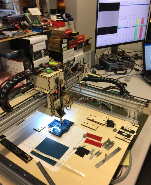
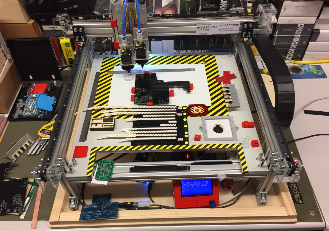
The machine uses 24V stepper motors for X, Y and Z axis. Two smaller stepper motors on the head (C1, C2) can be rotated. Attached to the head is a down-looking camera.
Integrated in the work area are nozzle changers, a bottom camera and different feeders.
Under the base plate all the other electronics (solenoid, pump, USB Hub, feeder and controller board with LCD and power supply.
CAD (KiCAD, Altium, Eagle) data is loaded on a host PC running OpenPnP.
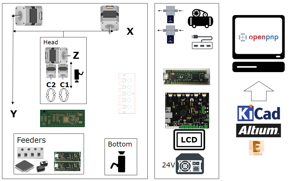
System Overview
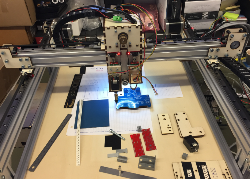
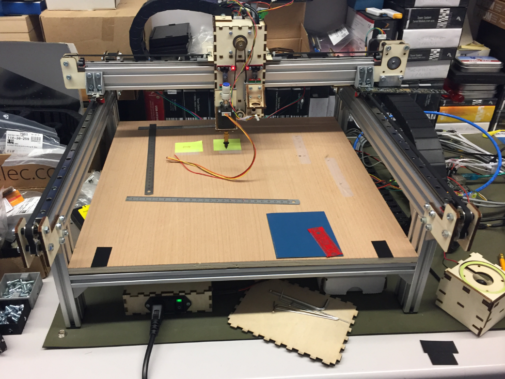
Below are pictures of the machine under construction with some details. I hope this gives you ideas and an inspiration to build your own machine.
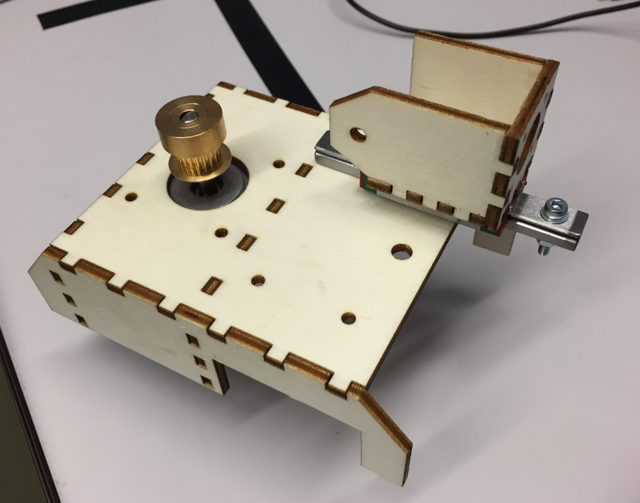
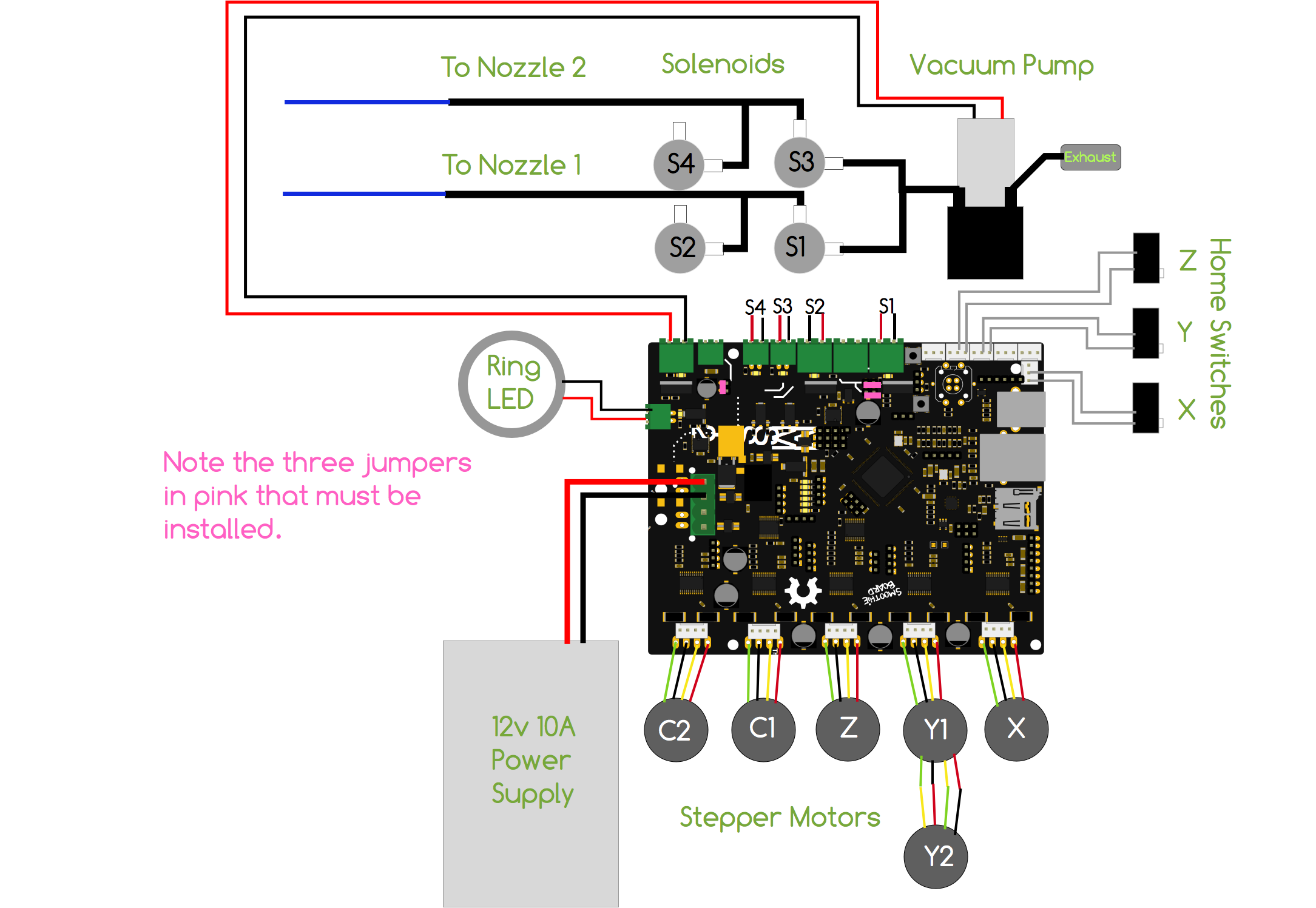
Microcontroller
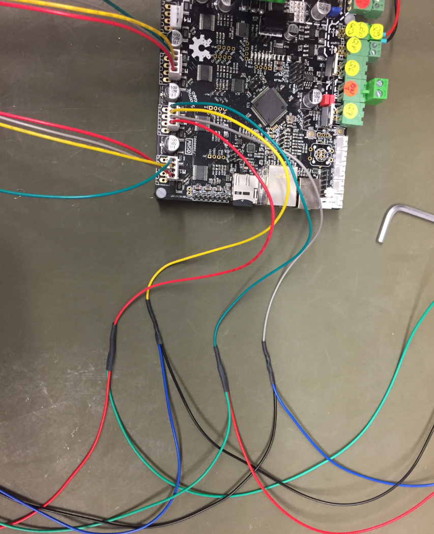
The heart of the machine is the NXP LPC1769 on the Smoothieboard:

NXP LPC1769
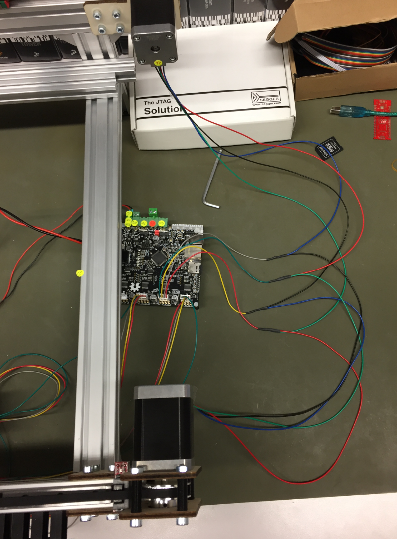
It is responsible for all the sensors and drives all the motors. The picture below shows first tests with a stepper motor:
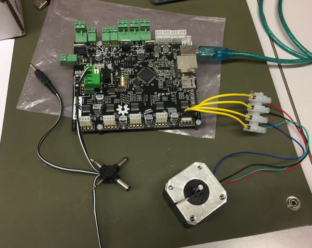
first stepper
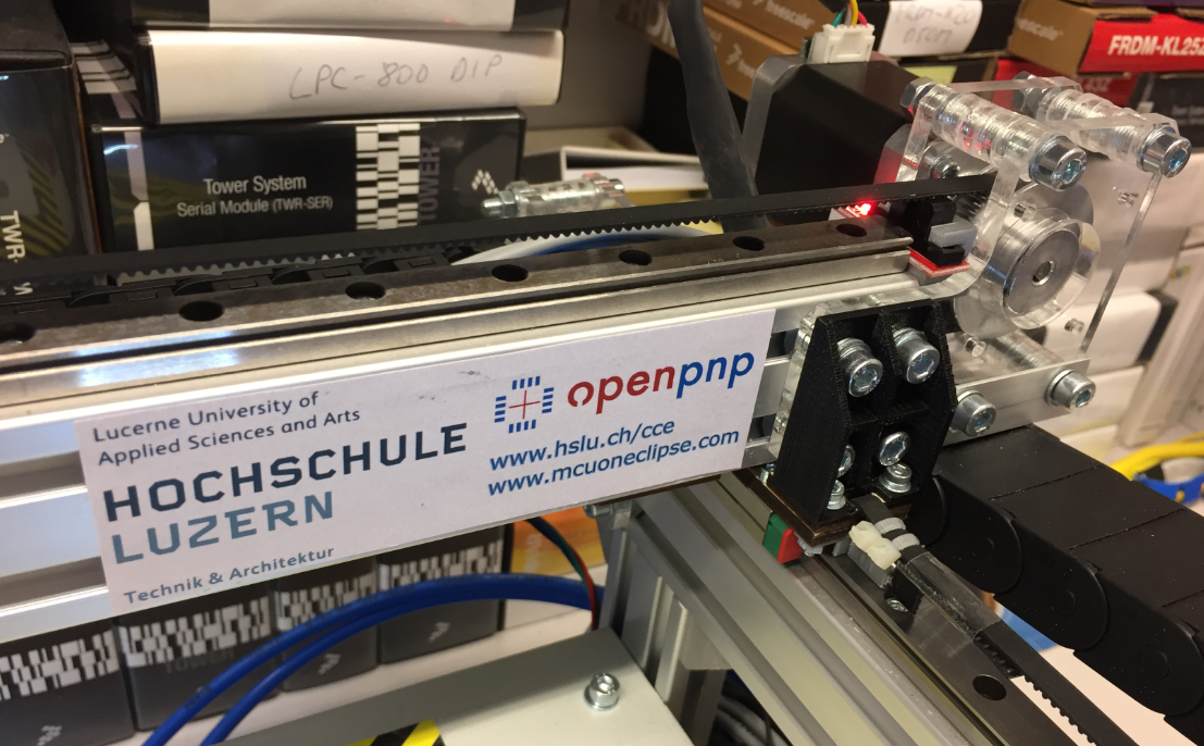
Frame
The frame is constructed with 20×20 and 20×40 standard aluminum extrusion profiles:
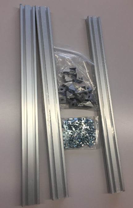
Aluminium
The profiles allow an easy construction of the frame.

Aluminium Frame Construction
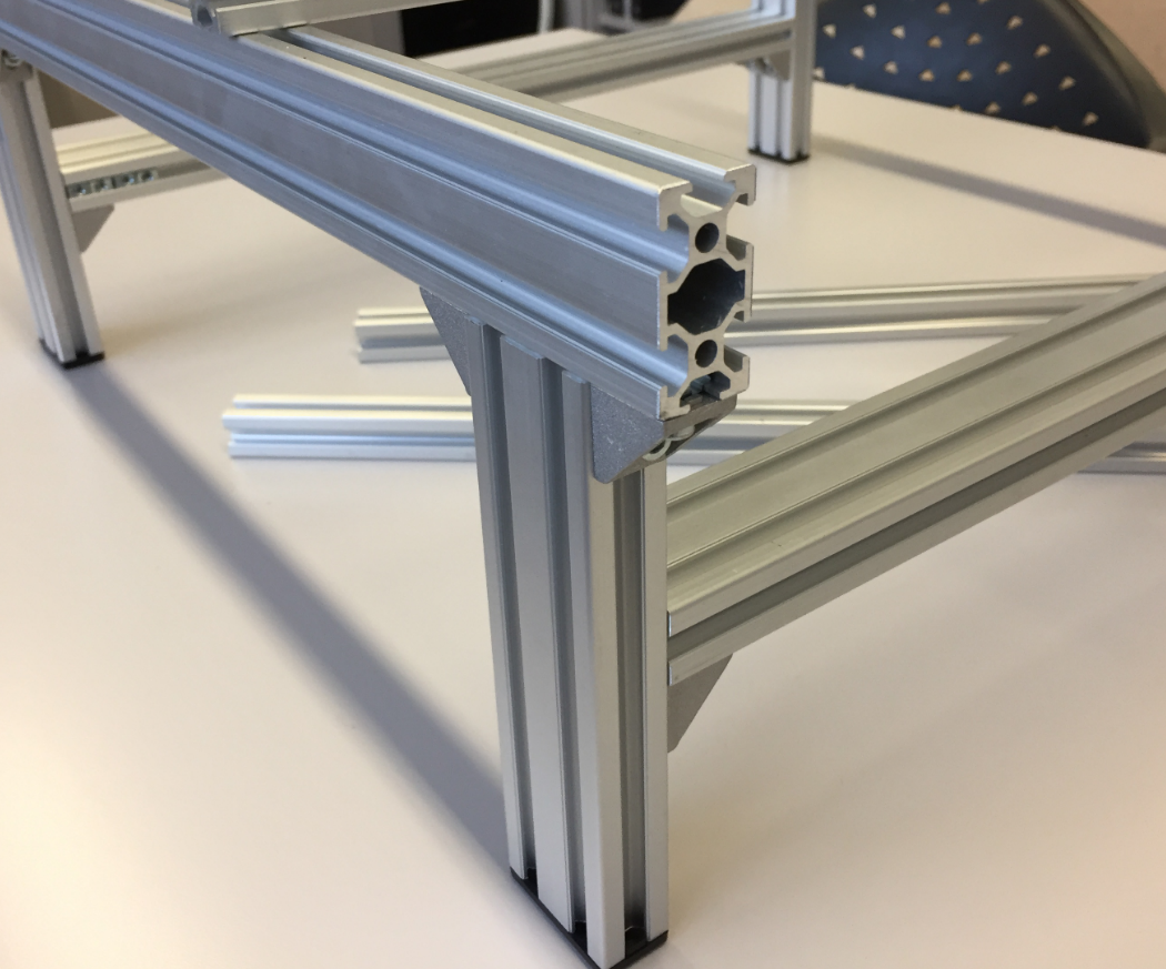
2040 Profiles
Rails
The linear rails arrived very well oiled and in good shape.
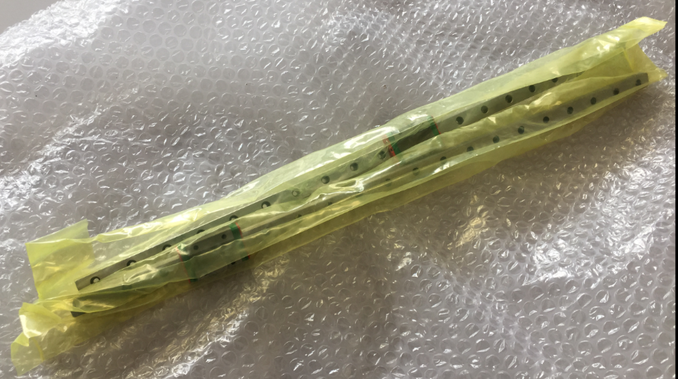
Linear Rails arrived
The rails get attached to the top of the frame:

Rail mounted on frame
It has been an iterative process, and many parts first have been built with a laser cutter and plywood. Below is a picture of an early version:
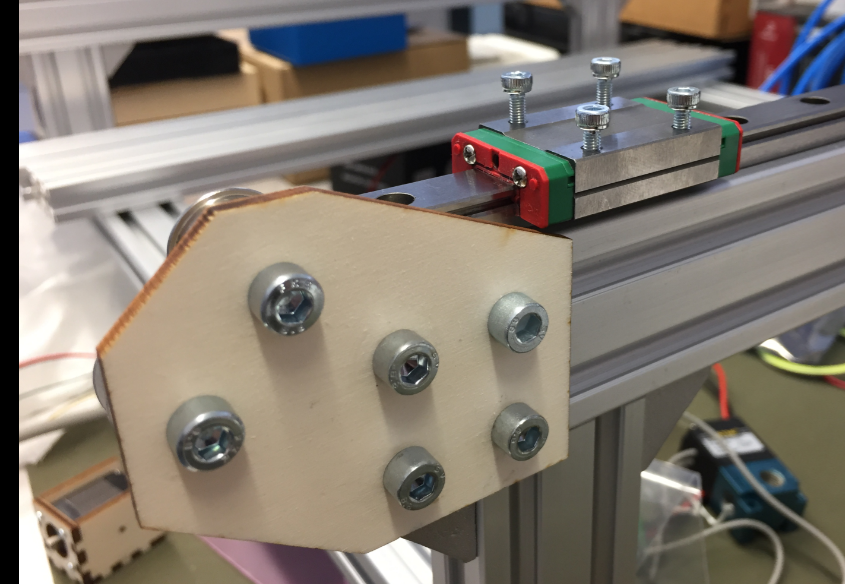
Rail with end bracket
Vacuum Pump
Actuators in the system are 24V. Below is the diaphragm vacuum pump used for the nozzles:
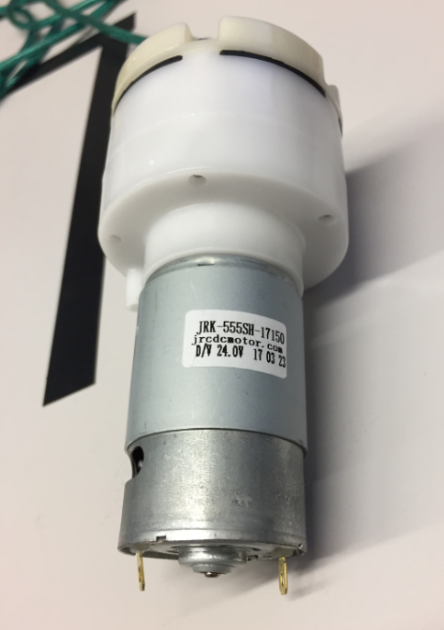
24V Vacuum Pump
Terminals of the pump:

Vacuum Pump Connectors
The pump together with the two high-speed solenoid on a base plate. To reduce noise, the pump has been placed into a box standing on anti-vibration feet:
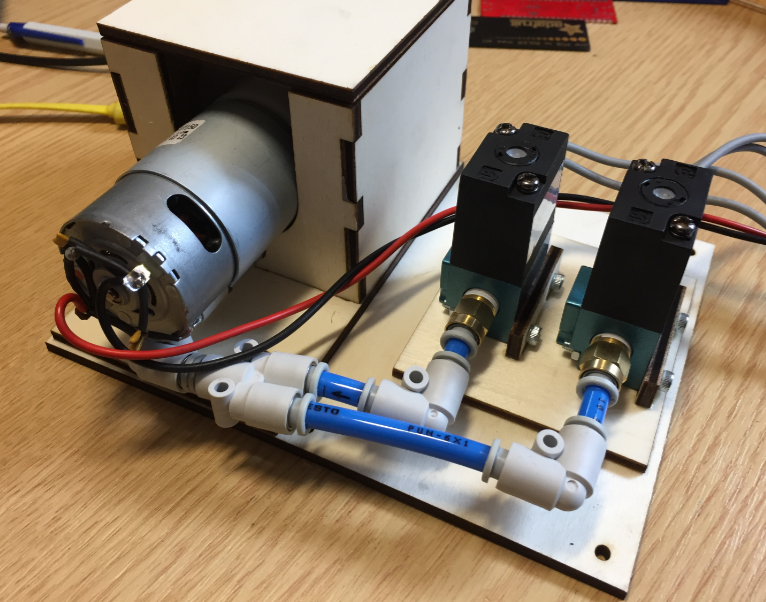
Pump with enclosure

Pump Top View
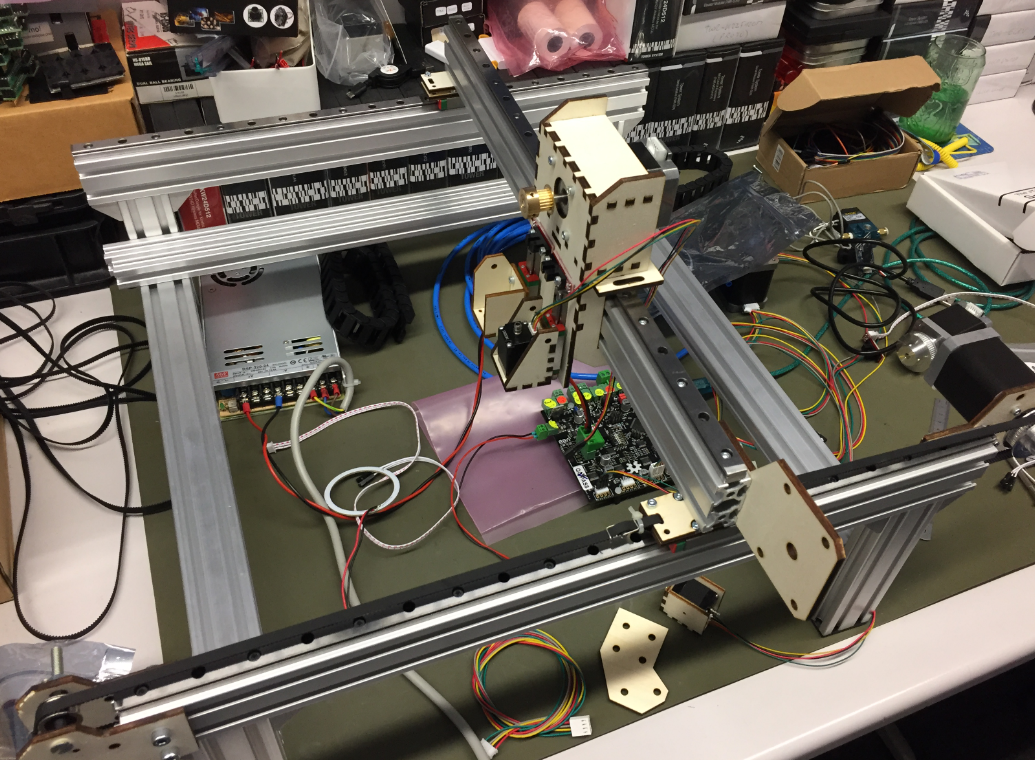
Below a first test with three stepper motors:

Bench
Power Supply
For the 24V 13.4A Power supply I added an on-off switch with integrated fuse holder:

Power Supply with On-Off Switch
Flyback Diodes
As flyback diodes for the pump and solenoids I used the Vishay BYV27-200-TAP:

Protection Diodes
Vacuum Valves
I’m using the STNC TM-06 high frequency valve (24VDC) with 1/8″ pipe connectors:

STNC TM-06 Valve
Below how they are connected to the board with the flyback diodes mounted to the connectors:
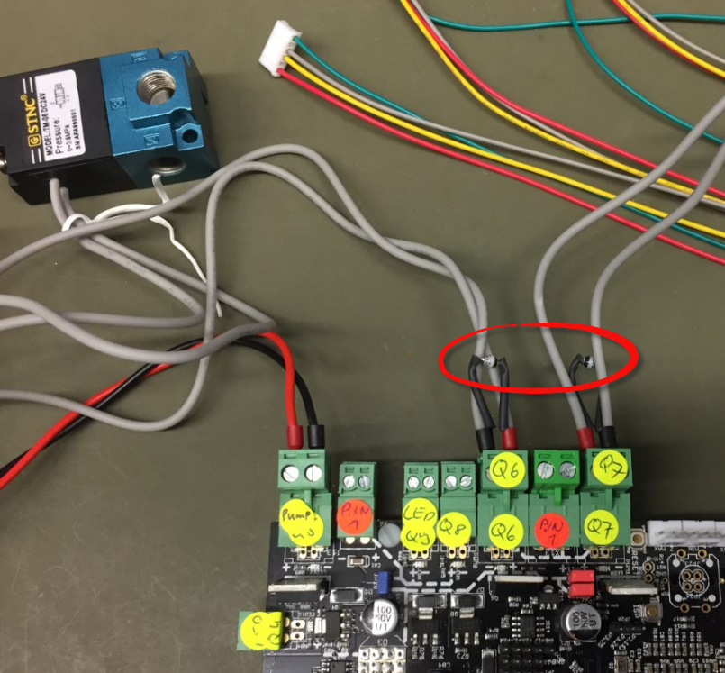
Protection Diodes for Solenoids
For example the M813 G-Gode turns it ON (2-1 connected), and M812 turns it OFF (2-3 connected). The image below shows the air flow:

STNC Directions
That means the vacuum pump will be on connection 1 and the nozzle on connection 2, with connection 3 used to release the vacuum.
End Stops
The total of 6 end stops are optical ones:

End Stops
The first (not ideal) way to mount the end stops:
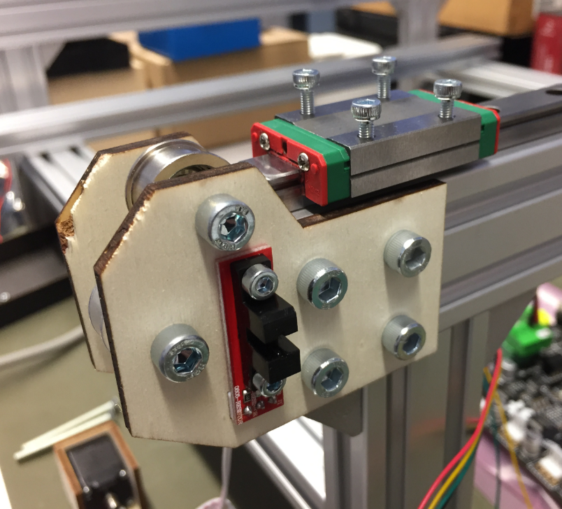
First way for endstops
Second version of end stop mounting with 3D printed holder:

3D Printed End Stop Holder

3D Printed End Stop Holder back side
Mounted End Stop

3D Printed End Stop Parts
3D printing end stop blades:
3D Printing End stop Blades
Mounted end stopper blade:

Mounted End Stopper Blade
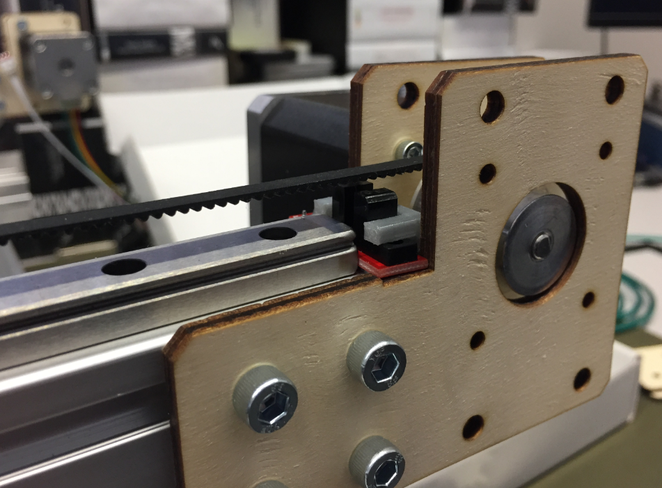
In a next step lowered the end stop position:

Lowered End Stop Position

Belt and Endstop
Pick and Place Head
Very first version of the head:
First Pick Head
Holder for the pick stepper motor:

Holder for the Pick Stepper Motor
Rails for the pick head steppers:

Pick Head Rails
Frame with first pick head:
Frame with first pick head
Pick head with end stops:

Pick Head with End Stops
Because the X axis was not rigid enough, 3D printed brackets were added:

3D Printed Bracket
X-Y-Rail

Mounting Bracket for X-Y Rail
T-Nuts on X-Y Rail:

T-Nuts on X-Y Rail
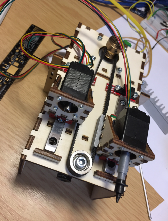
Y Steppers
Two stepper motors wired together are driving the Y axis. It works, but I would not recommend that approach: better use a single motor with an extended shaft and coupling.
Wiring of Y motors
Y Stepper Wiring
Laser cutting the motor and pulley brackets:
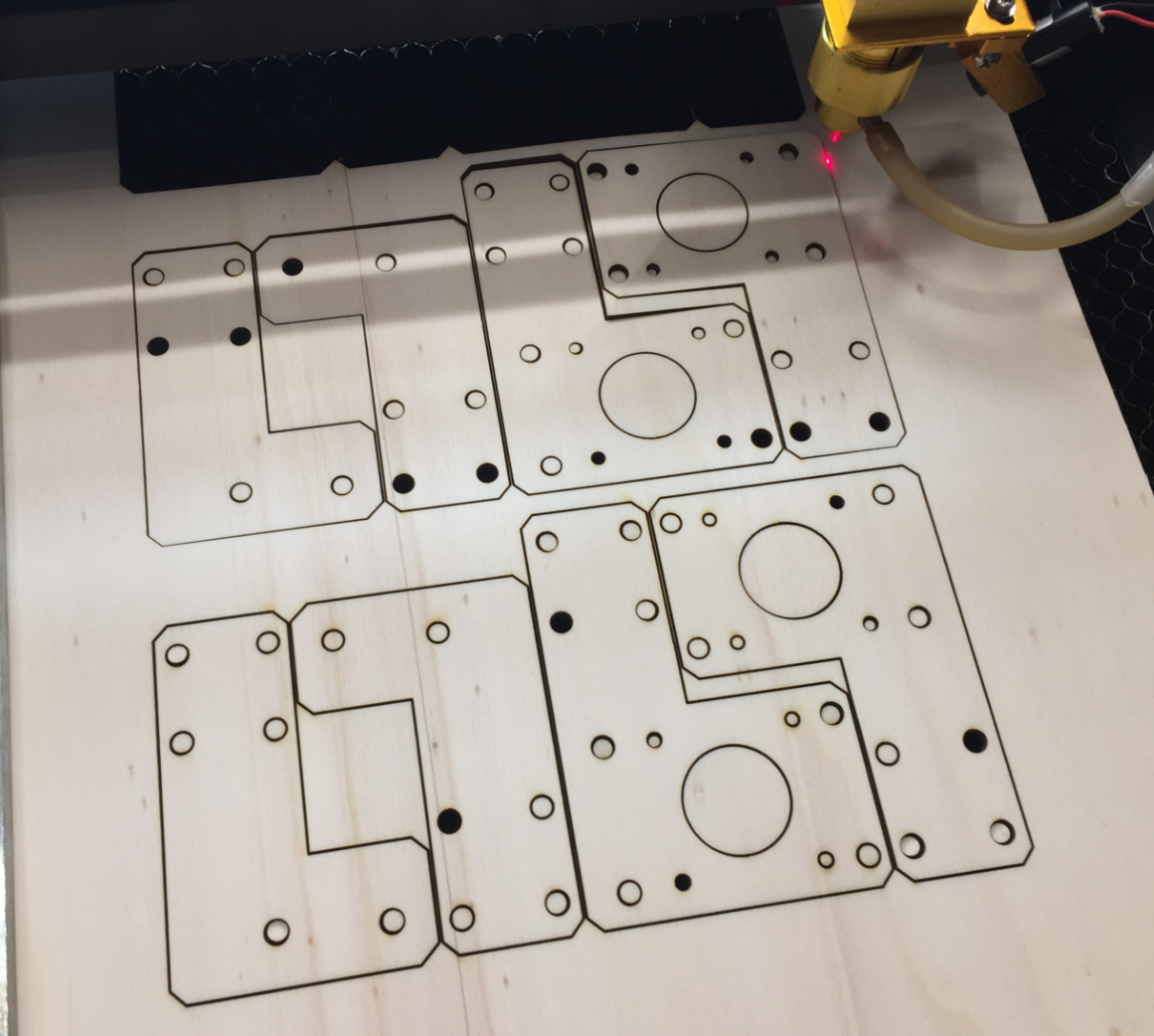
Laser Cutting Motor Brackets
Of course it was an iterative process, and many design ideas did not end up in the final machine. The good thing with plywood is that it is cheap and is easy to construct with it.
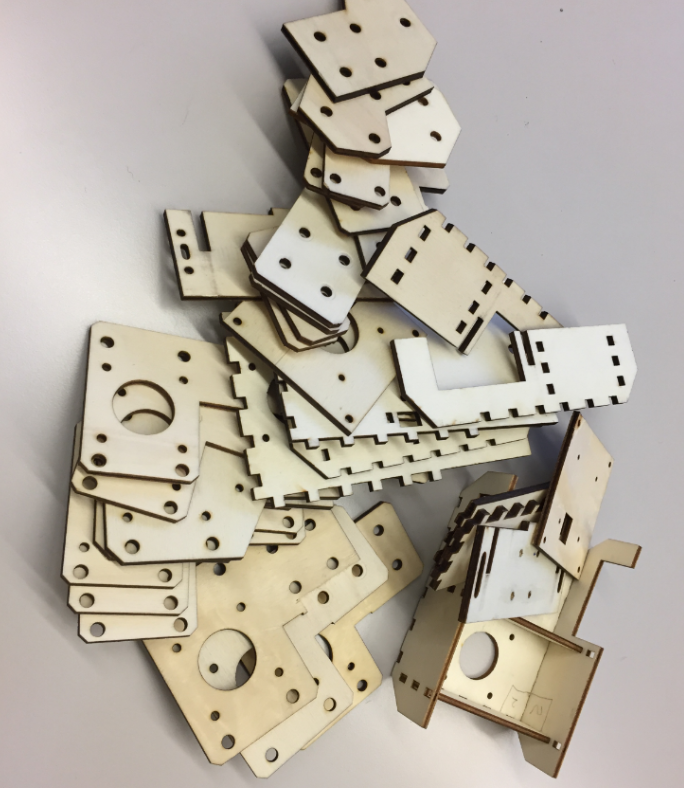
Pile of plywood
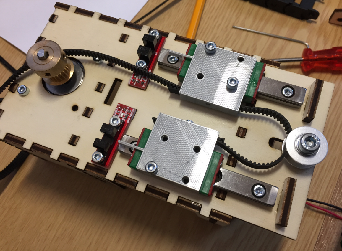
Second Pick Head Design
The second version of the pick head was more compact and easier to attach to the linear rail.
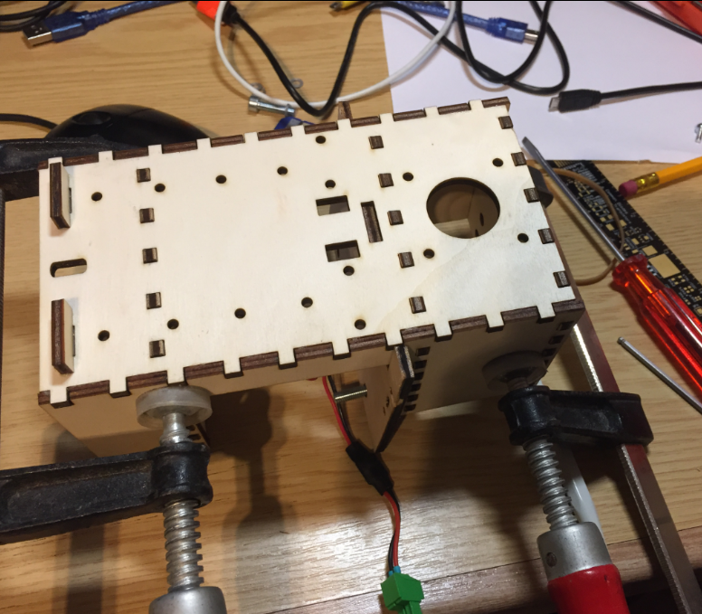
Assembling the Pick Head
Below the head attached to the X axis:

2nd Pick Head
Pick Head 2nd Version
Below an early version of the head with no cable chains attached:

Head without cable chains
I used 3D printed parts to attach the heads with the Z axis belt:
Z-Axis Belt with 3D printed parts
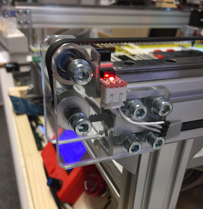
The belt is attached to the linear rails using a press-fit connection, and the connector acts as an end stop the same time:

Press-Fit Belt Holder
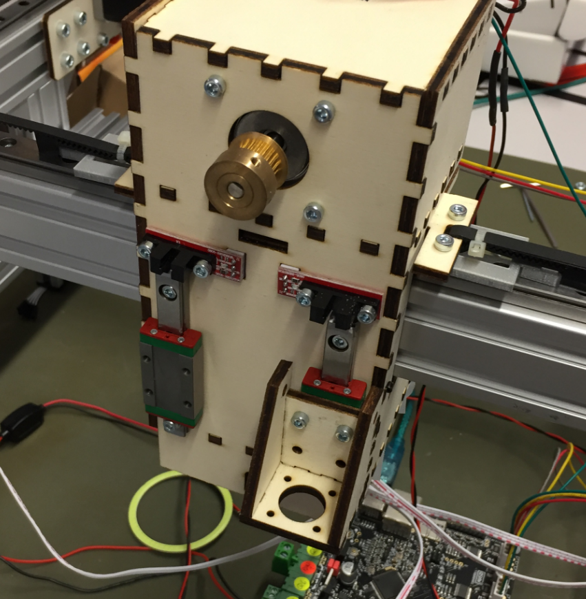
Here with the rails, belt and endstop mounted:
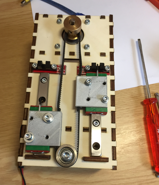
Head Rails and Endstops mounted
Here the head with the pick heads:
Pick Heads
Downlooking Camera
Below an early design of the downlooking camera integrated into the bottom of the head:

First version of downlooking camera
First down camera and light tests:
First Camera Tests
First Camara and LED ring holder:
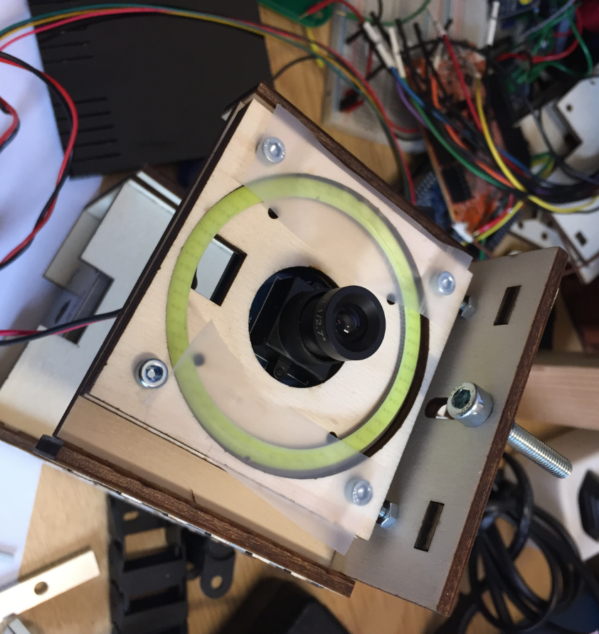
First Camera Holder
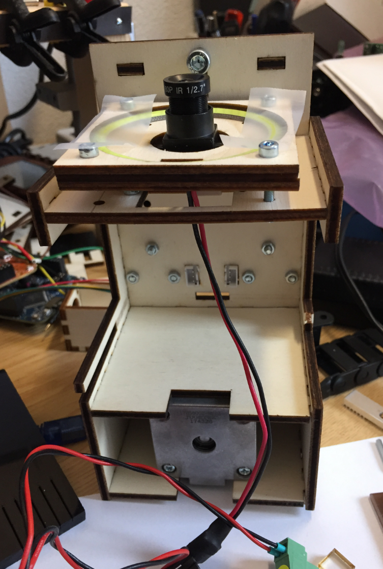
Head with Camera Holder
A plexiglass with a sheet of whiter paper acts as diffuser:

LED Ring diffuser
Pick heads with downlooking camera:

Pick Heads with downlooking camera
Mounted head with first cable chains:
PnP Machine
Metal Pick Head
The next iteration oft the pick&place had is a version built with aluminium profiles. The first step was to use aluminium profiles for the head mounts:
Aluminium Head mounts

Aluminium Motor Mounts
Then the head backplane has been built with aluminium profiles:

Aluminium Profile Pick Head
That way the head was more sturdy than the one made of plywood.

Aluminium Profile Head
Below with the hollow shaft stepper motors mounted, plus a cable chain for the end stops, LED ring and camera USB cable on the left:

Aluminium Profile Pick and Place Head

Machine with Metal Head
Nozzle Holder
Nozzle Holder, magnet holds the nozzle:

Nozzle in Holder

Nozzle and Nozzle Holder
Improved nozzle holder with 1.5 mm space between the plates and acrylic on the top:

Nozzle Holder with Acrylic
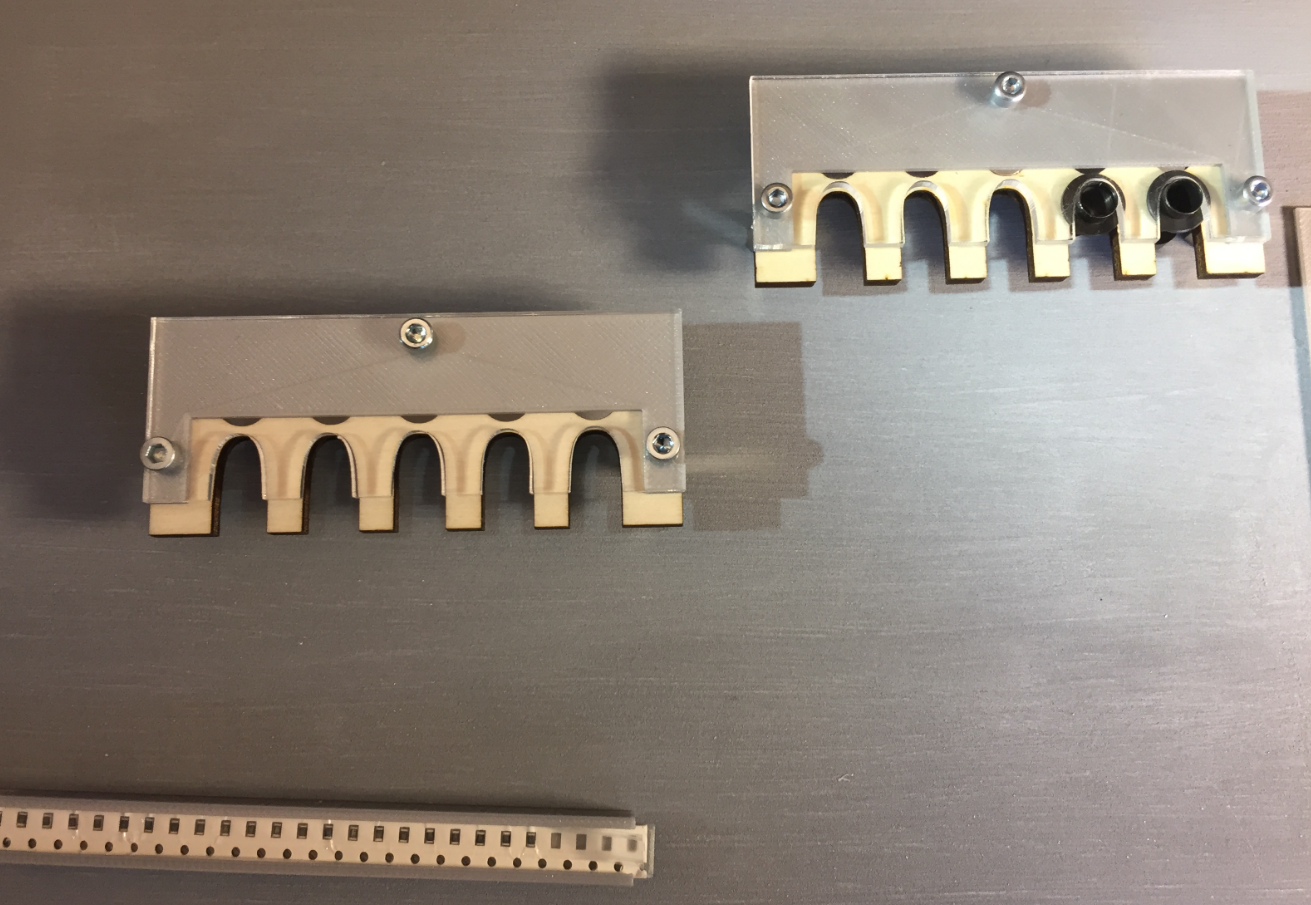
Nozzle Holders mounted on base plate
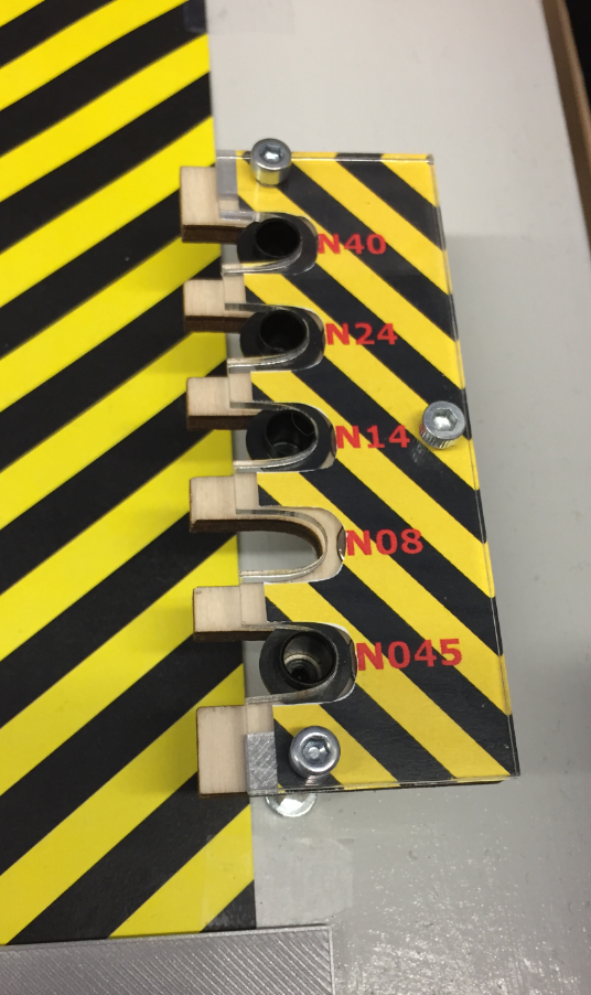
NozzleHolderLabel

Different Nozzles
Cut Tape Holder
See 3D Printed SMT Cut Tape Holder for more details.

SMD Strip Holder

Cover

Tape Holder with Magnets

Tape Holder 3D Model

SMD Tape Holder
Feeder
The automatic feeder is designed by Simon Huber. The goal was to create a feeder for SMD parts on rolls.
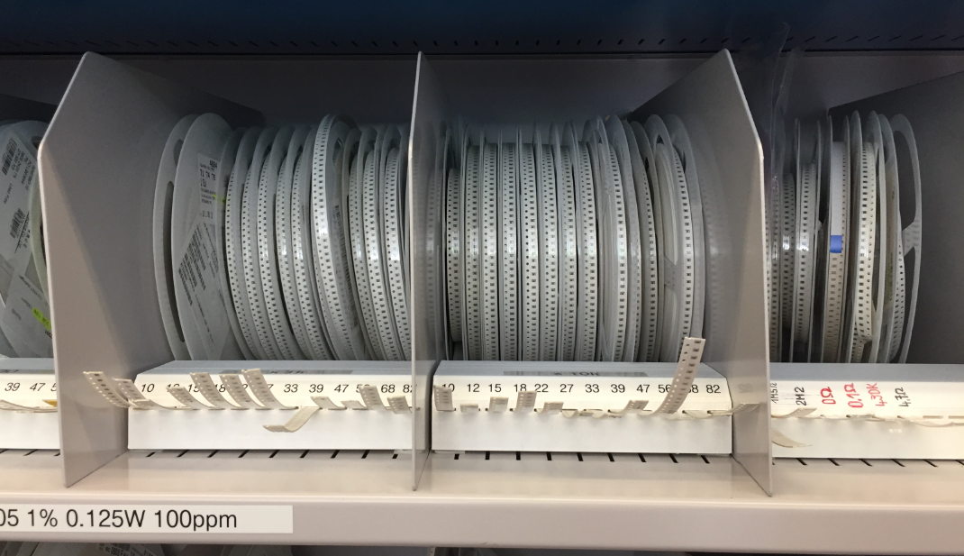
SMD Resistors
The feeder uses 3D printed parts:

3D Printed Feeder

Feeder with SMT Tape
Each feeder uses a NXP K20DX128 (ARM Cortex-M4) as the controller:

AutoFeeder
One DC motor moves the tape and one DC motor peels the cover:

Feeders removing cover
A tinyK20 (NXP K22FN512, ARM Cortex-M4) receives M-Codes from OpenPnP and passes them to all feeders:

tinyK22
The feeders are in a daisy chain, and the machine has space for up to 16 feeders.
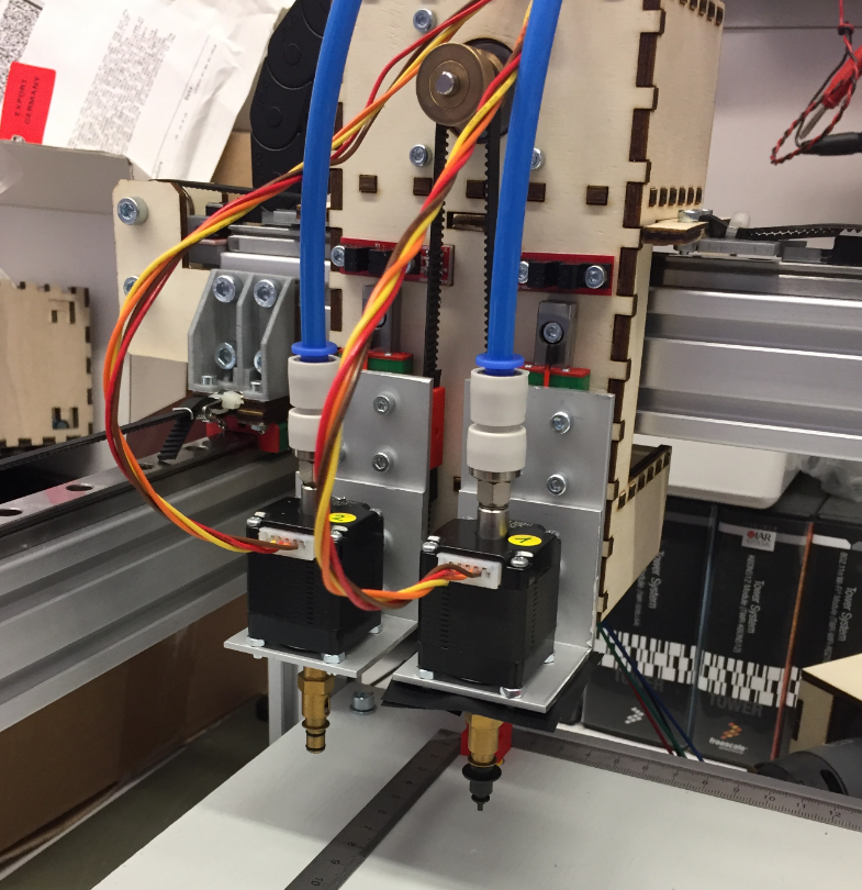
Nozzles
The first nozzle stepper motors did not work well. The M5 screw did not match the stepper motor hollow shaft. The designed adapter had too much wobble and was not usable.
First Pick Head with Nozzle Adapter
So I had to put aside the nice and small hollow shaft stepper motors. I ordered new (bigger) ones so I can easier attach the nozzle changes and a vacuum tube connector on the back. The new motors had on both sides an M5 screw so I can attach rotation tube adapters and attach easily the nozzle adapter.
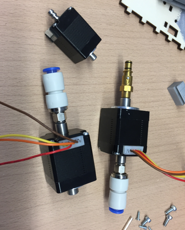
New Nozzle Stepper Motors
Because the motors were bigger, I had to create new motor holders:

New Nozzle Motor on the head
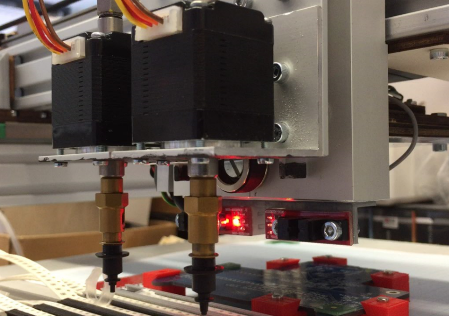
Pick Heads
Cable Chains
The first cable chains were too small to hold all the tubing and cables, so a new one has been installed.Below the machine with the first (too tiny) cable chains:
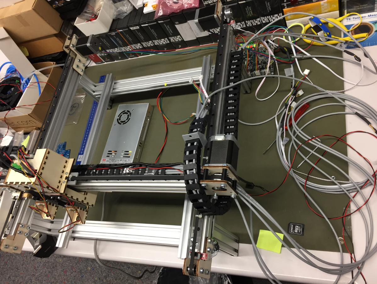
PnP Machine with small cable chains
Small cable chain attached to the head:

Small cable chain attached to the head

Machine with small cable chains

Machine with second version of head
New cable chains arrived:
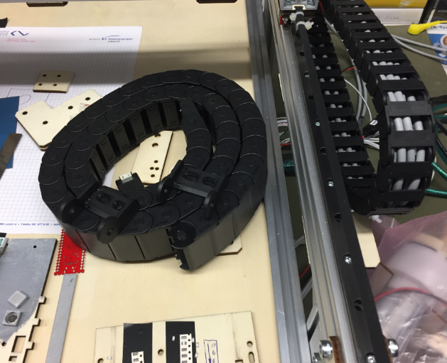
New Cable Chain arrived
That larger (40×15 mm) was able to keep all the cables and tubing.

Bigger Chain holds it all
Below with the new chain attached to the head:

Head with new cable chain

Cable Chain
Side View with Cable Chain
Base Plate
Machine with new base plate
The bottom plate with cutouts for the feeders and the bottom camera:
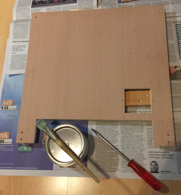
Base Plate ready for paint
It gets painted with three layers of magnetic paint:
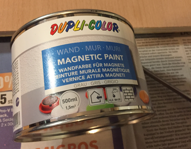
Magnetic Paint

Painted Base Plate with Magnetic Paint
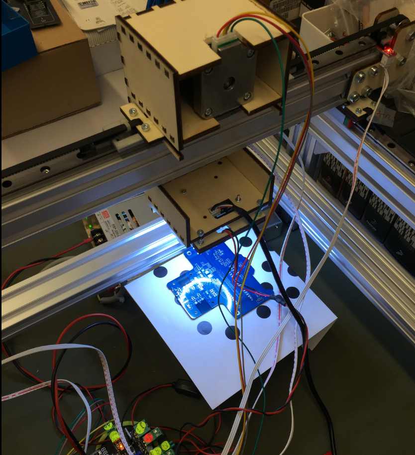
Bottom Camera
Laser Cutting the Enclosure for the Bottom Camera
Assembling the bottom camera enclosure:

Assembling bottom camera enclosure
Assembled bottom camera case:

Bottom Camera Enclosure
Testing the camera:

Testing the Bottom Camera
Up camera mounted into base plate:

Uplooking Camera (Bottom Vision) in Base Plate
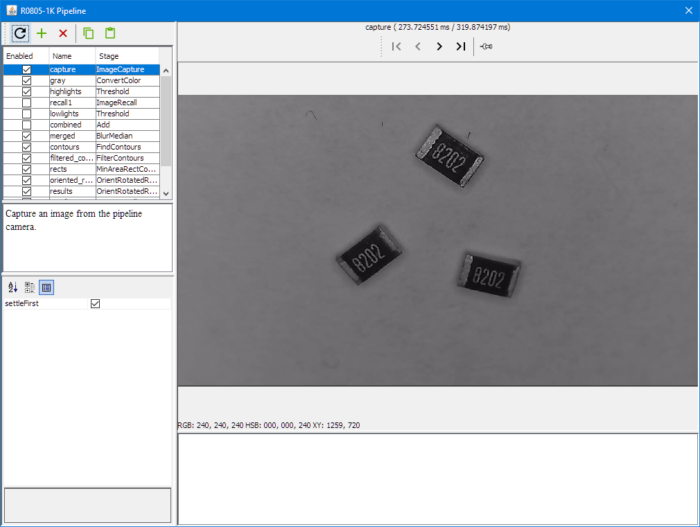
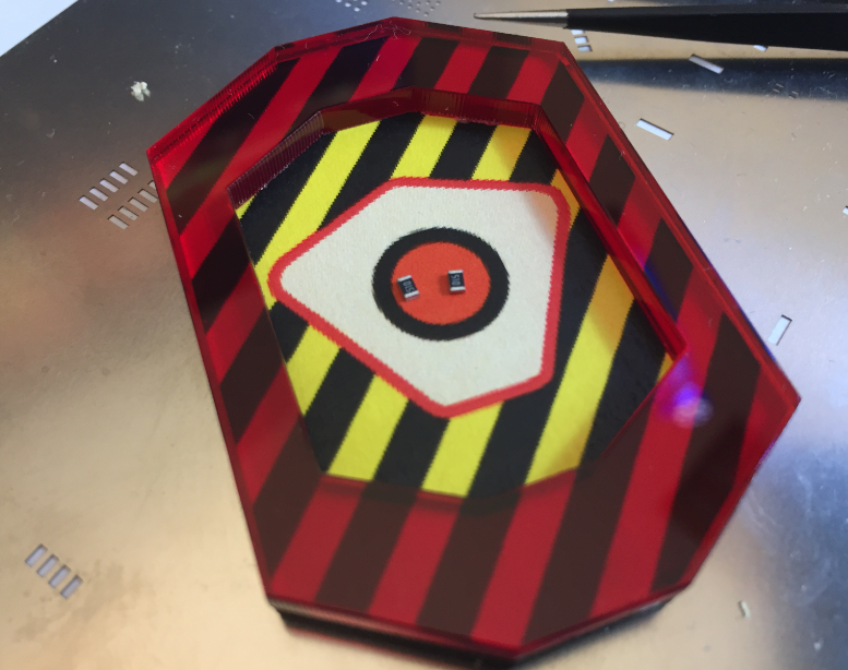
Bottom Vision
With the bottom camera, OpenPnP can move a part over the camera to correct angle and position with the vision system:

Bottom Vision Capture
It uses a vision pipeline, below with a blur filter applied:
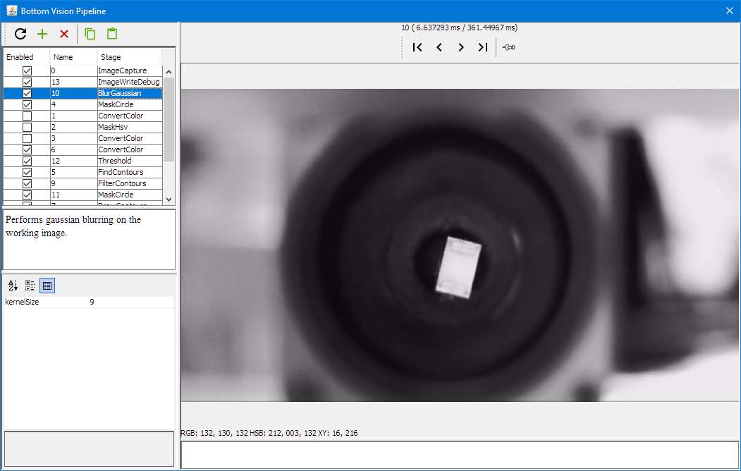
Bottom Vision Gaussian Blur
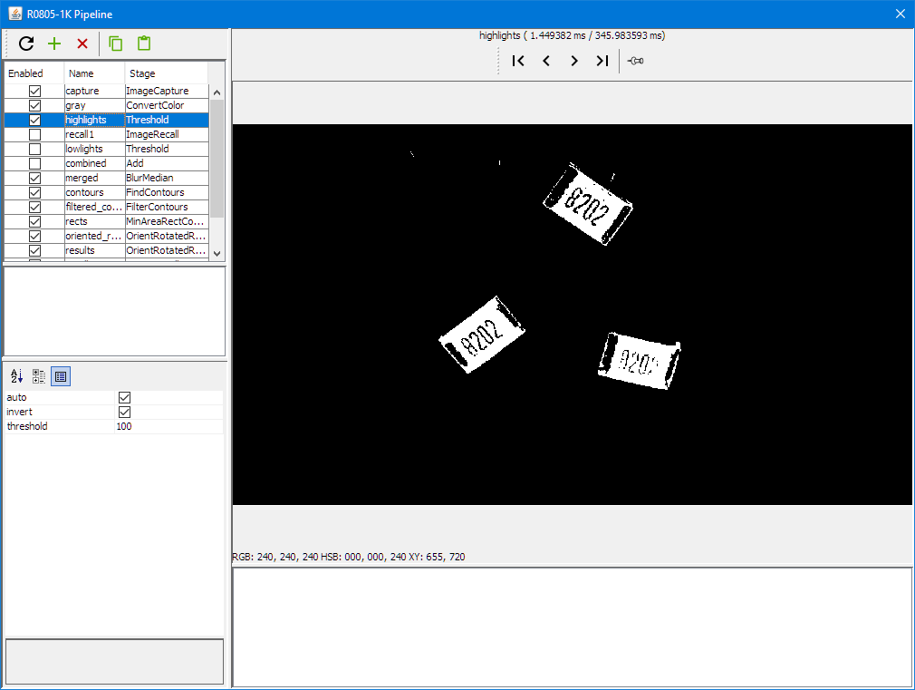
Masking:
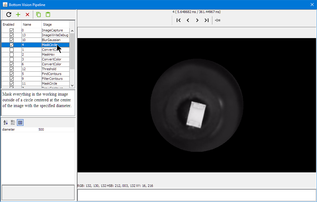
Bottom Vision Circle Mask
getting the part outline:

Bottom Vision Threshold
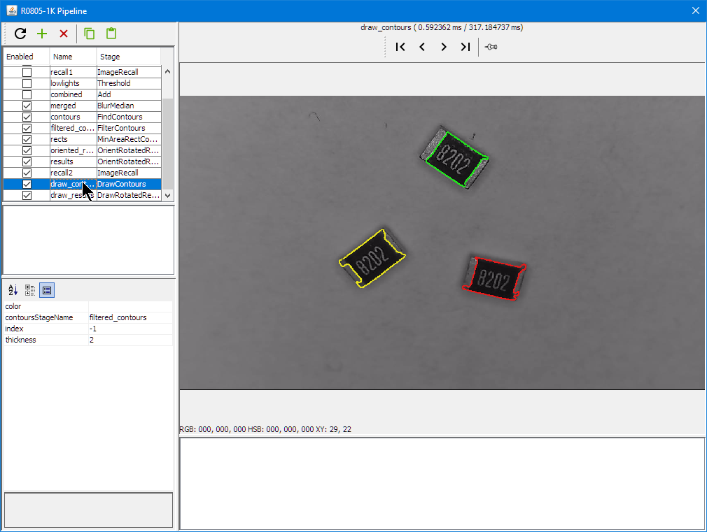
Getting the contours:

Bottom Vision Draw Contours
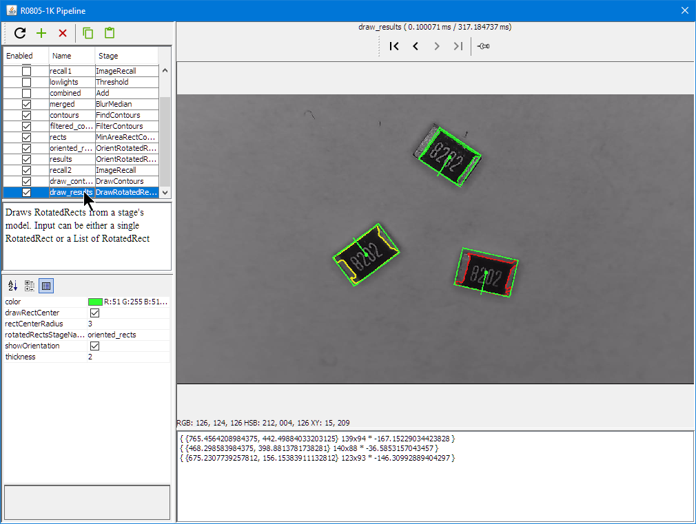
Detecting part position and angle:
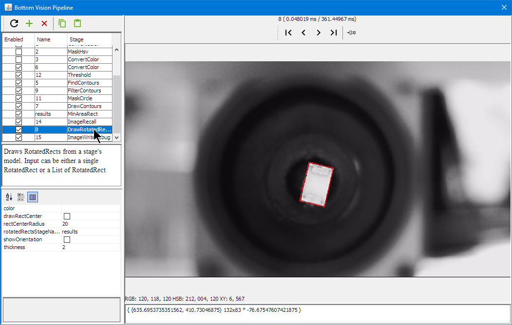
Bottom Vision Rotation Rectangle
OpenPnP includes a loose part feeder: parts can be put into a bin and the vision system can identify it:
LoosePartsFeeder 1
LoosePartsFeeder 2
LoosePartsFeeder 3
LoosePartsFeeder 4
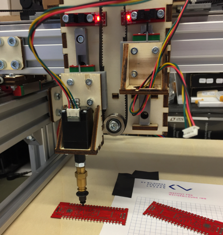
PCB Holder
As the top camera has rather small focus area, I need to keep the feeder pick (see “3D Printed SMT Cut Tape Holder“) height and the PCB surface on the same height. For this I have created 3D printed magnetic PCB board holders.

3D Printed PCB Holder with Red PCB

3D Printed PCB Holder
Graphic LCD
Similar as for my laser cutter (see “Upgrading a Laser Cutter with Cohesion3D Mini and LCD“) I added a graphics LCD to the board.

Machine with LCD Display
http://smoothieware.org/rrdglcdadapter describes the settings and installation of a graphics LCD on the Smoothieboard.
I decided to order an adapter board from 3DWare:

GLCD Adapter Board Top Side
Below the bottom side of the board:
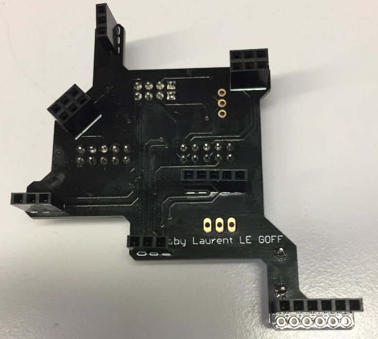
GLCD Adapter Board Bottom Side
Below how the adapter board is installed on the board:
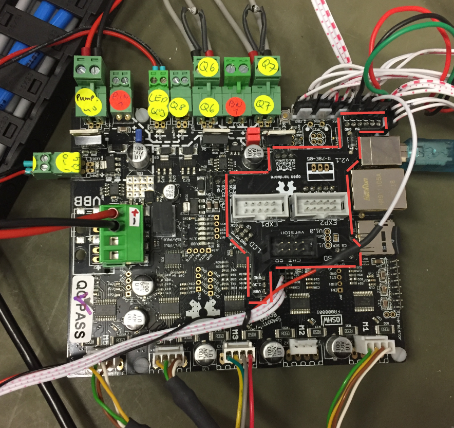
Location of GLCD Adapter on Smoothie
Below the display attached to the board and working :-):

Smoothie with GLCD
Below the (still messy) electronic parts on a base plate:
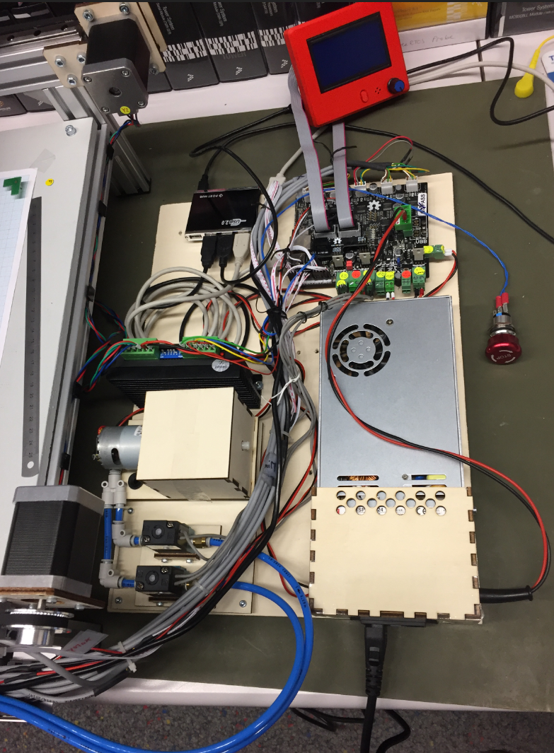
Electronics
Added to the display is an emergency stop button. Below the connection to the controller board:
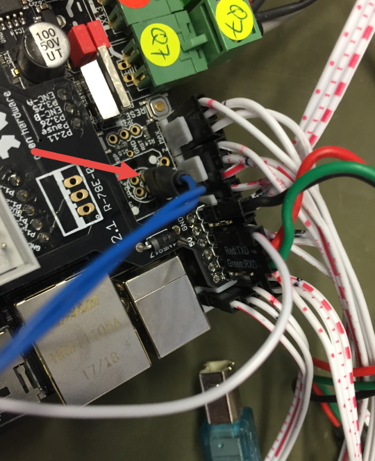
Emergency Stop Connection

LCD with Emergency Stop
OpenPnP Software
The OpenPnP software runs on the host PC.
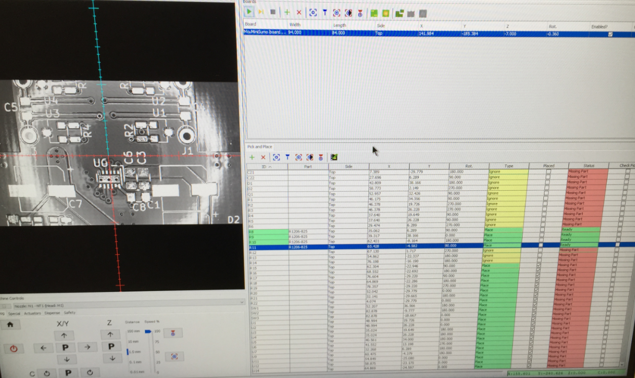
OpenPnP Software
The host PC does all the image processing and sends commands to the machine.
Running an OpenPnP Job
Drop Box
For bad parts or to drop parts, OpenPnP can use a dedicated ‘drop area’. for this I created a custom (laser cut) drop box: It uses 3mm red acrylic on the top:
PnP Drop Container
4mm plywood on the bottom with magnets so it sticks to the machine surface:

PnP Drop Container with magnets
Plexiglas Brackets
The motor and belt brackets originally were cut out of plywood: here I replaced the 4mm plywood with 5 mm laser-cut plexiglas ones which looks nicer :-):
Plexiglass PnP Bracket
X Axis with Plexiglas/PMMA motor bracket
The machine mounted on a 16mm plywood base plate:
Mounted on BasePlate
Summary
It has been a fun project, and the machine works well, but still needs some tuning. I plan to add a solder paste dispenser: that way, if no stencil is available, the machine can add the solder paste to the pads on the board. Another thing is to use pressure sensors to monitor the vacuum for each nozzle. And for the motor auto-feeder I would like to update the design. So there is always something to improve. Currently the machine can place around 500-600 parts per hour down to 0402 size. With this and little setup, we can run small board series successfully.
PS: a big “thank you!” to the OpenPnP community: without all their work and contributions, such a project would not have been possible.
Happy Picking 🙂
Links
- Files of my machine on GitHub: https://github.com/ErichStyger/McuOpenPnP_Machine
- Presentation at the Embedded Computing Conference 2018: http://www.swisst.net/files/swisstnet/de/dokumente/ECC/ECC18/Referate/3C2_Styger_HSLU.PDF
- 3D Printed SMT Cut Tape Holder
- Smoothieboard hardware on GitHub: https://github.com/Smoothieware/Smoothieboard
- Smoothieboard configuration options: http://smoothieware.org/configuration-options
- Smoothieboard supported G and M codes: http://smoothieware.org/supported-g-codes
- Smoothieboard extruder: http://smoothieware.github.io/Webif-pack/documentation/web/html/extruder.html
- LinuxCNC G-Code List: http://linuxcnc.org/docs/2.6/html/gcode/gcode.html#_g_code_quick_reference_table_a_id_quick_reference_table_a
- Reprap G-Code List: http://reprap.org/wiki/G-code
- STNC TM-06 24V valve: https://www.robotdigg.com/product/566/High-frequency-Solenoid-Valve-12-or-24VDC
- GLCD Adapter board: https://www.3dware.ch/Adapter-LCD-s-GLCD-f%C3%BCr-Smoothieboard-De.htm

Hi Erich! That was an impressive project! Congratulations!
LikeLike
Hi Mauricio,
thank you! And it will continue to evolve :-).
LikeLike
Are you have hardware dimension?
LikeLike
It is 50×50 cm.
LikeLike
Hi Erich. This is such an interesting project. I’m always amazed as to how well you document every process from the beginning. Congratulations!
LikeLike
Thank you! In retrospect I should have taken more pictures or even document it better. I hope the files on the GitHub site gets everyone a good start who wants to build such a machine too.
LikeLike
Hi Eric,
I own a commercial PnP machine and your setup makes me want to sell it and build one like you have 🙂
It’s very impressive indeed.
LikeLike
You might be able to run your commercial machine with OpenPnP too.
LikeLike
Hello,
Thank you for sharing all project. It’s awesome. I followed on twitter.
I see that it is possible to use from 0201, this is ok for me.
But is it possible to use MAP-BGA169?
Kinetis K26 K27 K28
+ one BGA Inspection Tool, as ERSA or BGA-100.
Best regards
LikeLiked by 1 person
0402 works well, but 0201 depends on your board and good calibration of the system. I have not used it for any BGA packages, but typical QFN packages work well.
LikeLike
Thanks Erich,
So I’ll use 0402, I only use 0201 resistors to 2 leds but I think that I can to change for 0402. The rest is 0402, 0603, and 0805.
I have seen the ultimaker 3d printer to placed bga chip, I think that with yours design it’s possible.
Regards
LikeLike
Well, “placing BGA” does not really mean much. It is all about how accurately the machine can place components.This is basically defined by the size of the pads.
LikeLiked by 1 person
Hello,
About of the noise of vacuum pump, I think that a silent box can serve. For example, but smaller, https://www.youtube.com/watch?v=Bd2nhNf9Tp8
LikeLike
Thanks for that link, this is indeed interesting. But it will be challgenging to bring it down in size 🙂
LikeLiked by 1 person
Pingback: A Pick-And-Place That Is A Work Of Art | Hackaday
Hello,
Have you made progress on the solder paste dispenser?
I plan to use T3 and T4 from Chip Quick, SMD291 family.
http://www.chipquik.com/store/index.php?cPath=400
The 3D model is for that syringe?
Is an air pump necessary?
Best regards
LikeLike
Hello again,
I have seen that is possible to use air compressor like as on senco.com or air bottle like as saxbysdrury.com
The important thing is the pressure between 50~80 PSI
http://www.instructables.com/id/How-to-set-up-repair-adjust-and-use-a-solder-paste/
There are also finished economic solutions such as YDL-983A
Best regards
LikeLike
Also exists motorized version
https://www.robotshop.com/letsmakerobots/solder-paste-dispenser
LikeLike
Other interesting project is this https://github.com/hzeller/rpt2pnp
and this https://github.com/genaraf/Solder-Paste-Dispenser
Design a pcb in kicad that serves as a support for the syringe and for the stepper motor I think it would be ideal, without using 3D printing.
LikeLike
Thanks for the links!
LikeLike
that first air compressor looks like really big and noisy (not sure). We do have compressed air available in the lab, so most likely I don’t need any extra pump. Or using the vaccuum pump in reverted mode I’m using for the PnP machine.
LikeLike
Not much progress, will continue on that in a few weeks I hope. What I have done is creating holder for the Auger pump and an adapter for the stepper motor.
That way I can apply a highly defined amount of solder. I got the idea from https://www.youtube.com/watch?v=PeYb3snGrU8
And yes, it requires some amount of air pressure too.
LikeLiked by 1 person
Thank you,
I have seen one that dispenses 0.25mm, I need something like that for MAPBGA and the size of the pitch 0.65mm
LikeLike
This is other interesting open source syringe pump project
http://www.appropedia.org/Open-source_syringe_pump#Source
I have found the syringe of the motorized project, from Nordson website, In case someone is interested, I was looking for them but in the pharmacy the ones they sell are different.
http://www.nordson.com/en/divisions/efd/products/syringe-barrels-and-cartridges
LikeLike
I think the problem with all these approaches is that the put pressure on the whole solder in the reservoir, instead pumping it out in a reliable way. To me, still the Auger pump way should work much better?
LikeLiked by 1 person
Finally I bought an stepper motor and 30ml syringe. I’m going to try the stepper motor version.
I am going to try this piece that has 22mm of exterior and it is possible that it enters the 30cc syringe. If so, with two pieces of these and some screws it is possible to build the piece of the video without using a lathe.
Also I have paint enclosure box of older pc to the power suppliers and selenoid
I have an IP67 hermetic aluminum box and I am going to fill it with armaflex, I think it could reduce the noise a lot.
LikeLike
Hello,
You can update the next in the hardware doc?
https://github.com/ErichStyger/McuOpenPnP_Machine/blob/master/Hardware/McuOpenPnP%20Bill%20of%20Material.xlsx
Line 31 – 2040 Cross support 42.5cm –> https://www.aliexpress.com/item/CNC-3D-Printer-Parts-European-Standard-Anodized-V-Slot-Linear-Rail-Aluminum-Profile-Extrusion-2040-for/32813313600.html
I do not see any of 42.5cm
Line 32 – 2020 Ground Plate Mount 38 cm –> https://www.aliexpress.com/item/HOT-Sale-CNC-3D-Printer-Parts-European-Standard-Anodized-V-Slot-Linear-Rail-Aluminum-Profile-Extrusion/32816279219.html
I do not understand what this is, the url is a rail but there are no measures of 38cm.
Line 28 – USB Cameras –> Which is the size of the focus?
3.6mm
6mm
8mm
12mm
16mm
2.8-12mm(manual)
2.1mm
No Lens
Thanks and regards
LikeLike
I have updated the BOM file on GitHub. As for the aluminium profiles: if you don’t get the exact size: order a longer one and cut it.
For the camera I ordered them with a 6 mm lens.
The Cross Support is optional. It can be used to strenghten the base plate. If your base plate is very solid, you don’t need it.
The ground plate mount are optional too. They are used to mount the feets to the second ground/bottom plate I have used. You see the feets mounted to it in the following picture:
https://mcuoneclipse.files.wordpress.com/2018/05/mounted-on-baseplate.png?w=584&h=411. Corner mounts are used to tie the feets to the 2020 profiles, and the 2020 profiles are attached to the wooden base plate.
LikeLiked by 1 person
Thank you!
Only one thing, in the line 31 “Optional, order 45cm if 42.5 is not available”
In the url only is available 100mm 150mm 200mm
The url it’s ok?
https://www.aliexpress.com/item/CNC-3D-Printer-Parts-European-Standard-Anodized-V-Slot-Linear-Rail-Aluminum-Profile-Extrusion-2040-for/32813313600.html
LikeLike
Yes, that’s the URL from which I had ordered it. Maybe simply use the shop link instead:
https://www.aliexpress.com/store/top-rated-products/1799120.html?spm=2114.10010108.100005.1.13935de9RpiNTr&shop_ab=itm2home-4
As for all these ‘commodity’ items: there are many other sellers of these too.
LikeLiked by 1 person
Hello,
I have bought all the pieces, they are on the way.
I am doing the pieces with a drill and a jigsaw and with wood and aluminum. I do not have a 3D printer or CNC.
Can you share a image of the new pick head made in aluminium?
Also how you placed the endstop and the top camera.
Regards
LikeLike
Also can you share the sizes of the aluminium profiles that you used?
I want to go now to the polygon to look for some scraps.
LikeLike
Not sure what ‘new pick head’ you mean? https://mcuoneclipse.files.wordpress.com/2018/04/alu-profile-head.png shows it, there is no magic behind it. Just two L shaped profile on the front and two other L shaped ones on the back to mount it on the linear rail.
The two endstops are mounted on two 3D printed L shaped holders: https://mcuoneclipse.files.wordpress.com/2018/06/pick-heads.png?w=584&h=411
Top camera is mounted the same way on the back of the head as shown in https://mcuoneclipse.files.wordpress.com/2018/03/first-camera-holder.png?w=584&h=619, just with another L shaped profile attached to the head.
LikeLiked by 1 person
Sorry, the Metal Head
Yes, it’s L profile, but what thicness did you use?
LikeLike
Thickness does not really matter, as long as it is stable enough. Use 1 mm or 1.5 mm or even 2 mm, whatever you have available.
LikeLiked by 1 person
I do not know what thickness to use. In the aluminum warehouse there are “L” profiles with thicknesses of 1.2mm – 2mm 3mm and 5mm
LikeLike
Ok,
Thank you.
LikeLike
Update this please,
20T 5mm_Toothed are 6 units instance of 4.
LikeLike
I have added a note and updated the file. You need at least 3 (one for each axis) depending on how you do the belt.
LikeLike
In total 7 units, with this:
LikeLike
Today they called me from TNT and tomorrow they delivered the package with 4 units, yesterday I ordered for 2 more but today I will have to order 1 more.
LikeLike
I haven’t BYV27-100 and the electronic local store neither. https://www.digikey.com/product-detail/en/vishay-semiconductor-diodes-division/BYV27-100-TR/BYV27-100CT-ND/3104384
I have SB350 https://www.digikey.es/product-detail/es/on-semiconductor/SB350/SB350CT-ND/4744689
If is 3A but it’s 50V Io-3A schottky instance of 100V Io-2A avalanche.
Can I use SB350?
LikeLike
You need good flyback diodes, so I recommend the BYV27-100. Some use the 1N4001 (see Flyback Diodes in https://github.com/openpnp/openpnp-openbuilds/wiki/Build-Instructions although they are not as good as the BYV27-100).
LikeLiked by 1 person
Thank you,
I was looking for the BYV27-100 at the local store but they do not have, they do not even know avalanche type diodes.
On the island there are no more electronics stores, I would have to buy it from DigiKey. But there are only 4 diodes and it would take at least a week.
Now, I have IN4007 Reverse voltage up to 1.000V Io-1A and SB350 Reverse voltage 50V Io-3A
Also I have 80SQ045N 45V Io-8A
Drop voltage of IN4007 is 1V and SB350 0.7V
Speed recuperation of SB350 it’s the same of the BYV27-100, = 200 mA (Io)
I think the two could work, but between the two I do not know which could be the best option.
At least for now, for a few weeks I can place an order on DigiKey
Regards
LikeLike
I think that SB350 because IN4007 it’s only 1A and the vacuum pump draw 900-1500mA@ 24v
And my selenoids, they are different from yours, they are not chinese, they are spanish:
esl/Electrovalvulas-para-Fluidos-FLUIDITY/Serie-01F/ELECTROVALVULAS-DE-ACCIONAMIENTO-DIRECTO-2-2-NC
I use the code –> SOL10 024 C 4 000
esl/Electrovalvulas-para-Fluidos-FLUIDITY/Serie-01F/BOBINAS-22-MM
esl/Electrovalvulas-para-Fluidos-FLUIDITY/Serie-01F/CONECTORES-22-MM
Draw 270mA @ 24V
For the selenoids I could use IN4007
LikeLike
Then you have to choose fast diodes matching your machine. Make sure they are very fast.
LikeLiked by 1 person
Hello,
When I insert a nozzle with my hand, I have to do a lot of pressure. Did you eliminate any of the rubber grommets? because in the video it seems to come and go more easily.
LikeLike
I had to clean the nozzles and the nozzle holders up, plus used silicon oil to make it more easily to insert/remove.
LikeLiked by 1 person
Than you,
I cleaned it with Soudal Cleaner & Degreaser and I applied PTFE grease, I haven’t silicon oil, but now it’s softer. I suppose that as it is used, the rubber rings will be worn out and it will be even softer.
LikeLike
Hello,
I have received the 2040x50cm and 2040x15cm profiles.
How big is your base plate?
46cm x 50 cm?
Regards
LikeLike
I’m going to use 46cm x 46cm
LikeLike
that depends if and where you want to place auto feeders. I recommend that you first build the frame and then measure it.
LikeLiked by 1 person
Not now, but in the future.
LikeLike
Hello,
What configuration did you use for the DIP switch of the DM542?
And how did you connect the motors, in series or in parallel?
I connected the dm542 to the smoothieboard like this:
PUL- DIR- ENA- to GND
ENA+ to EN5
DIR+ to DIR5
PUL+ to ST5
Best regards
LikeLike
In Dynamic Current Settings I have SW1, SW2 and SW3 in OFF in order to use RMS Current 3A, it’s ok so?
SW4 Autotunning in OFF
SW5 SW6 SW7 SW8
OFF OFF ON ON
LikeLike
LikeLike
Now I understand, if I have SW4 in OFF I get half current so 3A/2=1.5A would not be enough for both engines.
Also, I changed the resolution to 1/16th microstepping:
SW5 SW6 SW7 SW8
ON ON OFF ON
LikeLike
In Smoothieboard you have placed jumpers in JP28, JP27 and JP11 ?
As it say here
LikeLike
Sorry, I have seen in a image that if they are installed.
LikeLike
Other question , please
You have used 3.3V or 5V with the DM542?
LikeLike
I have read in a forum that DM542 can work with 3V3 but to take no risks I have changed it to 5V (common anode)
LikeLike
I used 5V
LikeLiked by 1 person
Works Erich. Works!!!!! XD
I’m having a problem with serial communication in linux, but I managed to connect once to 115200 /dev/ttyACM1 and I could operate the vacuum pump, the lights, the selenoids and move the Z and the X. I could not prove the Y because I closed the application and then I could not connect anymore.
I do not know yet what can be if on the side of linux or on the side of the smoothieboard.
I also made a prototype for the dispenser, it is functional and simple, I would like to try it when I clarify with this.
Best regards
LikeLike
Solved, I have to change the baud rate every time I start my pc.
I have done this but OpenPnP does not recognize it
http://smoothieware.org/linux-drivers
But if the rules are created.
ls /dev/smoothie*
/dev/smoothie0 /dev/smoothie1
I have tested Y and C but they do not work, everything else works fine.
LikeLike
Sorry, C1 and C2 works fine.
LikeLike
great!
LikeLiked by 1 person
I did not had any issues with this on Windows, I have not used the Smoothie on Linux yet. But I now that I had issues with serial ports under Linux for other boards too.
LikeLiked by 1 person
Don’t worry, now it’s working well.
LikeLike
The solution is to add this in machine.xml
/dev/smoothie1
So if the port name change to /dev/ttyACM1…9] always forward to /dev/smoothie1.
LikeLike
Can you share your DM542 configuration?
I have changed from common anode to common cathode but not works to me.
I have changed it back to common anode. I read that 3V3 is not enough.
I have +5V connect to PUL+ DIR+ ENA+
EN5 –>> ENA-
DIR5 –>> DIR-
ST5 –>> PUL-
Nema 17 Motors:
Phase A
Red A+ –>> A+
Gray A- –>> A-
Phase B
Yello B+ –>> B+
Green B- –>> B-
LikeLike
Green led it’s ON
Red led it’s OFF
LikeLike
I guess the error it’s in the smoothieboard config file
# Using Y (beta) with external stepper driver in open drain mode (‘o’ added to the pin, see http://smoothieware.org/general-appendixes)
# NOTE: using external stepper motor driver!
beta_step_pin 2.1o # Pin for beta stepper step signal
beta_dir_pin 0.11o # Pin for beta stepper direction, add ‘!’ to reverse direction
beta_en_pin 0.10o! # Pin for beta enable
beta_current 2.0 # Y stepper motor current
beta_max_rate 5000.0 # Maxmimum rate in mm/min
I’m using M5 (or epsilon) and that port (2.1) it’s of M2, I think.
M5 it’s used by extruder:
## Extruder module configuration
# See http://smoothieware.org/extruder
extruder.hotend.enable true # Whether to activate the extruder module at all. All configuration is ignored if false
extruder.hotend.steps_per_mm 18 # Steps per mm for extruder stepper ==> 1mm == 1 degree: (200*32)/360==> 17.7777
extruder.hotend.default_feed_rate 600 # Default rate ( mm/minute ) for moves where only the extruder moves
extruder.hotend.acceleration 500 # Acceleration for the stepper motor mm/sec²
extruder.hotend.max_speed 100 # Maximum speed in mm/s
extruder.hotend.step_pin 2.3 # Pin for extruder step signal
extruder.hotend.dir_pin 0.22! # Pin for extruder dir signal ( add ‘!’ to reverse direction )
extruder.hotend.en_pin 0.21 # Pin for extruder enable signal
# Extruder offset
#extruder.hotend.x_offset 0 # X offset from origin in mm
#extruder.hotend.y_offset 0 # Y offset from origin in mm
#extruder.hotend.z_offset 0 # Z offset from origin in mm
# Firmware retract settings when using G10/G11, these are the defaults if not defined, must be defined for each extruder if not using the defaults
#extruder.hotend.retract_length 3 # Retract length in mm
#extruder.hotend.retract_feedrate 45 # Retract feedrate in mm/sec
#extruder.hotend.retract_recover_length 0 # Additional length for recover
#extruder.hotend.retract_recover_feedrate 8 # Recover feedrate in mm/sec (should be less than retract feedrate)
#extruder.hotend.retract_zlift_length 0 # Z-lift on retract in mm, 0 disables
#extruder.hotend.retract_zlift_feedrate 6000 # Z-lift feedrate in mm/min (Note mm/min NOT mm/sec)
delta_current 0.7 # First extruder stepper motor current
# Second extruder module configuration
extruder.hotend2.enable true # Whether to activate the extruder module at all. All configuration is ignored if false
extruder.hotend2.steps_per_mm 18 # Steps per mm for extruder stepper
extruder.hotend2.default_feed_rate 600 # Default rate ( mm/minute ) for moves where only the extruder moves
extruder.hotend2.acceleration 500 # Acceleration for the stepper motor, as of 0.6, arbitrary ratio
extruder.hotend2.max_speed 100 # mm/s
extruder.hotend2.step_pin 2.8 # Pin for extruder step signal
extruder.hotend2.dir_pin 2.13! # Pin for extruder dir signal ( add ‘!’ to reverse direction )
extruder.hotend2.en_pin 4.29 # Pin for extruder enable signal
extruder.hotend2.x_offset 0 # x offset from origin in mm
extruder.hotend2.y_offset 0.0 # y offset from origin in mm
extruder.hotend2.z_offset 0 # z offset from origin in mm
epsilon_current 0.7 # Second extruder stepper motor current
2.8, 2.13 and 4.29 they are the ones that I need to use, I think.
LikeLike
Ok, sorry, I’m rolling it.
I have to change the wires, not the ports, extruder is C1 and C2 (M4 and M5)
I have to connect the DM542 to M2, I think that’s the error, I’ll try.
LikeLiked by 1 person
Now if the motors move, but it does not move well on the beta axis. As if they were uncoordinated, it throws more than one side of the other.
LikeLike
Solved!
I crossed the phases of the Y engines, and it is already working well. Thank you very much, when I can share a video.
LikeLike
Hello,
This is the dispenser prototype that I have done with components that I have found it in internet. I have tested and works. With the Nema17 48mm, Nema 17 2mm not works.
LikeLike
Do you always get the same amount of solder paste for a given number of stepper motor steps? What I have found is that depending on the compressability and fluidness of the solder paste I get different results, and it depends how much solder is present in the tank. That’s why my thining is that an auger pump would get better results?
LikeLike
Not, sorry. I have not tested yet with solder paste, I think I will do it next week.
LikeLike
You use T3?
I have that use T3 and T4 for BGA.
For the moment I’m going to try with XG-Z40, I think that it’s T3. 25-45um 183º
LikeLike
Hello,
I think that this system is more precise.
LikeLike
This is the part.
https://www.dosieren.de/en/products/consumables/disposable-feed-screw/dfs16-a/disposable-feed-screw
LikeLike
Yes, this is exactly the Auger pump I’m using.
LikeLike
*22mm
LikeLike
Hi Erich,
I am making progress on my PnP machine. https://youtu.be/U4nb6RTz-xY
There is one design feature of yours I am stealing 🙂 It is the base and magnetic mounting system. Are the 3d files for your various magnetic holders available? How well are they working for you with the magnetic paint?
Another question I have is why dump the laser cut head components and move to aluminum? You never mentioned exactly why that was.
My machine is similar to a MyData Machine, X is on a fixed gantry, and Y moves an entire tray with boards and fixed strip feeders attached. My X and Y are linear motor slides, they will accelerate at 5G and run 3000mm/s.
You used wood with magnetic paint for your base. Mine, Ideally it will be light and rigid.
I’m thinking a sheet of magnetic stainless steel, with ribs and features on the bottom to add rigidity.
I notice you have a photo of a solder paste stencil with your magnetic holders on it. Is that made from magnetic stainless? A stencil alone would probably be to floppy for me, but maybe sandwiched to some other flat rigid and light material will work for me.
LikeLike
Hi Brynn,
your machine looks really great! Yes, the 3D files are available on https://github.com/ErichStyger/McuOpenPnP_Machine/tree/master/3D.
They work well with the magnetic paint (You have to paint it in multiple layers (4-5)), and because the surface is rather rough and sensitive to moisture because of the iron parts, I added another normal color layer on the top.
The plywood head was cheap and easy to build, but not as rigid as it should be. Plus there was the concern that water/moisture in the air could affect precision.
A sheet of stainless steel is something others use too: but that would have been expensive for me, it was not really available and I did not had the tools to cut it in shape with the holes for the cameras/etc. So wood was much easier for me. The solder stencil is magnetic (I think, but I don’t have one with me to test right now).
LikeLike
Hi Erich,
the McuOpenPnP_Machine/3D/PCBHolder.stl that I see looks like the long strip feeder with cover. I was looking for the pieces you have that are holding the PCB edges up. I’m probably going to have to redesign them anyway, because I want more height – My Z travel currently will be 75mm max. that gives me room
do 18mm parts on top and bottom of the board, and held on the nozzle.
Z=0 max height above board
Z=18 bottom of tallest part I hope to handle when picked
Z=19 1mm extra clearance
Z=37 top of board – also top of fixed magnetic strip feeders and tray feeders
Z=39 bottom of board (rounded off)
Z=57 magnetic tray
Z=70 allowance for tray and stiffener thickness
Z=72 position of top of components in autofeeders
I think that will give me enough room to work with. (I’m just thinking out loud…)
LikeLike
Hi Brynn,
I’m sorry, I have fixed the .stl file on GitHub (there was a mixup from the .123dx to the .stl). Anyway, the holders are very simply to build or construct.
I wanted to keep the height of all components (boards, feeders, components, nozzle holder) at the same z-height as my camera has a fixed focus: having parts on different height requires a camera with variable focus).
LikeLike
Hello,
I was looking for it too. In Thingiverse there are some alternatives.
https://www.thingiverse.com/thing:1763485
https://www.thingiverse.com/thing:2969116
LikeLike
Just one thing to mention: make sure the magnets are not too close to the PCB: my initial version had issues that the magnets were pulling parts from the PCB because they were magnetic.
LikeLike
I made some with a greenhouse pin, an 8mm threaded sleeve and a 8x5mm magnet but they need a little more perimeter because if I move the pcb falls easily.
media.rs-online.com/t_large/F0839000-01.jpg
2.imimg.com/data2/DA/JW/MY-3514928/coupling-nut-500×500.jpg
LikeLike
hi Erich,
I have a couple commercial solder stencils in aluminium frames. I checked with a magnet, and they are apparently non-magnetic stainless steel. though the frames are sturdy, I think with some ribs and a sheet of magnetic steel they could by my Y tray.
Are you using you pnp a lot?
Brynn
LikeLike
The machine is in use, but was stalled for a week because a lasercut part was not stable enough. Too busy with things this week, but should run again next week.
LikeLike
Hello,
Thanks for the pcb holder updates, finally I has designed someones carriers and pcb holder.
To EIA-481-D by the moment I has done to 12, 16 and 24mm
LikeLike
Hello,
Where is the file of the end stop holder?
Best regards
LikeLike
They are in https://github.com/ErichStyger/McuOpenPnP_Machine/tree/master/3D.
They are in Endstop.123d. I see that the .stl did not had all parts in it, so I generated the .stl again with all parts.
LikeLiked by 1 person
Thank you.
Happy year.
LikeLike
I ordered your bom today except some items that i had already.
Impressive project.
LikeLike
Great, I wish you lot of fun and success with that build!
LikeLike
I have done similar projects with laser machines
and from my experience nema17 are prone to loose steps at higher speeds & accelerations
also gt2 6mm at high accelerations will have backlash & oscillation (is there room for 15-20mm gt2 ?)
There is a dc brushed servo open source project for small dc servos (tarocco)
and another for brushless dc servos (odrive).
Without too much cost increase you can replace steppers with dc servos.
LikeLike
Yes, loosing steps can be an issue. But I have not experienced this as I did not want a fast machine: I wanted an accurate machine. And driving the NEMA17 with the correct and enough current did not loose me any steps.
Of course if I would build a machine with my own controller, I would go for DC motors with encoders. But because I built the machine around the Smoothieboard, I was going to use stepper motors.
Other machine designs are using stepper motors in combination with encoders to make sure they do not loose steps, but these machine are running at higher speed than the one I have built.
Servo motors usually are not able to generate enough torque imho. Again, it depends on what controller you are going to use.
LikeLike
Also how much and what length/type m3 & m5 screws needed ?
LikeLike
I did not count them, as I had them available in different length and sizes. I belive most had 15 mm length. But I’m away from the machine right now, so I cannot tell for sure.
LikeLike
For example odrive take step dir as input & quadrature incremental encoders
also in ebay you can find bldc nema17(+encoder) so you can replace steppers
without any change to controller.
Controller will output step-dir odrive will get it as input to drive bldc.
odrive will handle the servo loop not controller.
If i order 50/50/50 15mm/20mm/25mm M3/M5 hex screws will be ok ?
LikeLike
I would go for 100 each: you can easily use them for other projects too 🙂
LikeLike
Hello,
This version is better, because you can place them without having to disassemble the profile.
LikeLike
Yes, I wish I would had these. Disassembling the profiles to add another nut is really a pain.
LikeLiked by 1 person
Yes, I haven’t, but for the next time I’ll use these.
LikeLike
I have 2x850mm & 2x550mm mgn12 linear rails
So i have the option to use the long rails (850mm) on x or y axis
y uses 2 rails and x 1 rail.
On which axis to use the long rails ane why?
LikeLike
I would use it to make my machine wider (x axis) to make the area for the feeders as wide as possible.
LikeLike
ok i will use one 850mm rail for x axis & two rails 550mm for y axis.
What do you think size bigger than 500×500 really needed ?
LikeLike
A bigger size is not *really* needed. I mean: 500×500 is fine. A bigger size will give you more space for feeders and parts. The disadvantages of a bigger is size are that you need more space for the machine, and if you are using longer belts, the backslash compensation will be bigger (potenitally less accurate, so you need to compensate more. The mass of the moving parts might be bigger too (depending on which axis you make longer). I think 500×500 is somewhat of a sweet spot: not too big, not too small, packages <=500mm costs less to be shipped, rails are cheaper. It is all about compromises.
LikeLike
If i use 850mm rails i will use 10-15mm wide gt2 belt/pulleys.
10mm-15mm gt2 fits inside 2040 profile?
LikeLike
yes, that should work. I quickly measured it with the ones I have and there is up to 16 mm space (at the widest position if the shape).
LikeLike
There is room for small improvements
look these videos
https://www.youtube.com/watch?v=6agTZWNQBGc (you can not use gear but timing belt in the opposite direction something like servobelt https://www.youtube.com/watch?v=OdJoVh6DRPA )
https://www.youtube.com/watch?v=bFcTj3hsVrI (simple feeders in both sides left & right with 2 actuators that bring next part close to machine )
odrive dc brushless servos for exceptional speeds ( https://www.youtube.com/watch?v=FUh36RUHzdU )
LikeLike
Yes, there is definitely room for improvements. The videos of that machine require a CNC milling machine which I do not have. Definitely using more milled parts would be better.
LikeLike
For reducing cost have you tried V-slot aluminum profiles with wheels for V-slot ?
Have this system enough stability like mgn12 linear rails?
Plus is reduced cost / more simple / less weight/inertia
Minus is less stability-accuracy
LikeLike
No, I have not used V-Slots. But I saw that others have built machines based on V-Slots, so it is definitely possible. I was aiming at the linear rails because expecting higher accuracy. I did not consider higher mass as a problem, as I was not aiming at speed but more at accuracy.
LikeLike
Hi, I have seen the slides of a presentation you had and noticed that you are aware of the “lite place”. While I love to build thing, one must acknoledge that life time is limited. So I wonder what the key advantages of this solution over the lite placer are? Is your machine faster, more precise or is the main benefit the price.
I absolutely like this project and I want to congratulate you to a job well done. With all the public documentation you clearly gone above and beyond.
LikeLike
Thank you for your kind words. I have not used the LitePlacer, so I cannot really comment on speed or accuracy.
If you are looking for a mostly complete kit, the LitePlacer is definitely the way to go.
I would say that both machines have similar capabilities, but the LitePlacer has only one nozzle. To me a dual head has advantages with more speed.
But if your main concern is about limited time, then I recommend you buy a commercial machine instead?
LikeLike
Please give me a mica laser file
LikeLike
Please read this article and see the links to the design files.
LikeLike
Hi Erich Styger. I am very impressed with your skill. Having reviewed your article, I decided to make such a machine for myself. I wanted to ask you if the vector files for cutting plywood are relevant? I plan to make all of the plywood as you and looking at the files, I noticed that in some details there are uneven contours. Namely in the OpenPnP_Head file. Maybe if you have the latest drawings, please send me. Thanks! Good luck to you in such projects.
LikeLike
Thank you! The plywood files are the latest on GitHub. But be warned: using plywood is good for a prototype to check if things are working to together.
But having the final machine with plywood is not a good thing, unless you are not aiming for a precision machine.
You only might be able to place 0805 passive parts that way, but not 0603, because the wood is expanding and changing depending on temperature and humidity. And it is not very rigid too.
Good luck with your project!
LikeLike
I will change it over time, but first I want to run on plywood details. But I noticed outlines incomprehensible to me there. There is a screenshot in the link.
https://drive.google.com
LikeLike
I cannot access that screenshot. The files are .svg files you can open and use with Inkscape.
LikeLiked by 1 person
the error came out, here is the link drive.google.com/open?id=1X0wTLXFTetmHOVXgEd7i38hFeCZYqQrW
LikeLike
You have to open the files in Inkscape: Only the blue and red color lines are the ones to cut. Other lines in other colors have to be ignored in the Laser cutter.
You have to adapt these in Inkscape. Some lines might not be 100% perpendicular, but this is not an issue (or you can fix it in Inkscape).
LikeLike
You have mail or Skype, but I can not send screenshots
LikeLike
Thank you for your responses. Tell me please. What is it and for what. OpenPnP_PickHeadEnclosure.svg
LikeLike
it is an enclosure for the head.
LikeLike
Cool project and perfectly implemented 🙂
You write you wanted to stay <$1000. What would you estimate you've spend?
Michael
LikeLike
thank you 🙂 I have a BOM on GitHub: https://github.com/ErichStyger/McuOpenPnP_Machine/tree/master/Hardware
Without counting for some smaller parts, the costs are $974
LikeLike
Thanks Erich.
After a look at the BOM I noticed you used the N40 nozzles, compared to the BOM referenced by https://github.com/openpnp/openpnp/wiki/Build-FAQ.
– Could you please let me know what your experience is using the N40s and what led to this choice?
– Do you still use the wooden head or did you switch to alu? There is a nice looking head available at robotdigg, but $270 is increasing the build cost quite a lot.
Thanks Michael
LikeLike
I just saw further down your new alu head. 🙂
LikeLike
Yes, because the plywood head was not stable enough, I constructed the ALU head 🙂
LikeLike
Some use the Yuki nozzles, I used the N40 ones because this was what I easily was able to get from RoboDigg. It was easier for me to use the N40 nozzeles and they are usually less expensive.
About the head: probably for a new machine I would consider the RobotDigg head. Yes, it is expensive, but building my own head took a lot of time.
LikeLike
Hey Erich!
Thanks a ton for this, its the only comprehensively documented build of an openpnp i could find.
Your belted head assembly is different to the ones most people use with cam and springs, i like this one alot better tho.
LikeLike
Thanks, appreciated :-).
The machine is currently under rework and a student is working on adding a solder paste dispenser head.
LikeLike
Any updates for the solder paste dispenser work?
LikeLike
Yes, the student finished its work. I plan to write an article about it. The results are very promising. It would need a few more modifications to make it even better. I hope I can present it in the next week in a new article. Stay tuned!
LikeLike
Thanks for the update. I will definetly follow and more likety try to follow your instructions to build a machine from scratch for myself.
LikeLike
At Fox.Build, a makerspace near Chicago, we are trying to reproduce your work and add some details describing our attempt at building it. We also hope to have a full 3D model for people to reference on Onshape. Please see our blog on hackaday and please confirm we have been sufficiently transparent in linking back to your work. We would welcome you as a project member if you are so inclined. https://hackaday.io/project/165743-foxbuild-pnp
LikeLike
Great stuff, and thanks for commenting! I just have joined the project on Hackaday.io.
LikeLike
Erik, do you have any updates for instructions or BOM with the pasta dispenser addition. I have ordered now most of the parts based on the BOM file on foxbuild-pnp but some of the instructions you have given there are visible only for the team members.
There were some issues in bom list I tried to ask on public chat there but have not yet received any answer.
LikeLike
Pasta? You probably mean the solder paste dispenser? I have it working on my desk, but have not found any time to document it.
LikeLike
Yes, I meant the solder paste dispenser. It would be helpful if you could first share what kind of parts needs to be ordered in addition of the ones mentioned in original openpnp machine BOM list.
LikeLike
Do you really want to go down that route? The dispenser works, but I have to say that using stencils is the way to go. Really, this would save you a lot of work and machine tuning. And in our concept we sacrificed one placing head, so you will have one head less. Unless you are building a dedicated machine only for dispensing?
LikeLike
Generally speaking, this is what you need:
– an auger pump (hard to get, but see for example http://www.gpd-global.com/co_website/fluiddispense-prod-precisionauger.php?utm_source=newsletter, we got our one from https://www.dosieren.de)
– a small stepper motor
– a stepper driver/board (we used https://www.sparkfun.com/products/12779)
– a microcontroller (we used a tinyK20)
If you are not going to salvage part of the existing machine: you will need a vacuum pump (we used the output of the one in the current machine: using the blowing output for the solder an.d the sucking input for the picking head)
LikeLike
In cases where I order the PCB’s from factory I can also get the stencil easily. But in cases I do the PCB’s myself to get things done withing same day (PCB milling or laser etching), I would then need some way to do the Stencil somehow.
Therefore the idea from the combination of paste dispenser and PNC machine sounds interesting. Now that you have some experience from new machine, would you recommend building a separate pasta dispenser machine and separate PNP machine instead of trying to combining them together?
LikeLike
I would build a machine for solder paste dispensing only and not extend the PnP machine.
This would cost more, but will allow to apply paste while the second machine is placing the parts.
LikeLike
Thanks. I think I will then follow your suggestion and plan for the separate paste dispenser machine. Once I receive all parts I have ordered so far, I will concentrate first for replicating the PNP machine based on your documentation in this page and the ones in the foxbuild of hackaday.io.
I assume that the dispenser machine could use pretty much same frame size, construction, stepper motors and drivers than the pnp machine?
Do you know are the all your suggestion for modifications in their group already included to public design files in foxbuild site?
LikeLike
I just have posted a short article with a few pictures (https://mcuoneclipse.com/2019/08/15/openpnp-solder-dispenser-sneak-preview/). I missed to mention that the build/head includes an extra camera (I used on from RoboDig with attached LED lights).
I did not follow the exact details of the foxbuild, but I gave them a list of things I would do differently and as far as I can see they are following this.
LikeLike
Pingback: OpenPnP Solder Dispenser Sneak Preview | MCU on Eclipse
Hello!
U did a lot of work.
Recently I made the same machine, but I have problem.
My machine use two nozzles, and when i start a job – only one is working. What I need to do for getting second nozzle working? What the config?
LikeLike
My configuration is shared on GitHub: https://github.com/ErichStyger/McuOpenPnP_Machine/tree/master/OpenPnP
LikeLike
Good day. Tell me how to get rid of backlash along the X Y axes, backlash is noticed while holding the engine. Subsequently, there is an error in the movement of the head by 0.1-0.3mm
LikeLike
OpenPnP has a feature to compensate backslash, search the net for ‘openpnp backslash’ or see here: https://github.com/openpnp/openpnp/wiki/GcodeDriver
LikeLike
Thanks for the replies. Excuse me, I’ve read this manual many times but still haven’t figured out where to enter it ?: G0 {BacklashOffsetX: X% .4f} {BacklashOffsetY: Y% .4f} {Z: Z% .4f} {Rotation: A% .4f} F {FeedRate:%. 0f}
G1 {X: X% .4f} {Y: Y% .4f} {Z: Z% .4f} {Rotation: A% .4f} F {BacklashFeedRate:%. 0f}
LikeLike
Go to Machine Setup > Driver > GcodeDriver > General Settings tab and add the Backlash X and Y offsets.
Then go to Machine Setup > Driver > GcodeDriver > Gcode tag, select ‘Default’ as Head Mountable and ‘MOVE_TO_COMMAND’ for the Setting. This configures the command to be exectuted for a move command. By default you should see something like this:
G0 {X:X%.4f} {Y:Y%.4f} {Z:Z%.4f} {Rotation:E%.4f} F{FeedRate:%.0f} ; Send standard Gcode move (MOVE_TO_COMMAND)
I have changed it to:
; Default MOVE_TO_COMMAND

; G0 {X:X%.4f} {Y:Y%.4f} {Z:Z%.4f} {Rotation:E%.4f} F{FeedRate:%.0f} ; Send standard Gcode move (MOVE_TO_COMMAND)

G0 {BacklashOffsetX:X%.4f} {BacklashOffsetY:Y%.4f} {Z:Z%.4f} {Rotation:E%.4f} F{FeedRate:%.0f} ; Send standard Gcode move (MOVE_TO_COMMAND) with Backlash compensation

G0 {X:X%.4f} {Y:Y%.4f} {Z:Z%.4f} {Rotation:E%.4f} F{BacklashFeedRate:%.0f}

M400 ; Wait for moves to complete before returning
I hope this helps?
LikeLike
This is seriously cool! Thank you for taking the time and effort to put this up here. Would you be able to share your Smoothie configuration for this project? I am building a similar machine except I’m using the Re-Arm for RAMPS instead of the Smoothieboard.
LikeLike
See the links section at the end of the article: all files are on GitHub including the Smoothieboard configuration.
LikeLike
Hello.
Thanks for the help, your tips have been very helpful.
Now almost everything works, but there is another problem.
I can’t customize Bottom Vision Pipeline,
details aligns but does not center.
How to be, help.
LikeLike
Are you part of the OpenPnP Google group/forum? That would be a good place to post this, as you can post images up there and others can help too.
https://groups.google.com/forum/?utm_medium=email&utm_source=footer#!forum/openpnp
LikeLike
What should I do with screenshots and photos to explain? I can also upload videos and share my machine.xml
LikeLike
A picture can say more than one thousand words 🙂
LikeLike
Thank you Erich for your help and advice. Everything worked for me. Very good project, I am satisfied with my work. Thank you again. I add a video. youtu.be/BgPN-ml3-0g
LikeLike
That machine looks great, thanks for showing it in action!
LikeLike
great !!!
I didn’t study electronics but I am passionate about it, I want to do a project like you, can you tell me where to start? can you guide me
email: hauvan018@gmail.com
thank you very much!
LikeLike
Start at http://openpnp.org/, this site points to many articles and information.
Additionally make sure you don’t miss the information on https://groups.google.com/forum/#!forum/openpnp
LikeLike
Pingback: OpenPnP Solder Paste Dispensing Video | MCU on Eclipse
Pingback: Erich Styger Upgrades his OpenPnP Pick-and-Place Machine to Dispense Solder Paste - PC Solution
Pingback: DIY ‘Meta Clock’ with 24 Analog Clocks | MCU on Eclipse
Pingback: Copyright Law for Makers and Educators | MCU on Eclipse
Long time ago now that this machine was built, but I’ve seen your videos and read through this buildlog a couple of times, I’m starting to feel that.. I need a machine like this! 🙂 Really love your documentation here!
Anyhow I’m a little bit puzzled on the size of the machine. Of course, bigger is better as you can fit more feeders and features. But as I have “limited” space, I’m not going to interior decorate a whole room with the PnP machine. I’m trying to figure out a good size and thought that maybe I could ask what size you went for with this machine?
I’ve decided to go with same style of aluminium rails and those hiwin kind of linear guide rails. As far as I can tell the linear guide rails are as long as your aluminium rails, correct?
Hope to hear from you soon.
Thanks for sharing your build and experience Erich!
Best regards from Sweden
Christopher Fredriksson
LikeLike
Hi Christopher,
maybe have a look at the BOM available on https://github.com/ErichStyger/McuOpenPnP_Machine/tree/master/Hardware.
I have used mostly 50 cm rails/profiles, for multiple reasons: up to this size the shipment costs are reasonable. I agree that in general bigger is better, but I would not go beyond 60 cm.
The larger you get, the more inaccuracies you will get. I would say 50×50 cm is about ideal.
And I used 50 cm linear rails on top of the alu profiles.
LikeLike
Pingback: Retrofitting a Charmhigh CHM-T36VA Machine with OpenPnP | MCU on Eclipse
Hi, Are you using 4mm ID tubes for the vacuum pump? Do you have an image of how the pump is connected to the tubes? I have the same pump and it seems the inlet connector is about 6.4mm in diameter.
LikeLike
I’m away from the machine, so I cannot measure and tell for sure, but I think I have used the standard 4mm tubes.
LikeLike
Erich, I just wanted to take a minute to thank you for this excellent log of your project. I’m considering something similar, and your excellent documentation is a real help. Thank you so much for taking the time to put it all together and to answer so many questions!
LikeLike
Hi Malcom,
thank you, really appreciated.
And I very happy to hear that this projects helps so many to build their own machine.
Erich
LikeLike
Thanks for your reply Erich! I was an exchange student in Switzerland when I was in college! I still maintain good relations with my host family there though I haven’t been back in about 8 years.
I guess I do have a couple of questions for you.
What is your computer hardware running OpenPNP? There seems to be no consensus… I understand that separate USB hosts is a necessity for the cameras…
Why did you choose the Samsung nozzles over the more common Jukis?
My machine will have dual Y motors like yours. On my CNC I just ganged the two motors to the same driver. Is there as reason you used a separate driver for the Y motors? Just for more power?
Thank you for your time! -Malcolm
LikeLike
Hi Malcolm,
You definitely should come back for a re-visit then (after all that COVID-19).
I’m using a 5 year old DELL Laptop (quad core, 1.8 MHz) to run OpenPnP. The thing with the USB host is about the cameras and probabaly because of Windows (did not try on Linux): you will need two USB camera connections: and having them combined in a hub seems to create too much traffic and that won’t work. Usually notebooks have two or more USB units and then it works. Probably if you would use a USB3 active hub with a USB3 notebook that would help too.
The other hint I have (although not required) is to use different camera models: having the exact same camera for top and bottom makes it kind of try-and-error in the camera selection if the USB cable is moved to a differnt port.
I have chosen Samsung simply because it was easier for me to get an adapter for it to the motors.
I used separate drivers for the Y motors because of the needed power, you have that correctly found out. But I do *not* recommend (as noted in the article) to use such a combined-motor-thing: while this ‘works’ it requires more calibration and setup whenever the machine gets powered up, and mechanically it makes things much more complex: I highly recommend a single motor solution!
~Erich
LikeLike
Hey Erich!
I’m almost finished with my mechanical build and am currently fighting my way through the confusion of how to set up OpenPNP with a Smoothie board. It seems there are many different firmware/configuration file combinations out there! I’ve looked through your github and I didn’t see mention of which firmware and config file you’ve used in your Smoothie. Is this something you’d share? My machine is similar enough to yours that it would give me a place to start. Your build has been an excellent resource. Thank you! -Malcolm
LikeLike
Hi Malcolm,
You can find the configuration file here:
https://github.com/ErichStyger/McuOpenPnP_Machine/tree/master/Smoothieboard
I’m right now away from the machine, but if I’m right then I used the following fork: https://github.com/openpnp/Smoothieware
I hope this helps,
Erich
LikeLike
I find it a very interesting project that I intend to build shortly. I have two questions about the automatic feeders that you have developed and it is the following:
What is the maximum number of feeders that can be put in series connected to a master?
And.
Can you put more than one master in openpnp ?. How would it be configured?
Thank you
LikeLike
The number of possible feeders is only limited by available space. Realistically it is in the range of around 30.
And you can have any numbers of masters in OpenPnP: simply add a new subdriver for it.
LikeLike
Hi Erich, thanks for the write up of your PNP project. Very interesting.
I am in the middle of my PNP build and mine has a lot of similarities – Smoothieboard, OpenPNP, dual head and even the same Vac pump 😀. I have used a single Y motor.
I am trying to work out how to home the Z axes. I note you home Z to Min and use – 15 as the Min value. Where is your Z limit switch? Top, bottom or middle?
I am trying to home to the top (using hall effect sensor) but I haven’t worked out how to get it to move back to the Middle.
Did you ever add the paste dispenser? I was disappointed to learn that OpenPNP has dropped support for paste dispensers. 😢
Regards DG
LikeLike
Hi David,
thank you! Good that you have a single Y motor (this really was not that intelligent choice on my side. My Z limit switch is on the top, you can see the sensors on https://mcuoneclipse.files.wordpress.com/2018/03/pick-head-with-end-stops.png.
To go back to the middle you have to check the head Z transform function: I had to tweak it too and to do some trial and error.
Paste dispenser: yes, we did it, see https://mcuoneclipse.com/2019/08/15/openpnp-solder-dispenser-sneak-preview/ and https://mcuoneclipse.com/2019/11/26/openpnp-solder-paste-dispensing-video/.
It worked well (not excellent I have to say, the problem is with the temperature of the paste). We used an auger pump which is excellent, but still it is open loop. We wanted to add some close loop with vision, but then OpenPnP dropped the support. And my time is limited, otherwise I would have moved that one forward. So for the moment the past dispensing is on hold.
BR
Erich
LikeLike
Ah yes, I missed noting the limit switches on Z. Why two?
I got something working before I saw your reply. I told Smoothie that the Max value after home is 20 (Gamma_max 20) then I added to the OpenPNP Head Home GCode:
G28 Z ; Home just Z axis
G0 Z 0 ;Move Z back to mid position
G28 XY; Home X & Y axes
It seems to be doing what I want – after an exhaustive series of 6 tests 🙂
I saw an interesting paste dispenser kit from Mexico that could form the basis for my dispenser:
https://www.tindie.com/products/danm/dm-solder-paste-and-adhesive-dispenser/
a bit of a waste though as I don’t really need the controller.
Cheers,
DG
LikeLike
Yes, it would be possible to have just one limit switch, assuming the motor direction is known. If the motor moves, one goes up and the other goes down. With two limit switches I can catch any case.
I looked at such solder paste dispenser: the problem is that the do not use an auger pump, and without it the amount of solder always is different. Without closed loop control this makes things worse.
With an auger pump the amount of fluid at least is much more controlled.
LikeLike
Fair enough. Yet another thing that needs to be tried! I like your magnetic paint BTW – must try that.
I hadn’t thought about the need for a camera on the paste. Is it necessary or just nice to watch?
LikeLike
It is nice to watch. The idea was to have a ‘manual mode’ too: the machine moves to the pad, then the user can manually control the amount of solder paste dispensed.
LikeLike
Hi Erich,
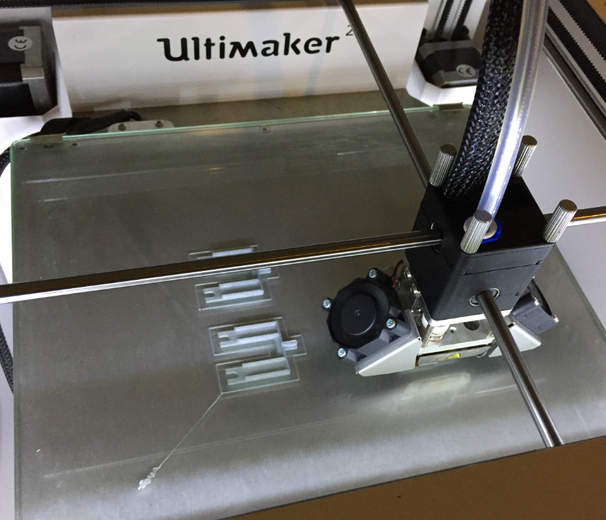
Thanks for an excellent site. I am considering building a PnP machine, what 3D printer you recommend.
MikeZ
LikeLiked by 1 person
Hi MikeZ,
I’m using the Ultimaker 2 for years and I’m very happy with it. But there are certainly other good printers out there: beside Ultimaker I would recommend to have a look at the Prusa ones too.
Good luck!
LikeLike
Congratulations, Eric, I want to share my videos about the pick & place machine.
You inspired me to create it, but now it helps a lot.
Since then, I have changed and learned a lot.
Visit my page, watch the video and share it with anyone who is interested.
We keep in touch and share experiences.
All the best to you, be healthy.
Thanks.
LikeLiked by 1 person
Great to hear that my work and the one of the OpenPnP community has inspired you!
LikeLike
Hi Eric
I found you very fantastic and detail description on the PNP machine you made , now four years back . I have a rebuild Isel CNC machine that is equipped with a jetting equipment for dispensing (I Have been able to dispense conductive drops down to less than 0.2 mm) and now I want to add a very basic PNP module for use with a single waver die 2.4×2.4 x0.3 mm. I have a resolution of 10 um for the stepmotors and also want to place component down to 0201 or even 0100 (0.4×0.2 mm) I have looked at you bom list and found the NEMA 11 Head motors for 5 mm screw. I need only one nozzle head Should you still recommend the same step motor with samsung CP40 nozzles , now four years later ?. I am ready to order from your bom list the proper part inclusive the USB camera
I do think it is a good idea to hear from you if your selection of components scope is still the best and valid .
I hope to hear from you soon . It should be very nice to be able to use use your suggested solution for my application
Best Regards
Lars.herrnsdorf
LikeLiked by 1 person
Hi Lars,
first: thank you!
As for 0201 or 0100: I’m using my machine mostly with 0603 components, and that works fine. I have placed 0402 too, but in reality this is just a little beyond the border the machine can do in a reliable way. I’m still happy with the CP40 nozzles, however it depends on the quality of the supplier. I have received some better and some worse nozzles, and I have not found a good way to know this in advance. So I have ordered from different suppliers and then sorted out things as needed.
As for the components I have used overall: this is still good to me, but of course there are challenges these days to get the Smoothieboard. As for the USB camera: there are better ones these days, but in my opinion they don’t get much more advantage.
I hope this helps,
Erich
LikeLike
Hi Erich, I designed PCB for the “SmoothieBoard” clone (based on schematics from http://smoothieware.org/) in size 100×100 mm. Nearly all the components are in SMD (1206) and couple of them are THT. The most difficult component to populate is LPC1769 processor. I can provide gerber files, if someone has interest to build this board himself / herself … just send me an email. It is already tested on my bench and it definitively works ;-).
LikeLike
Hi Josef,
that’s very good news, as original Smoothie board are really hard to get. I don’t need another board. I have currently two and they run fine for me.
LikeLike
Hi Erich,
finally I published it on my web pages … https://jopl.eu/openpnpdriver.php
In case of anybody interest, he / she can download supportive files for production.
Regards, Josef
LikeLike
Excellent, thanks for sharing! I would recommend to share it in the OpenPnP community too?
LikeLike
Hi Erich,
unfortunately I am not a member … Would you be so kind and could you share link to my pages there, please? Regards, Josef.
LikeLike
Simply sign up on https://groups.google.com/g/openpnp
LikeLike
And just one question … don’t you have got updated configuration files (from “.openpnp2” folder), please? When I try to use your files from download link, “Configuration Load Error” dialog appears … first one is about error during reading machine.xml file (Attribute ‘invert-vacuum-sense-logic’ does not have a match in class org.openpnp.machine.reference.ReferenceNozzle at line 6). Josef.
LikeLike
No, I don’t have an updated configuration. I still kept using that version of OpenPnP. I was trying to upgrade at one time to a newer version, but the configuration was not compatible any more, and it would have required me to configure the full machine again. To much work and risks at that time.
LikeLike
Understood, thx for reply. Josef.
LikeLike
Just finally starting my build, I ordered components already some years ago… I will start by building the 3D parts next from the stl files in 3D folder. Is there a list anywhere how many of each parts are needed?
LikeLike
There is no number of parts specified, as it depends on how much you want to use for your machine.
LikeLike
Hello. I started building pick&place a long time ago. Everything turned out very well thanks to your article. I designed my mechanism, and used your machine.xml to start, then adjusted it to my design. Everything works very well on all 3 pieces of equipment. And all this on OpenPNP v1.0. and now I wanted to add an industrial traffic light, and tried all methods to integrate it using actuators. I have already written a script that detects an error when recognizing a component on the lower camera. But these are just crutches. Question to you: could you help? I promise a monetary reward. Thank you for understanding. Please help.
LikeLike
it should be fairly easy to add and use external actuators. One way is to deal with custom G-Code on your machine (assuming you have control over the firmware on it).
LikeLike