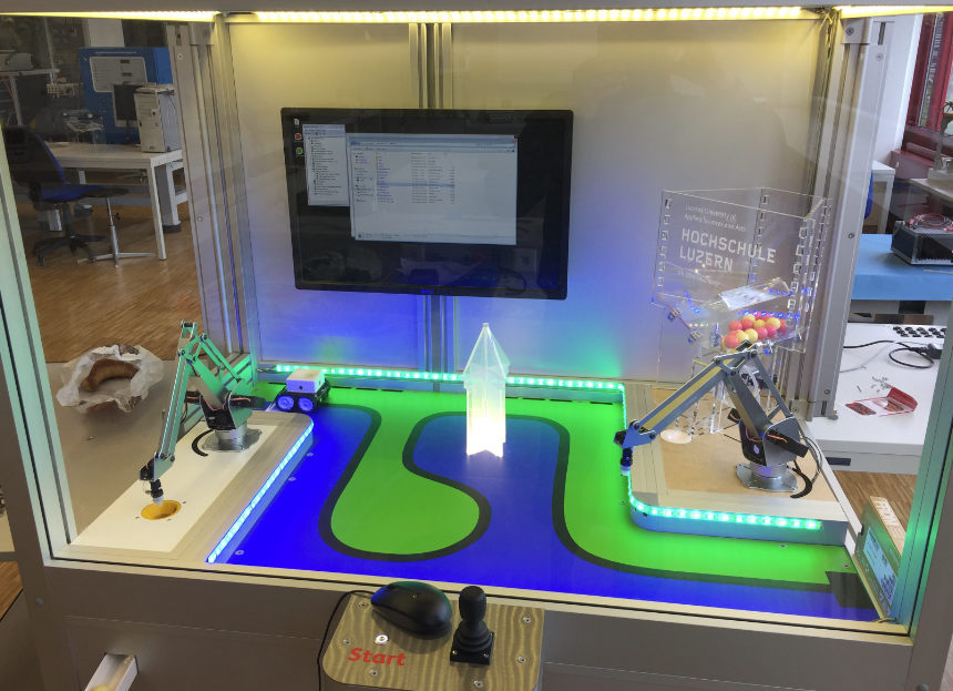
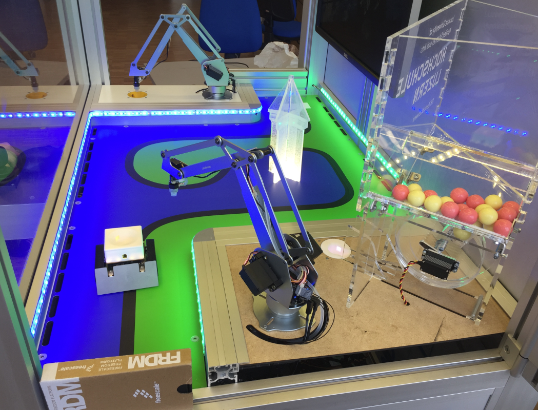
How to fascinate kids for technology? Show them that engineering is fun :-). At the Lucerne University of Applied Sciences and Arts we have created the ‘MINTomat’: a robotics system for STEM activities rewarding interaction with bubble gums:
MINTomat
Yes, pretty over engineered compared to a normal bubble gum automata, but that’s part of the fun :-).
MINT is the German language equivalent for STEM. The basic idea is a fun system which puts out bubble gums or mints with human interaction. The user has to use three robotics system to carry a bubble gum out of the system. The following video shows first tests with the system:
Mobile Robot
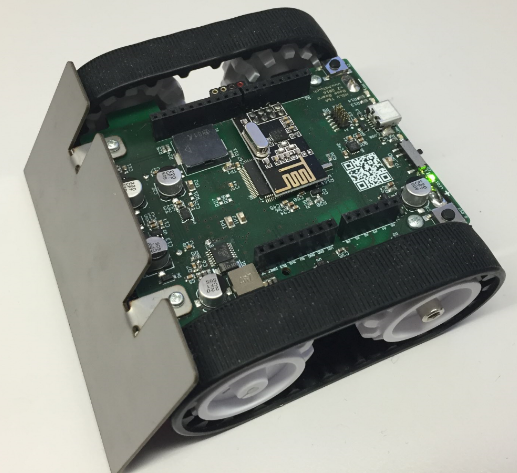
The base of the mobile robot is our version of the Zumo robot running with FreeRTOS on an NXP ARM Cortex-M4F. It uses the Nordic Semiconductor nRF24L01+ 2.4 GHz transceiver to communicate with the controller board:
INTRO Zumo Robot
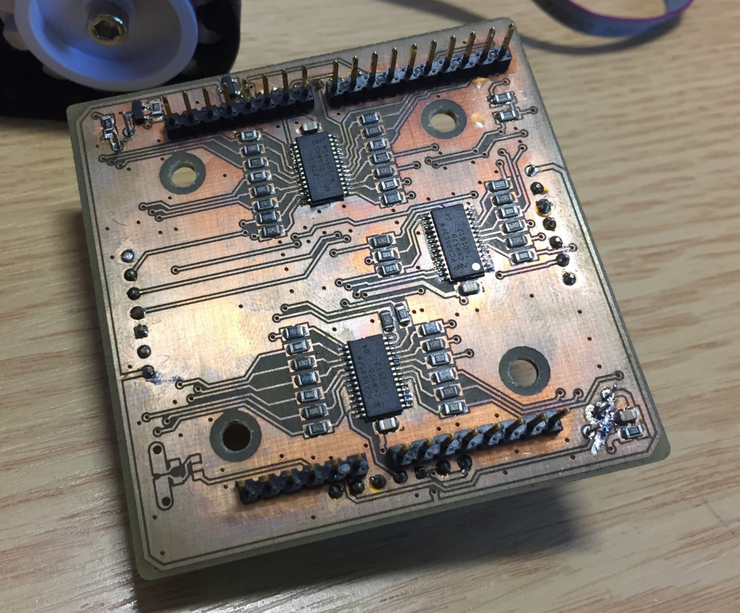
On top of the robot there is a special shield with 3 NXP PCA9685 16-channel 12-bit PWM LED controller. Below is the first prototype of the hardware:
First version of the shield
It had 13 RGB LEDs on top of it:
First version, top side
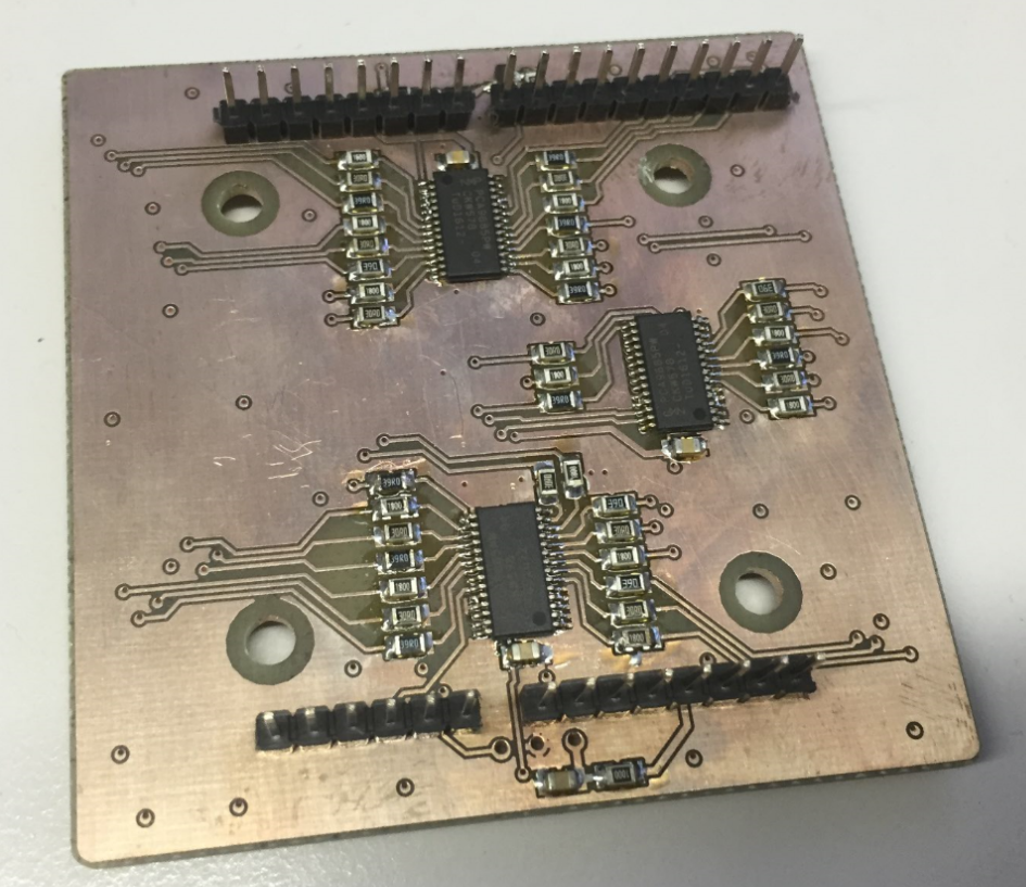
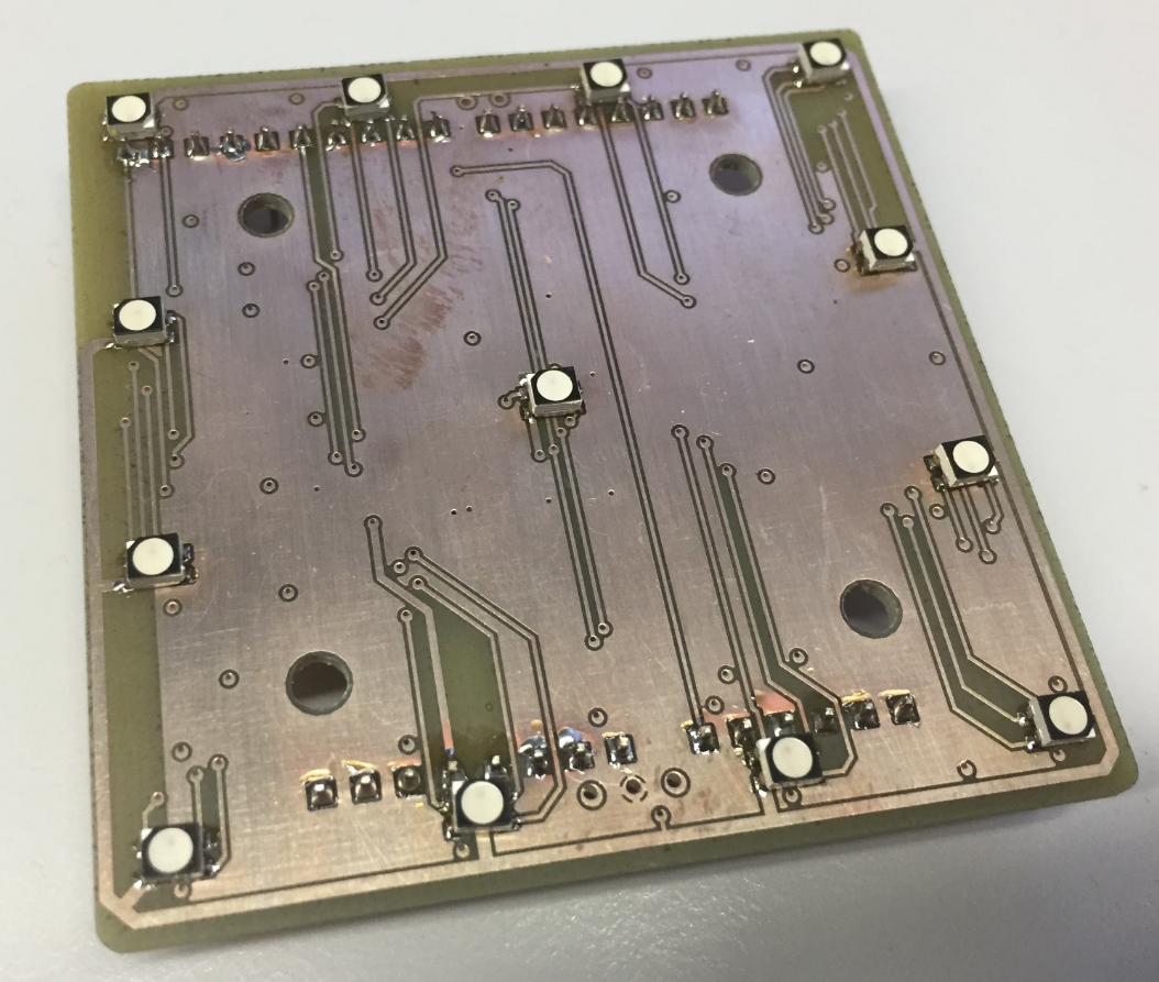
This is the second prototype, still three NXP PCA9685 on the bottom side:
MINTomat Robot Shield
On the top there are again 13 RGB LEDs, plus a 32 kHz IR transmitter/receiver and four ToF (Time of Flight) sensors on each side of the robot. The ToF sensors allow to measure distances up to 20 cm with a 1 mm resolution or up to 60 cm with 3 mm resolution:
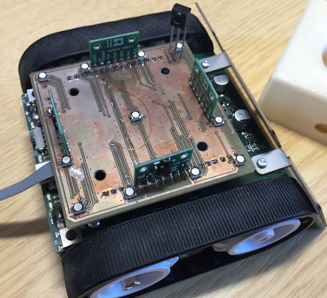
Top Side of the Shild with Sensorso
Sensors have been tested first on a bread board:
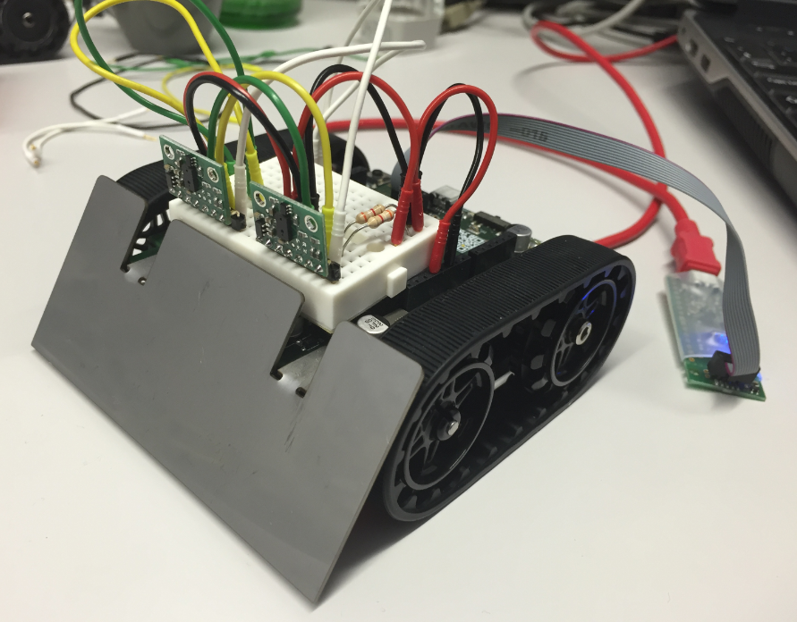
ToF Sensor Breadboarding
To avoid the robot running of the table ;-), it has been tested tested inside a cardbox (what I name ‘cardboxing’) 🙂 :
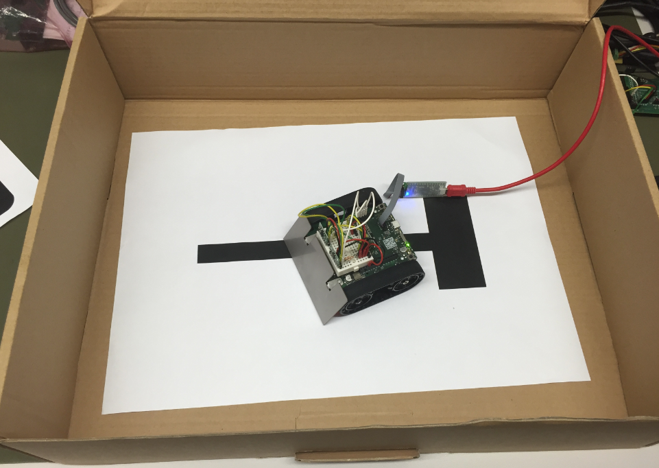
cardboxing with the robot
A 3D printed case is put on top of the shield to hold the bubble gum or any kind of capsules. The infrared transmitter/receiver detects if an object is inside the carrier, and the ToF sensors help the robot to detect obstacles or navigate inside the playing area. The LEDs glow inside the 3D printed material, creating a cool effect:
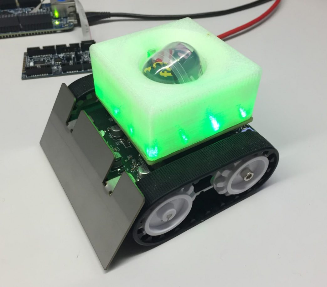
Robot LED Effect
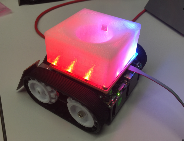
LED Effect with Red and Blue
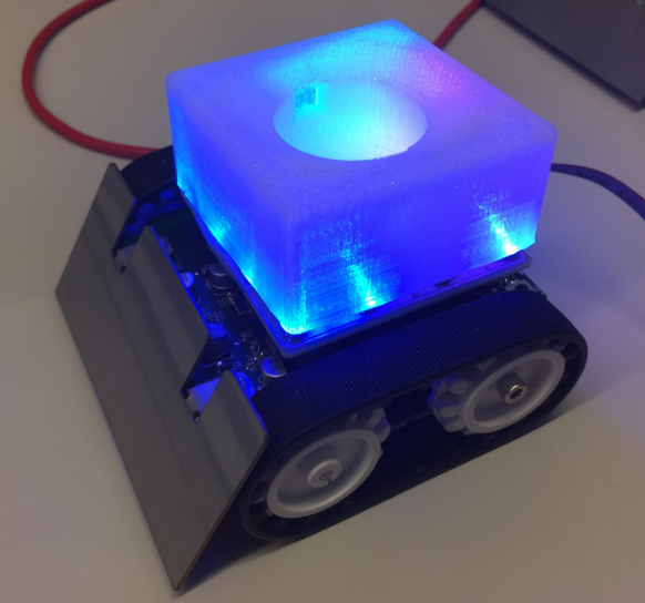
LED effect in blue
As always, there were several challenges with this project: time was extremely tight, with nearly no time for testing (sounds familiar, right?). Second, the I²C signals from the ToF sensors were not good because of wrong pull-up resistors on the board:
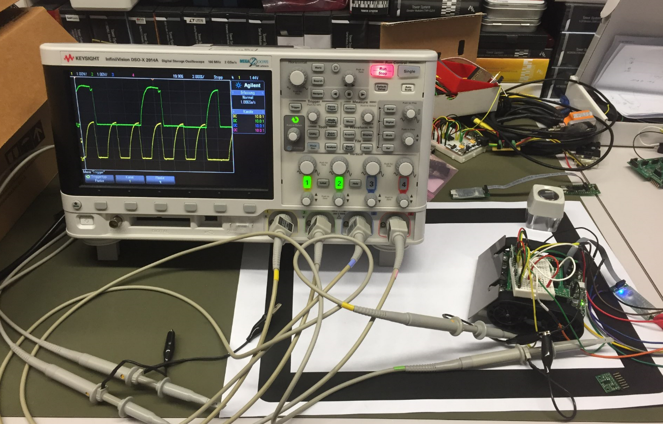
Testing I2C Signals
Other challenges were on the mechanical side. For example the laser-cut bubble gum dispenser required a lots of testing to work properly. A servo tester is used for manual testing the mechanics:
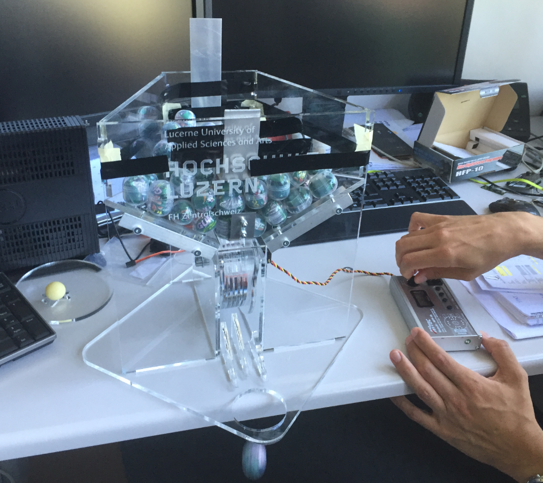
Bubble Gum Dispenser Tests
Below the automata box under construction:
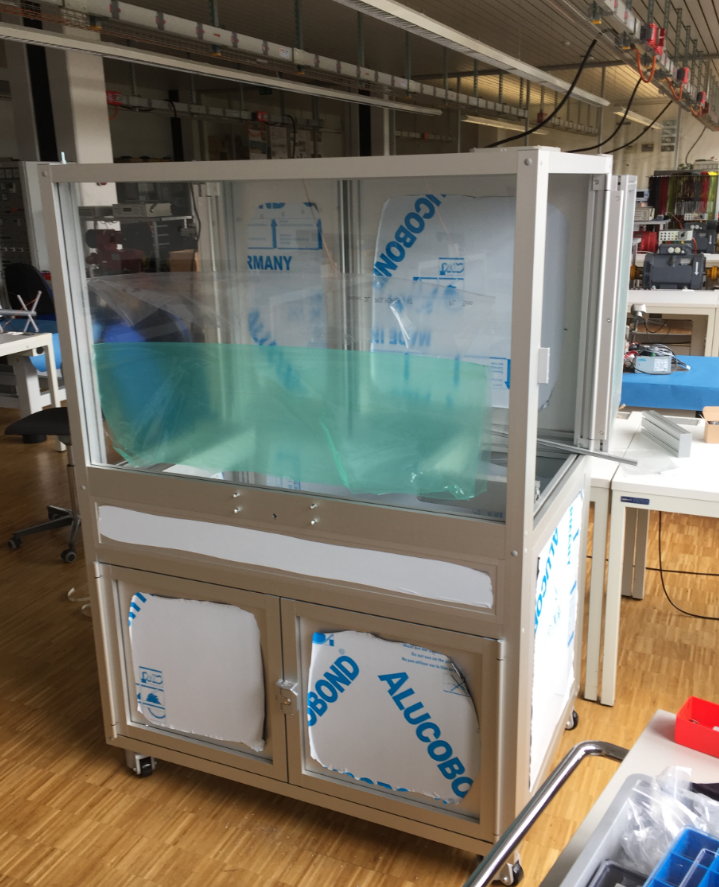
MINTomat box under construction
The controller board is using a tinyK20 with the nRF24L01+ transceiver.
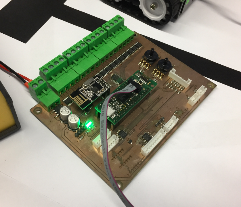
Mintomat TinyK20 Controller Board
The controller board is responsible for:
- Monitor the air pumps of the two robot arm with two pressure sensors.
- Communication with the mobile robot using 2.4 GHz nRF24L01+ transceiver.
- Communication with the display system over USB CDC.
- Read in joystick and push buttons plus sensor switches.
- Control the RGB LED stripes.
The controller board is mounted under the right robot arm system and the gum dispenser:
Mintomat under construction
Summary
The project had to be completed in a few days, with no real testing and a lot of temporary workarounds in place. The MINTomat is on a roadshow now and kids love it :-). However, because things had to be done in a rush, we already had to repair it. But that would be subject of another post….
Happy Minting 🙂
Links
- NXP PCA9685 16-channel 12-bit PWM LED controller: http://www.nxp.com/products/power-management/lighting-driver-and-controller-ics/i2c-led-display-control/16-channel-12-bit-pwm-fm-plus-ic-bus-led-controller:PCA9685
- STM VL6180X Time of Flight Sensor: http://www.st.com/content/st_com/en/products/imaging-and-photonics-solutions/proximity-sensors/vl6180x.html

Pingback: Failure with Solder Points and Mechanical Pressure | MCU on Eclipse
Pingback: Mintomat: An Overcomplicated Gumball Machine | Hackaday
Pingback: Tutorial: STMicroelectronics VL6180X Time-of-Flight LIDAR Sensor | MCU on Eclipse