The first enclosure for the INTRO robot remote controller board (see “INTRO Robot Remote – First Production PCB“) is ready, and it is looking good:

Enclosure for the Remote Controller Board
The main purpose of this board is to communicate with the INTRO robot using the Nordic Semiconductor nRF24L01+ 2.4 GHz transceiver:

Remote Controller with Robot
The above picture shows the first board and enclosure: for the next enclosures the mounting holes will be on the bottom side (this was a mistake with the first enclosure).
The tinyK20 board can be debugged with JTAG/SWD debuggers e.g. Eclipse/Kinetis Design Studio:

Open Enclosure
The On-Off switch is now mounted on the bottom side of the board to keep the area free for the SemTech LoRa wireless module.

Side with USB connector and on-off switch
The navigation switch, tinyK20, LCD and battery can be removed from the board if needed. The tinyK20 USB port is used for USB (e.g. CDC or bootloader) and for power and charging the battery.
We faced possible issues with the battery charging circuit too close to the nRF24L01+ nRF24L01+ 2.4 GHz Wireless Connectivity with the tinyK20 Boardtransceiver. We solved it by adding more decoupling capacities plus mounting the 2.4 GHz module on the other side of the PCB:

nRF24L01+ Transceiver
In a next revision of the board, I plan to move the module to the other side of the PCB, far away from the battery charging circuit. After the fact, mistakes are always so obvious :-(.
The software for the LCD provides a hierarchical menu structure. It now has a vertical scroll bar on the right side:

LCD Menu Scroll Bar
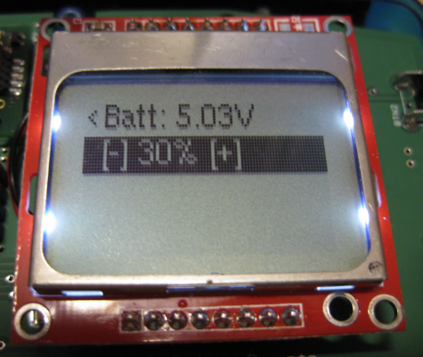
The software can automatically query and set values using the 2.4 GHz channel, for example query the current battery voltage of the robot:

LCD Remote Values
Clicking on a menu item allows to edit the value and update the value on the robot, using the left/right/up/down key. Entering on the value shows the current value which then can be edited:
Editing Values
Then I can use the left/down button to decrease the value, and the up/right button to increase it:

Editing the value
Pressing enter again stores the value and sends it to the robot:

New PID Value
Summary
The 20 boards for course are in production now. As always with this kind of projects, the first version is never perfect. But the current design is very usable, and having the ability with the LCD to inspect and change settings of the robot is a great addition to the course material and learning content.
Happy Enclosing 🙂

Erich, nice job, compact and simple to use. There is always the “why did I put that there” moment on first proto.
LikeLike
Pingback: 2017 Spring Semester Sumo Challenge | MCU on Eclipse