
The ARM Cortex-M microcontroller are very popular. And it has a very flexible and powerful nested vectored interrupt controller (NVIC) on it. But for many, including myself, the Cortex-M interrupt system can be leading to many bugs and lots of frustration :-(.

ARM Cortex-M7: NXP KV58
Understanding the NVIC and the ARM Cortex-M interrupt system is essential for every embedded application, but even for if using an realtime operating system: if you mess up with interrupts, very bad things will happen….
💡 I have found the article from Miro Samek very helpful for understanding the ARM Cortex interrupts, and concepts of his article in https://embeddedgurus.com/state-space/2014/02/cutting-through-the-confusion-with-arm-cortex-m-interrupt-priorities/ have been used in this article too, so be sure to check out his work too (the links to his articles are in the Links section too).
Introduction
FreeRTOS is probably the most popular operating system for microcontroller. It supports many different architectures, including the ARM Cortex-M architectures.
I’m covering the topic of FreeRTOS and interrupts in my university lecture material. I have seen so many cases of incorrect interrupt usage within the RTOS that I think it deserves a dedicated article. Amazingly, I see many times over that even if the interrupts are configured in a clearly wrong way, surprisingly the application ‘seems’ to work, at least most of the time. Well, I think everyone agrees that ‘most of the time’ is not good enough. Because problems with interrupts are typically hard to track down, they are not easy to fix.
In this article I’m discussing ARM Cortex-M0/M0+ (ARMv6-M), M3(ARMv7-M) and M4/M7 (ARMv7E-M). In Part 1 (this article) I give an overview on the ARM Cortex-M interrupt system. In Part 2 (which will follow in the not-so-far-future, I explain how it is used by FreeRTOS and how it affects the application.
Interrupt Vectors
The ARM Cortex-M is using a NVIC (Nested Vectored Interrupt Controller). The ‘vectored’ means that it uses a vector table, shown for M0/M0+ and M4/M4 below:

Cortex-M Vector Table (Source of images: ARM)
The table is ‘vectored’, because the 32bit entries in it (e.g. the Hard fault vector at address 0x000C’0000) point to the corresponding interrupt service routine: for example the entry at address 0x08 ‘vectors’ to the NMI interrupt handler or function.
The exception numbers 1 to 15 are defined by ARM, that is they are part of the core. The exception above 15 are ‘vendor specific’, this means that they are implemented by vendors like NXP, TI, STM and many others.
Or in other words: the negative IRQ numbers (from -1 (SysTick) to -14 (NMI) plus reset) are defined by the ARM core, everything else ‘above’ with IRQ number >=0 are vendor specific and typically for devices like UART/I²C/USB/etc..
💡 Note in above image the numbering or Exception Numbers and IRQ numbers: they easily get mixed up and causes confusion.
Interrupts Priorities
The ARM Cortex-M core is using a rather confusing interrupt priority numbering: numerically low values are used to specify logically high interrupt priorities. Or in other words: the lower the number, the higher the urgency.
💡 I try to use the word ‘urgency’ to indicate how ‘important’ an interrupt is, not to confuse with the (ARM hardware) interrupt priority (level). In a nested interrupt system such as on ARM Cortex-M, a ‘more urgent’ interrupt can interrupt a ‘less urgent’ interrupt.
This means that interrupt priority 0 is the ‘most urgent one’.
At reset, all interrupt priorities have a priority of zero assigned. I can assign a priority to each of them. Except that Reset, NMI and HardFault have a fixed (negative) priority and cannot be disabled. The following table shows all the exceptions/interrupts, and for which ARM Cortex-M core they exist:

Exception and Priorities
Priority Bits
The priority of the exception/interrupt is assigned with a 8bit priority register, and the number of bits implemented is up to the vendor implementation. ARM specifies a minimum of 2 bits for the M0/M0+ and 3 bits for M3/M4/M7.
If using CMSIS compliant libraries, the number of implemented bits can be checked with
__NVIC_PRIO_BITSThe example below is for a NXP Cortex-M7 (see “First steps: ARM Cortex-M7 and FreeRTOS on NXP TWR-KV58F220M“) which has 4 bits implemented
#define __NVIC_PRIO_BITS 4 /**< Number of priority bits implemented in the NVIC */
Shifted Priority Bits
The implemented priority bits are ‘left-aligned’: this keeps priority values compatible between different implementations:

3 Interrupt Bits Implemented
For three implemented bits, it means I can have 2^3 (8) priority levels, with the following (shifted) values:
- Hexadecimal: 0x00, 0x20, 0x40, 0x60, 0x80, 0xA0, 0xC0, 0xE0
- Decimal: 0, 32, 64, 96, 128, 160, 192, 224
💡 There is much confusion about ‘shifted’ and ‘not shifted’ priority values. Carefully check the API of the CMSIS API function if they expects shifted or not shifted values! Using the CMSIS API is the preferred way to deal with the ARM core and its core registers.
If the device has implemented only 4 priority bits (e.g. the Kinetis K series of NXP), then we have 2^4 (16) priority levels, with the following shifted values:
- Hexadecimal: 0x00, 0x10, 0x20, 0x30, 0x40, 0x50, 0x60, 0x70, 0x80, 0x90 0xA0, 0xB0 0xC0, 0xD0, 0xE0, 0xF0
- Decimal: 0, 16, 32, 48, 64, 80, 96, 112, 128, 144, 160, 176, 192, 208, 224, 240
If the device has implemented only 2 priority bits (e.g. the Kinetis L series of NXP), then we have 2^2 (4) priority levels, with the following shifted values:
- Hexadecimal: 0x00, 0x40, 0x80, 0xC0
- Decimal: 0, 64, 128, 192
NVIC Interrupt Configuration
The NVIC offers several registers to configure the interrupts. On the M0/M0+ there are the following
- NVIC_ISER (Interrupt Set Enable Register): enable interrupt bit, one bit for each device specific interrupt
- NVIC_ICER (Interrupt Clear Enable Register): disable interrupt bit, one bit for each device specific interrupt
- NVIC_ISPR (Interrupt Set Pending Register): mark interrupt as pending bit, one bit for each device specific interrupt
- NVIC_ICPR (Interrupt Clear Pending Register): clear pending flag bit, one bit for each device specific interrupt
- NVIC_IPRx (Interrupt Priority Register): interrupt priority (8bit for each interrupt, 4 interrupts in a 32bit register)

NVIC Interrupt Registers on Cortex-M0+
The above registers are 32bit registers, with one bit for each interrupt. For example the NXP KL25Z has a total of 32 interrupts (IRQ 0-31) (core + vendor specific), so 32bits for each bit of the above registers are enough. For the 32 interrupts priorities 32*8bit == 8 32bit priority registers (NVIC_PRI0…PRI7) are used.
Below screenshot shows the individual bits in NVIC_ISER:

NVIC Interrupt Bits
The Cortex-M3/4/7 has one register more in addition to the one above:
- NVIC_IABR (Interrupt Active Bit Register): set if an interrupt is running, one bit for each interrupt
Here again there is a single bit for each interrupt. For example the NXP K64 (ARM Cortex-M4F) has 15+86 vendor specific interrupts (exceptions 0x10-0x65) with a total of 101 interrupts, so it needs 101/32=4 32bit registers to hold all the bits for ISER, ICER, ISPR and ICPR) and 101 8bit registers for the 8bit priorities (IP).
Assigning Interrupt Priority
To set the interrupt priority, the following CMSIS function is used:
void NVIC_SetPriority(IRQn_Type IRQn, uint32_t priority);
IRQn is the interrupt (IRQ) number (0 for the first vendor specific exception, -1 for SysTick, -2 for PendSV etc.). ‘priority’ is the not-shifted (!!!!) interrupt priority, e.g. 0-7 for a system with 3 bits.
💡 This mix-up with shifted and non-shifted values is very much confusing and a common source of wrong code, even books have it wrong 😦
For example
NVIC_SetPriority(SysTick_IRQn, (1UL<<__NVIC_PRIO_BITS)-1UL); /* set Priority for Systick Interrupt to lowest interrupt */
sets the SysTick to the lowest interrupt level given the available levels (SysTick_IRQn is a macro having the value -1).
Notice that NVIC_SetPriority accepts IRQ numbers from -15….0….n where values greater-equal zero are device/vendor specific interrupts. And that the priority is the non-shifted (!!!!) value:
/**
  \brief   Set Interrupt Priority
  \details Sets the priority of an interrupt.
  \note    The priority cannot be set for every core interrupt.
  \param [in]      IRQn  Interrupt number.
  \param [in]  priority  Priority to set.
 */
static void NVIC_SetPriority(IRQn_Type IRQn, uint32_t priority)
{
  if ((int32_t)(IRQn) < 0)
  {
    SCB->SHP[(((uint32_t)(int32_t)IRQn) & 0xFUL)-4UL] = (uint8_t)((priority << (8U - __NVIC_PRIO_BITS)) & (uint32_t)0xFFUL);
  }
  else
  {
    NVIC->IP[((uint32_t)(int32_t)IRQn)]               = (uint8_t)((priority << (8U - __NVIC_PRIO_BITS)) & (uint32_t)0xFFUL);
  }
}
Sub-Priorities
On the M3/M4/M7 it is possible to have sub-priorities for the interrupts, and the number of subpriority bits is configured by the PRIGROUP register. The PRIGROUP can be changed at runtime:

PRIGROUP Register
In the above example, the PRIGROUP is set to zero (no sub priorities). The value of PRIGROUP sets the bit position of the sub priority bits: For example if PRIGROUP has a value of 5 (bit position 5) and number of priority bits are 3, then there are 2 main/preemption priorities and one sub priority:
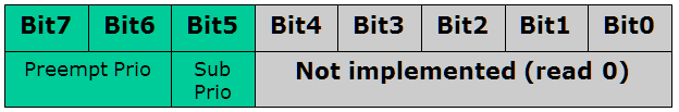
System with 3 Priority bits, 2 are preemption priority and one sub priority bit
With sub priority there are now two different priorities for an interrupt: <Preempt Prio>.<Sub Prio> to have a notation for it.:
- The Preempt Priority defines if an interrupt can nest/interrupt an already running interrupt. Remember that a lower preemption priority number means higher urgency. For example an interrupt with 2.1 can nest/interrupt a running interrupt 3.0.
- The Subpriority is used when multiple interrupts with the same Preemption Priority are pending, then the one with the lower sub-priority (higher urgency) will be executed first. For example if 3.1 and 3.0 are pending, then 3.0 will be executed first. It means as well that the interrupt 3.0 will not be able to interrupt/nest another 3.1 interrupt.
To change the number of sub-priority bits, the
void NVIC_SetPriorityGrouping(uint32_t PriorityGroup)
is used. While sub-priorities provide great flexibility, many systems do not use it because it adds more complexity. Even worse, some libraries are setting non-standard sub-priority levels, in that case
NVIC_SetPriorityGrouping(0);
disables sub-priorities.
Interrupts and Devices
Multiple interrupt enabled devices (e.g. UART, USB, etc) can have the same priority assigned, so they don’t need to be uniquely assigned on Cortex-M.
Out of reset, interrupts are disabled and the interrupt priorities for all are set to zero.
To enable interrupts for a given device (e.g. I²C interrupt), the following steps are needed:
- Optional: set the priority level of the required interrupt in the NVIC
- Enable the interrupt inside the device (usually a device specific bit, e.g. bit in the I²C peripheral register)
- Enable the interrupt in the NVIC
For an example of the I²C interrupt, this could look like this:
#define I2C1_IRQn  24 /* device specific interrupt for I2C */
#define I2C1_BASE  (0x40067000u)  /* address of peripheral */
#define I2C1       ((I2C_Type *)I2C1_BASE) /** Peripheral I2C0 base pointer */

NVIC_SetPriority(I2C1_IRQn, 1); /* set I2C interrupt level (note: 1 is *not* shifted! */
I2C1->C1 |= I2C_C1_IICIE_MASK; /* enable device specific interrupt flag */
NVIC_EnableIRQ(I2C1_IRQn); /* Enable NVIC interrupt */
To turn off the device interrupts, simply disable it with a NVIC call:
NVIC_DisableIRQ(I2C1_IRQn); /* Disable NVIC interrupt */
The fact that there are both the NVIC and device specific interrupt enable/disable bits might be confusing. My recommendation is to disable first the device internal interrupt bit before doing any device register configuration. This ensures that the device is not creating any interrupts to the NVIC. To turn on/off the (device specific) interrupts, use the NVIC interrupt enable/disable bits (NVIC_ISER and NVIC_ICER).
Masking Interrupts
The NVIC not only allows to set interrupt priorities, it allows to enable/disable each interrupt one by one. But for critical sections or atomic accesses it is necessary to turn off all interrupts.
PRIMASK
All the cores discussed here have the ‘I’ (interrupt) bit in the PRIMASK (Primary Mask) register:

PRIMASK Register
Setting that bit masks (disables) the interrupts. There is a simple assembly instruction doing this:
__asm volatile("cpsid i"); /* disable interrupts */
The other way around, clearing the bit enables (globally) all interrupts:
__asm volatile("cpsie i"); /* enable interrupts */
If using CMSIS libraries, then the following functions are available:
void __enable_irq(void);
void __disable_irq(void);
Disabling all interrupts in a system increases interrupt latency time, so this should be as short as possible.
BASEPRI
The M3/M4/M7 cores (not the M0/M0+!) have another great feature: the BASEPRI (Base Priority Mask) register:
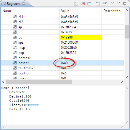
BASEPRI Register
The BASEPRI register is a mask register and masks all interrupt priorities levels which are ‘numerically equal or higher (lower urgency!) than the BASEPRI value’.
💡 As for the interrupt priorities, this register uses the shifted bits!
From the ARM Infocenter:
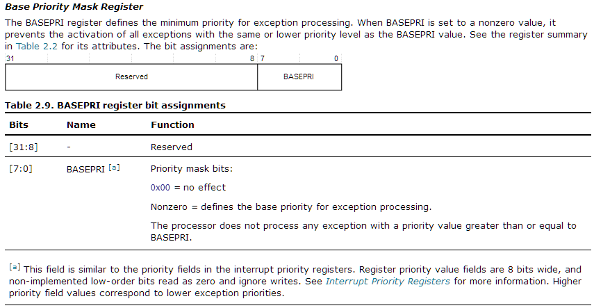
ARM BASEPRI
💡 Notice the usage of ‘priority value’ and ‘priority level’ in above description!
So it means: if non-zero, it allows interrupts with priority numerical values smaller than BASEPRI value, and blocks interrupts with numerical values equal or higher than BASEPRI value.
Examples (assuming (hypothetical) 8 priority bits implemented):
- BASEPRI set to a value of 3: disables interrupts with values 3, 4, 5, 6, …, 255. Allows any interrupts with numerical value of 0, 1 and 2.
Higher numerical values mean lower priority (less urgency!). So setting BASEPRI to 3 will disable all interrupts with a higher prio value (less urgent) than 3, so that 0, 1, 2 will stay enabled, but 3,4,5 6, … are disabled.
💡 Because BASEPRI is a mask register: setting it to zero means interrupts are not masked and therefore enabled. It means that it cannot mask/disable interrupts with priority zero! Use the PRIMASK to disable interrupts with priority zero.
Here is an example for an implementation with 2 priority bits with no subpriorities:
- Has 2^2 (4) priority values: 0x00, 0x40, 0x80 and 0xC0
- Setting BASEPRI to 0x80 will mask/disable 0x80 and 0xC0. 0x00 and 0x40 are still enabled.
CMSIS offers the following function to set the BASEPRI register:
void __set_BASEPRI_MAX(uint32_t value);
Let’s have a look at the CMSIS implementation for GNU:
/**
  \brief   Set Base Priority with condition
  \details Assigns the given value to the Base Priority register only if BASEPRI masking is disabled,
           or the new value increases the BASEPRI priority level.
  \param [in]    basePri  Base Priority value to set
 */
__attribute__( ( always_inline ) ) __STATIC_INLINE void __set_BASEPRI_MAX(uint32_t value)
{
  __ASM volatile ("MSR basepri_max, %0" : : "r" (value) : "memory");
}
So it does *not* shift the priority inside the function, so I have to do that outside in the function call like this:
__set_BASEPRI_MAX(priority<<(8-__NVIC_PRIO_BITS));
Using the BASEPRI it is possible to mask the interrupts up to a certain level. This is critical for a good interrupt partitioning of the system, and FreeRTOS takes advantage of the BASEPRI setting. More about this in Part 2 of this article.
Summary
The ARM NVIC and interrupt system is complex, in many areas with the CMSIS API not logical or counter-intuitive, and uses an inverted priority vs. urgency scheme. The shifted vs. non-shifted priority values can cause subtle bugs and issues I have faced. Between the ARMv6-M, ARMv7-M and ARMv7E-M, the interrupt system is similar and somewhat compatible, but still different. Vendor libraries might not be consistent dealing with the interrupts or setting some grouping, so carefully check how they are implemented.
Understanding the interrupt system and how to use it is an essential part for embedded systems. The interrupt system and controller has an impact on how drivers and middleware are using the interrupts.
The RTOS is such a case where understanding and mastering the interrupts is critical to ensure proper operation and minimize interrupt latency. In Part 2 of this article I will describe how the ARM Cortex-M interrupts are used by FreeRTOS, and what it means for the application.
So far, I hope this part is already useful for you.
Happy Cortexing 🙂
Links
- ARM Cortex-M, Interrupts and FreeRTOS: Part 1
- ARM Cortex-M, Interrupts and FreeRTOS: Part 2
- ARM Cortex-M, Interrupts and FreeRTOS: Part 3
- FreeRTOS operating system: http://www.freertos.org/
- Running FreeRTOS on ARM Cortex-M core: http://www.freertos.org/RTOS-Cortex-M3-M4.html
- Wikipedia on ARM Cortex-M: https://en.wikipedia.org/wiki/ARM_Cortex-M
- The Definitive Guide to the ARM Cortex-M0 and Cortex-M0+ Processors; 2nd Edition; Joseph Yiu; Newnes; 784 pages; 2015; ISBN 978-0128032770
- The Definitive Guide to the ARM Cortex-M3 and Cortex-M4 Processors; 3rd Edition; Joseph Yiu; Newnes; 600 pages; 2013; ISBN 978-0124080829
- Interrupt Latency on Cortex-M: https://community.arm.com/docs/DOC-2607
- Miro Samek: Cutting through the Confusion: http://embeddedgurus.com/state-space/2014/02/cutting-through-the-confusion-with-arm-cortex-m-interrupt-priorities/
- Miro Samek: https://community.arm.com/iot/embedded/b/embedded-blog/posts/cutting-through-the-confusion-with-arm-cortex-m-interrupt-priorities
- ARM Cortex Microcontroller Software Interface Standard (CMSIS): http://www.arm.com/products/processors/cortex-m/cortex-microcontroller-software-interface-standard.php

Please be aware that the value passed to __set_BASEPRI() and __set_BASEPRI_MAX() is not automatically shifted, you need to explicitly use something like __set_BASEPRI(priority << (8 – __NVIC_PRIO_BITS)); similarly, actual values in the BASEPRI register rather look like 0x10, than 0x1, as you depict them.
Liviu
LikeLiked by 1 person
Hi Liviu,
yes, indeed I used the wrong screenshot, and I realize that the description was not clear (to my point: it is confusing 😉 ). I have updated the image and description now.
Multumesc!
LikeLiked by 1 person
It seems correct now, but the example with 8 priority bits is not realistic, I did not encountered such a chip. I guess less confusing would be a real world example, with 3-4 priority bits.
LikeLike
Happy Cortexing 🙂 Very informative article. I didn’t know about sub-priorities in ARMv7m. I’m waiting for part 2!
LikeLike
Great description! As Eric says, the numbering is quite confusing. So confusing that the author mixed one thing up: 🙂
The BASEPRI register is a mask register and mask all interrupt priorities which are ‘numerically equal or lower than the BASEPRI value’.
Examples:
BASEPRI set to 3: disables interrupts with priority 3, 2 and 1
BASEPRI set to 5: disables interrupts with priority 5, 4, 3, 2 and 1
Higher numerical values mean lower priority (less urgency!). So setting BASEPRI to 3 will disable
all interrupts with a higher prio value (less urgent) than 3, so that 0, 1, 2 will stay enabled, but 4,5 6, …
are disabled.
LikeLike
Hi Rolf,
great catch! Actually that’s one if the exams questions (hint, hint!), and you are right: I have been confused again and mixed up things (I should have known it better!).
Thanks for catching this, I have fixed it now. I hope that’s the only one :-).
Erich
LikeLike
> I hope that’s the only one
no, it isn’t 😦
as I said, for cores that use 4 bits for the priority, you need to set BASEPRI to values like 0x10, 0x20, etc.
LikeLike
Hi Liviu,
yes, I have updated the screenshot and description (hopefully correctly now). 🙂
LikeLike
To exemplify my statement, please check the critical_section::enter() function in https://github.com/micro-os-plus/micro-os-plus-iii/blob/xpack/include/cmsis-plus/rtos/port/os-inlines.h (about line 208).
These are the µOS++ IIIe / CMSIS++ definitions for the Cortex-M port.
LikeLike
Did you reverse 3.0 and 3.1 in the second sentence here?
For example if 3.1 and 3.0 are pending, then 3.0 will be executed first. It means as well that the interrupt 3.0 will not be able to interrupt/nest another 3.1 interrupt.
LikeLike
Hi Denis,
0 has higher urgency than 1, so 3.0 will be choosen first. An interrupt with the same main urgency, but higher sub urgency should not interrupt an alreday running interrupt as otherwise main/sub urgency would not make any difference to main urgency only.
I see if I can come up with another post on that subject.
Erich
LikeLike
Hi Denis,
I hope the examples in https://mcuoneclipse.com/2016/08/20/arm-cortex-m-interrupts-and-freertos-part-2/ can help?
LikeLike
Pingback: ARM Cortex-M, Interrupts and FreeRTOS: Part 2 | MCU on Eclipse
Pingback: ARM Cortex-M Interrupts and FreeRTOS: Part 3 | MCU on Eclipse
Pingback: Tutorial: RFID Tags with the NXP NFC Controller PN7120 and Eclipse | MCU on Eclipse
Pingback: Is Developing for ARM more difficult than for other Architectures? | MCU on Eclipse
“To turn of the device interrupts” – I think it’s supposed to be “off”, not “of”. It’s not a major issue by any means, but slightly confusing for the first read.
Thanks for the awesome article!
LikeLike
Thanks, fixed now!
LikeLike
Dear Erich,
First of all great article! Very helpful when studying the NVIC and ARM.
I believe you did mix up a comment in your code example:
NVIC_DisableIRQ(I2C1_IRQn); /* Enable NVIC interrupt */
Joris
LikeLike
Hi Joris,
thanks, and many thanks for spotting that copy-paste error I made :-(. I have it fixed now.
Best regards,
Erich
LikeLike
Hello Erich,
First of all thank you very much for this lovely website it has been an invaluable resource.
I don’t understand how you get the numbers for the priority registers needed for the Cortex-M4F
You say that there are 82 vendor specific exceptions where each needs 1 bit per exception.
This brings us to 82 and we would need 3 32-bit registers.
If we include the 16 ARM exceptions then this brings the total to 98 and we would indeed need 4 32-bit registers.
Now after that if there is 8 bits for priority in the first case it would be 82*8=656 bits which would need 20.5->21 registers. What am I missing?
LikeLike
Indeed, a copy paste error, and I got fooled by (I guess mistake) in the ARM CMSIS-SVD files. It should read
For example the NXP K64/K22 (ARM Cortex-M4F) has 15+86 vendor specific interrupts (exceptions 0x10-0x65) with a total of 101 interrupts, so it needs 101/32=4 32bit registers to hold all the bits for ISER, ICER, ISPR and ICPR) and 101 8bit registers for the 8bit priorities (IP).
Thanks for spotting this!
Erich
LikeLike
I think you have a typo in this section
“Assigning Interrupt Priority
To set the interrupt priority, the following CMSIS function is used:
void NVIC_SetPriority(IRQn_Type IRQn, uint32_t priority);
IRQn is the exception number (0 for the first vendor specific exception, -1 for SysTick, -2 for PendSV etc.). ‘priority’ is the not-shifted (!!!!) interrupt priority, e.g. 0-7 for a system with 3 bits.”
You say that the IRQn is the *exception* number….don’t you mean *IRQ* number? You go to lengths earlier to explain confusion between the 2 numbering systems….
“Or in other words: the negative IRQ numbers (from -1 (SysTick) to -14 (NMI) plus reset) are defined by the ARM core, everything else ‘above’ with IRQ number >=0 are vendor specific and typically for devices like UART/I²C/USB/etc..
💡 Note in above image the numbering or Exception Numbers and IRQ numbers: they easily get mixed up and causes confusion.”
However, what you describe in your description for the first parameter for SetPriority can only be an IRQ number, as you exemplify it as “-1 for systick” etc. and indeed the code snippet of it’s implemented, which you subsequently paste, has an is negative test in it’s first if statement.
Matt
LikeLike
Hi Matt,
indeed, it should be *interrupt* (IRQ) number, many thanks for catching this! I have fixed this now. It seems that I might add to the confusion myself here too 😉
LikeLike
Pingback: FreeRTOS: how to End and Restart the Scheduler | MCU on Eclipse
Hello Erich, thanks for this very valuable article that I’ve read already more than 10 times.
There’s one thing that I find unclear both in the CMSIS documentation and in your article, it’s about the NVIC ISER registers (and other interrupt registers) and which interrupts are managed through those registers. Your article states that :
“NVIC_ISER (Interrupt Set Enable Register): enable interrupt bit, __one bit for each interrupt__”
But “each interrupt” is unclear since there are device-specific interrupts and core interrupts. Here I think that ISER only covers device-specific interrupts.
From my understanding and reading of the NVIC functions, I think that NVIC ISER0 bit 0 concerns the first device-specific interrupt (which is 0). But as this is often unclear for me and some of my colleagues, perhaps it would be useful to indicate this here as well.
Note that when we interact with the CMSIS APIs we don’t really need to care. But in a middle of a debug session when looking into the registers, it becomes necessary.
Thanks for the great articles anyway 🙂 Although I liked my studies in a Western-Switzerland HES, I wish I had you as a teacher!
LikeLike
Hi Tim,
thanks for reading my articles :-).
You are right: the NVIC_ISER (and its twins) are for the device specific interrupts only. It is one of the ‘ARM confusing things’ causing so much troubles. The system IRQs are using negative numbers and the device specific ones start with zero as you have noticed, e.g. from a K22FX (ARM Cortex-M4):
typedef enum IRQn {

  /* Auxiliary constants */

  NotAvail_IRQn                = -128,             /**< Not available device specific interrupt */
/* Core interrupts */
NonMaskableInt_IRQn = -14, /**< Non Maskable Interrupt */
HardFault_IRQn = -13, /**< Cortex-M4 SV Hard Fault Interrupt */
MemoryManagement_IRQn = -12, /**< Cortex-M4 Memory Management Interrupt */
BusFault_IRQn = -11, /**< Cortex-M4 Bus Fault Interrupt */
UsageFault_IRQn = -10, /**< Cortex-M4 Usage Fault Interrupt */
SVCall_IRQn = -5, /**< Cortex-M4 SV Call Interrupt */
DebugMonitor_IRQn = -4, /**< Cortex-M4 Debug Monitor Interrupt */
PendSV_IRQn = -2, /**< Cortex-M4 Pend SV Interrupt */
SysTick_IRQn = -1, /**< Cortex-M4 System Tick Interrupt */
/* Device specific interrupts */
DMA0_IRQn = 0, /**< DMA Channel 0 Transfer Complete */
DMA1_IRQn = 1, /**< DMA Channel 1 Transfer Complete */
DMA2_IRQn = 2, /**< DMA Channel 2 Transfer Complete */
DMA3_IRQn = 3, /**< DMA Channel 3 Transfer Complete */
...
The CMSIS NVIC_EnableIRQ() only accepts positive IRQ numbers:
__STATIC_INLINE void __NVIC_EnableIRQ(IRQn_Type IRQn)

{

  if ((int32_t)(IRQn) >= 0)

  {

    NVIC->ISER[(((uint32_t)(int32_t)IRQn) >> 5UL)] = (uint32_t)(1UL << (((uint32_t)(int32_t)IRQn) & 0x1FUL));

  }

}
The system IRQs (e.g. SysTick) have dedicated register bits to turn them on/off.
I make a update in the article to make this clear, thanks for pointing this out!
Regards,
Erich
LikeLike
Pingback: DIY ‘Meta Clock’ with 24 Analog Clocks | MCU on Eclipse
Pingback: Behind the Canvas: Making of “60 Billion Lights” | MCU on Eclipse
Pingback: Disabling NMI (Non Maskable Interrupt) Pin | MCU on Eclipse
Working interrupts are a thing of beauty!
Indebted. Thanks again, Erich!!!
LikeLiked by 1 person
Hi Kevin,
yes, indeed 🙂
LikeLike
Erich has a newer version of these articles at:
https://dzone.com/articles/arm-cortex-m-interrupts-and-freertos-part-1
These are excellent articles. Well written, well researched, and very helpful.
THANK YOU!
LikeLike
Thank you! Glad to hear that you like them. Just one thing: I allowed DZone to re-post my articles. But unlike my original articles they are just copies at that point, and not maintained. So the most updated (sometimes I have to fix/improve/add things) are not on DZone, but here 🙂
LikeLike