
The Teensy is a great and tiny board (see “USB CDC with the Teensy 3.1 Board“), but it lacks real SWD/JTAG debugging capabilities (see “Hacking the Teensy V3.1 for SWD Debugging“). The Freescale Freedom boards are great, but for many applications too big, and have potentially too many components on it. So what about building a breadboard friendly tiny board which *has* SWD debugging ability *and* can be used to debug another boards?
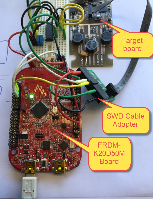
So here is a working prototype based on the FRDM-K20D50M:
FRDM-K20D50M used as debug probe
The Freescale FRDM boards are using a Kinetis K20 based circuit (see “OpenSDA on the Freedom KL25Z Board“): However, that firmware is not open: the K20 is secured and protected, so the firmware cannot be changed. Newer Freescale FRDM boards like FRDM-K22F2 and FRDM-K64F do have an open source bootloader and debug firmware (see “DOC-100720”).
So: take a Freescale Kinetis K20 ARM Cortex-M4, the open source bootloader and firmware, shrink everything to the size of a Teensy board, add headers both to debug the K20 and an off-board microcontroller, and we have tiny board which can be used as a standalone versatile microcontroller board: usable for small projects or usable as debug probe.
Features and wish list:
- Universal, tiny, breadboard friendly which can be used by students for their own projects and which can be used in courses and lab work.
- Freescale Kinetis K20 device, ARM Cortex M4, running up to 50 MHz, powerful enough for most tasks
- 128 KByte FLASH, 16 KByte RAM
- USB connector (both power and connectivity)
- Optional battery power
- Optional real time clock
- Reset/User button
- LED
- Breadboard friendly pin out, all pins available on the outside
- SWD debug interface to debug the onboard K20
- Ability to debug off-board devices with OpenSDAv2
- Small size, around 40×25 mm (TBD)
- Low cost (TBD, less than $<20, depends on quantity)
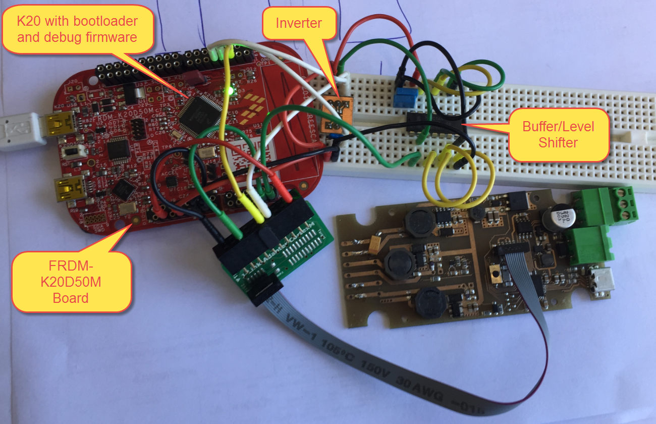
To prove the concept, we used the FRDM-K20D50M board, added buffers/level shifter and an inverter, hooked everything up to a SWD cable, loading the bootloader and debug firmware, and we are able to use it as a debug probe:
FRDM-K20D50M Board
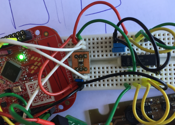
Level Shifter and Inverter
Things are working with the proof-of-concept bread board wiring. Next step is to condense this into a real custom board. If successful, this would be a cool board students can use for their own projects. The next phase will be to design the schematics and the layout for the board. Will post progress, and until then, let me know what you think about this idea to create such a board.
Happy Probing 🙂
Links:
- FRDM-K22F board and schematics: http://www.freescale.com/webapp/sps/site/prod_summary.jsp?code=FRDM-K22F
- FRDM-K64F board and schematics: http://www.freescale.com/webapp/sps/site/prod_summary.jsp?code=FRDM-K64F
- FRDM-K20D50M board and schematics: http://www.freescale.com/webapp/sps/site/prod_summary.jsp?code=FRDM-K20D50M

When you say “All pins available on outside”, are you meaning all of the controller’s I/O pins?
LikeLike
yes, all the microcontroller pins.
LikeLike
Great Idea. I did a first pass cct with a PCB layout as an addition to a PCB board to checkout what worked – just the basic SDA with standard 10pin 0.05″ JTAG. However haven’t got around to building it or testing it yet. It wasn’t clear that the software was stable and build able on KDS 2.?
LikeLike
The bootloader right now is built with Keil tools and is the ‘mbed’ one. The plan is to move this to use open source tools (KDS with GNU) instead.
LikeLiked by 2 people
Erich, I think this would be a great project. The spec sounds a bit like McHck, they also did a SWD adaptor https://mchck.org/blog/2013-08-13-self_hosted_toolchain_the_mc_hck_as_swd_adapter/
I did a simplified design of McHck and had some boards made, but I haven’t got round to populating them yet. The K20 series are great chips, the one thing they lack is a ROM bootloader.
LikeLike
Yes, similar idea. But we want to use a normal micro USB connector on the board instead of the PCB connector, just to make it more user friendly. I was thinking to have an optional break-apart PCB connector, but we need to see if this really makes sense.
I have not seen any more activies on McHck since 2013.
LikeLike
The latest version has a regular connector https://github.com/mchck/mchck/wiki/Schematic-and-layout. What activities were you expecting to see? The design is there, it works…
LikeLike
Pingback: TinyK20 Open Source ARM Debug/Universal Board – First Prototypes | MCU on Eclipse
Pingback: tinyK20: New Board with micro-SD Card | MCU on Eclipse