
For this last blog in the series Investigating ARM Cortex® M33 core I decided to explore the expansion features of the LPC55S69-EVK. This board has three expansion ports (PMOD, Arduino Duo, Mikroe click) and I picked the Mikroe expansion port. Why? Only because I had good experience with these boards with the Hexiwear project.
And because I have been doing some work this month with AWS IOT I wanted to get my LPC55S69-EVK onto my office WiFi network for the Christmas holidays. I know that the MCUXpresso SDK for lpcxpresso55s69 version 2.6.3 has a built-in WiFi example named qca_demo, and so that is what I am investigating today.
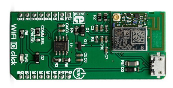
That WiFi example supports three WiFi shield boards, and I picked the Mikroe WiFi 10 click board. It’s part number MIKROE-3432 and available from all of the usual catalogue distributors.
It was a very simple matter to plug the board into the LPC55S69-EVK, and then import the qca_demo project into MCUXpresso IDE with the SDK Import wizard. I’m still using MCUXpresso IDE v11.0.1 and SDK v2.6.3 (but both have been updated this week – 24 December 2019 at the time of writing this blog).
And it was ridiculously easy to get the board onto my office WiFi network. Out of the box the qca_demo example is built for a different shield board. And so (following the guidance in the readme.txt file with the project) I modified the header file wifi_shield.h with a #define for the WIFI10CLICK shield:

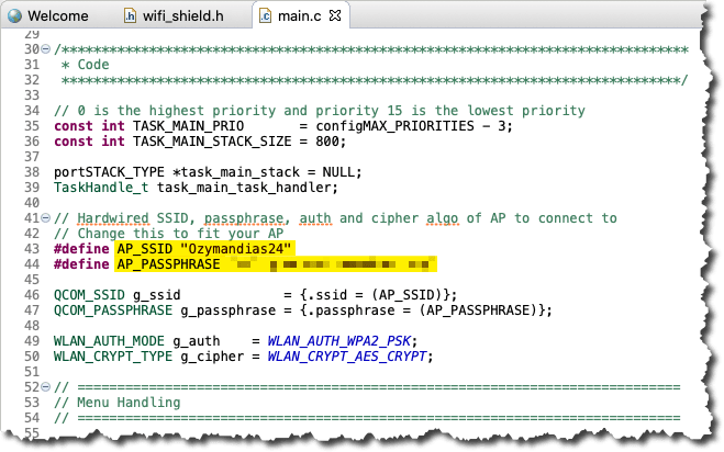
The demo also is hard-coded to support a specific WiFi SSID and the necessary passphrase. It is set in the main.c source module, and of course it is necessary to modify this for my office WiFi network. Again, these are configured as #defines for the project:
Well, that was all that is necessary to get WiFi up and running! The project builds to about 140 kbytes of code (.text section) and about 25 kbytes of RAM (.bss section) in the debug build with no optimisation, and build for debug console through the UART. It is downloaded to the board via the inbuilt LPC-LINK2 debugger on the LPC55S69-EVK and when it runs, qca_demo sets up a command line interface (“CLI”) through the UART.
The readme.txt file in the project defines the commands that are implemented by the CLI. Here is some output from the board listing the commands, and the output from the board when I’ve run the ‘s’ Scan command. The board reports two WiFi networks, one of which is my office network Ozymandias24.
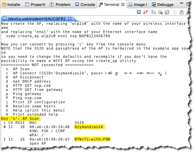
The command sequence ‘s’, ‘c’, ‘d’ will scan, connect and then get an IP address via DHCP from my office WiFi access point. Thereafter the demo illustrates some typical ‘internet’ protocols such as ‘p’ IMCP echo request, ‘g’ HTTP Get request on port 80, and ‘R’ DNS resolve.
I cannot express how quickly and easily I was able to get this board onto my WiFi network. Kudos to NXP and Mikroelektronika for a job well done!
You can watch me unbox, install and connect the WiFi 10 Click board to my office WiFi network in this week’s video. And there are 17 other videos to enjoy on the embeddedpro YouTube channel.
This is the last video in the series. I’m working on some plan for future videos and so, if you have any suggestions for future investigations, or comments on this video, then please leave them below. And (hint) the more likes the blogs and videos get, the more time I’m going to spend on the next series…
I wish you all a peaceful, successful 2020…. Mark, embeddedpro®.

Hi mark,
Thank you for the complete teaching.
After reading your teaching, we want to use LPC55S69 + Wifi 10 click board to connect to AWS IoT, the connection method is MQTT + TLS1.2, but I don’t know if it is feasible? Or can you provide other suggestions for us to refer to?
Thank you!
York
LikeLike
Hi Mark,
I just found an issue on NXP community that the QCA Demo has been removed from the SDK.
https://community.nxp.com/t5/MCUXpresso-SDK/Why-was-WiFi-QCA-removed-from-SDK-2-9-0-for-LPC55s69/m-p/1222401#M3036
Michael
LikeLiked by 1 person
Hi Michael,
I believe this is because NXP acquired a competitor of it?
LikeLike
Hi Mark,
Thank you for your tutorial. I am building an experimental platform using the LPC board and WiFi 10 click board. Do you know any ways to identify the MAC address of the WiFi board? It is required to join the network at my institution. Thank you for your attention.
LikeLike
Did you check the Silex documentation and API? It has an API to get the MAC address of the module, both with UART and SPI.
LikeLike
Hi Erich,
Thank you for your information. I found a command and API specification about the Silex SX-ULPAN-2401 LAN module (used by WiFi 10 Click). Here is the link:
https://cdn2.hubspot.net/hubfs/205257/docs/137-20131-300A-SX-ULPAN-2401-Command—API-Specification-SC106520XC.pdf?t=1521831509214
Now the problem is, I don’t know how to send commands to WiFi Click. Should I have a UART or SPI connection to the LPC board if I want to send commands to the Silex? Then use the LPC board as an intermediary to send instructions through the computer? Or can I directly connect the WiFi Click to the computer through other methods, and then send commands through PuTTY? Sorry, I am new to embedded development, please point out if there are mistakes. Thank you so much
LikeLike
In that case, you have a very, very steep learning curve ahead of you. As the click board is using an SPI connection, you have to program the LPC with functions to read/write from the SPI bus. Then you can implement a gateway over UART or USB to communicate with the module.
I recommend that you start with a simpler thing: check out the NXP SDK examples and learn from there.
Good luck!
LikeLike
Thank you so much, Erich. I have started to learn how to use the LPC board for SPI communication, and it feels good for now. But I am not sure what’s the meaning of “implement a gateway over UART or USB to communicate with the module”. From my understanding, the gateway should be software between the LPC board and desktop; then, I can send commands from the desktop, relayed by the LPC board, and arrive at the WiFi module. After that, the result can be back using the same route. Would you please correct me if there is anything wrong? Thank you very much.
LikeLike
I understood you wanted to talk from the host machine to the WiFi module. In that case you need on the device some firmware (a gateway) translating say the USB commands to the SPI commands to the WiFi module and the same way back again.
LikeLike