By default, the NXP S32K144EVB and microcontroller is using a 5V supply voltage and logic levels which is great for noisy environment or any 5V devices. Many of my displays and sensors use 3.3V logic levels, so I would have to use a level shifter from 5V to 3.3V. There is another way: to change the board for 3.3V logic levels so I can use directly things like a SSD1306 display.
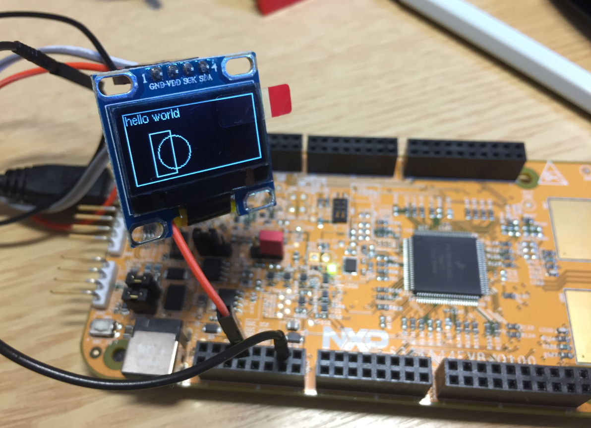
S32K144EVB with OLED SSD1306 using 3.3V Logic Levels
The board schematic overview shows a VDD selection:

S32K144 EVB VDD Selection
In the schematics this is implemented as shown below:

S32K144EVB power Supply Selection
With the R64 (0 Ohm resistor) the board is hard-wired to use 5V (P5V0 to VDD which is the CPU supply voltage). So all what I would need is to remove R64 and install a jumper on J10 to switch between 5V and 3.3V.
Removing R64 is easy with SMD de-solder tweezers tips.

Desoldering tweezer tips
But the through holes for J10 are filled with solder, it seems the board manufacturing data used the wrong solder mask :-(.

Filled holes for J10
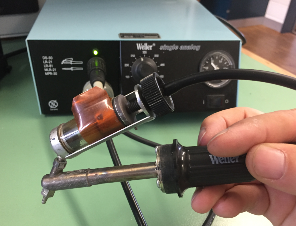
Weller Desoldering Station
After painfully removing the solder from HDR J10, I was able to install a 3-pin header:

Removed R64 and added J10 on S32K144EVB
With a jumper on 1-2 I have no 3.3V:

S32K144EVB J10 Jumper place for 3.3V VDD
Another solution would have been to use a solder bridge between 1-2, but having a jumper is a much nicer way, and I can revert back to 5V VDD if I have to.
Happy Leveling 🙂
PS: that project for the SSD1306 OLED display is available on GitHub.

Hello Erich.
i+It’s the same for the FRDM-K64F?
LikeLike
Hi Juan,
no, the K64F is a 3.3V microcontroller and cannot be used with 5V. Some Kinetis have ‘5V capable pins’, but I never have used that, as only a few pins implement this. I rather use a 5V CPU or a level shifter if needed.
LikeLike
Hi Erich.
In this case, e.g FRDM K64F, is necesary using a logic converter like this:
https://learn.sparkfun.com/tutorials/retired—using-the-logic-level-converter/hardware-overview
For example for interfacing with 5V H-bridges like:
https://www.sparkfun.com/products/10182 ??
LikeLike
Done ! Thanks for the tip; Erich.
The strange things regarding I2C, is that the default configuration uses the flexio interface.
LikeLike
I believe it is using FlexIO for demo purposes.
LikeLike
Hi,
I am using RDDRONE-BMS772 board. There is s32k144 48 pack MCU on it. There is also ssd1306 128×32 display oled on the card. I am running your code by editing it. I turn on the RGB led on the card, but the screen does not work. 3.3 Volt goes to the screen. I see that I2C communication does not start in the logic analyzer. Can you help me with this?
Best Regards!
LikeLiked by 1 person
I checked that board online (I don’t have that one), but I don’t see any SSD1306 on it? If you do not see any I2C communication, I guess you did not properly initialize the I2C peripheral or used the wrong pins?
LikeLike
Hi,
Thank your reply.
I’m sure I chose the pins correctly. If you look at the schematic of the card, they connected an I2C 128×32 display to the J23 in the new version. In this link, they ran the RDDRONE-BMS772 card with NUTTx. https://github.com/NXPHoverGames/RDDRONE-BMS772/blob/main/BMS772_releaseNotes_5.0.pdf
I am writing the software on 2018.R1. I chose the iseled_freemaster_s32k144 project from the sample projects and made corrections by taking your software as an example. I am using the 128×32 part in the software. 3.3 volts is coming to the Vcc pin of the display. There is no problem with the pins. I also set the pins of my processor in the software.
I can turn the RGB LED on and off. But there is no movement on the screen.
I don’t get any errors in the software. When I debug, I can read the GPIO pins. But I can’t read LI2C pins. I see a question mark (?).
I wonder if there is an error in the sample software I chose? I would be very happy if you could help me with this.
LikeLiked by 1 person
Yes, it could be that your sample software/project configures things in the wrong way. Most issues with I2C not working is because of missing/wong I2C pin muxing, or that the I2C hardware clock gate is not enabled, causing the peripheral not working because it is not clocked.
LikeLike
I couldn’t solve the problem but thank you for your reply.
Best Regards!
LikeLiked by 1 person