
This article is about a project I have started back in January 2018. As for many of my projects, it took longer than anticipated.But now it is working, and the result is looking very good: a DIY automated pick and place machine to place parts on circuit boards. In the age of cheap PCBs, that machine closes the gap for small series of boards which have to be populated in a time consuming way otherwise.
OpenPnP Pick&Place Machine
Outline
This DIY machine can populate circuit boards with SMD/SMT parts. If you are wondering, what this is: it is about putting Surface Mounted Devices (SMD) on a Printed Circuit Board (PCB). I gave a talk at the Embedded Computing Conference 2018 on this subject (ECC18 Styger – PickAndPlace mit OpenPnP).
The following videos give an overview about the current state of that machine:
The motivation of building such a machine is that at the university we are populating boards by hand:
Solder gets placed on the boards (stencils are rarely used):
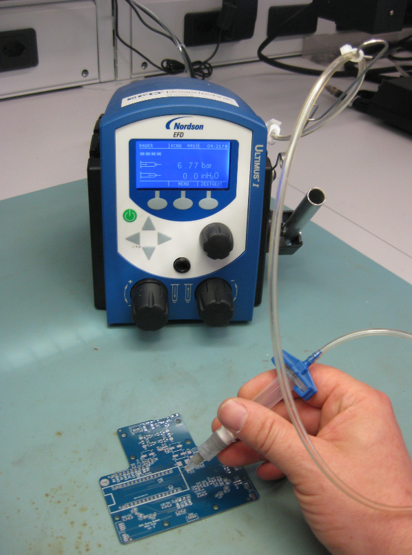
Applying solder
Solder paste on PCB
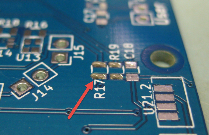
Then parts get placed on the boards

manual placing
We do have as well vision support for the manual placing:

manual placing with vision

Resistors placed on PCB
And finally they run through a reflow oven:
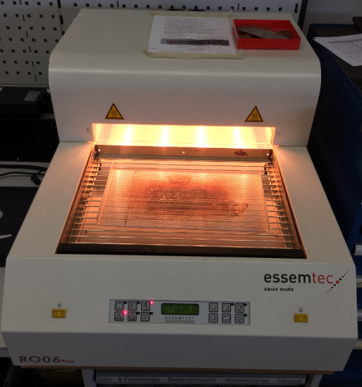
Reflow Oven
That’s all working fine. The problem is that this all takes a lot of time. Doing it for one board is one thing, but doing it for 10-50 boards takes too much time. Clearly, for mor than 50 or 100 boards, outsourcing is the logical choice. But for a few boards as we usually have to do, outsourcing is not the best option as it is expensive and takes a lot of time too.
What I wanted is a machine to automate the manual placing of components. Such a machine is called a ‘Pick and Place’ machine: it picks parts and places them on a PCB.
DIY Pick & Place Maschine: OpenPnP
When searching for such Pick&Place machines, I stumbled over the OpenPnP project at http://openpnp.org/: A open source community and project which builds such machines. So I thought: why not building one myself too? And here we go :-).
OpenPnP offers a framework to run such a machine. They have guides and tutorials how to build such a machine. And it is up to you how you build it and what features get added. I did not want to build the fastest or the cheapest machine: my goal was to keep the hardware costs below $1000, and that the machine is able to place parts down to the 0402 size.

SMD Sizes
All the software and BOM are available on GitHub (see links section at the end of this article).
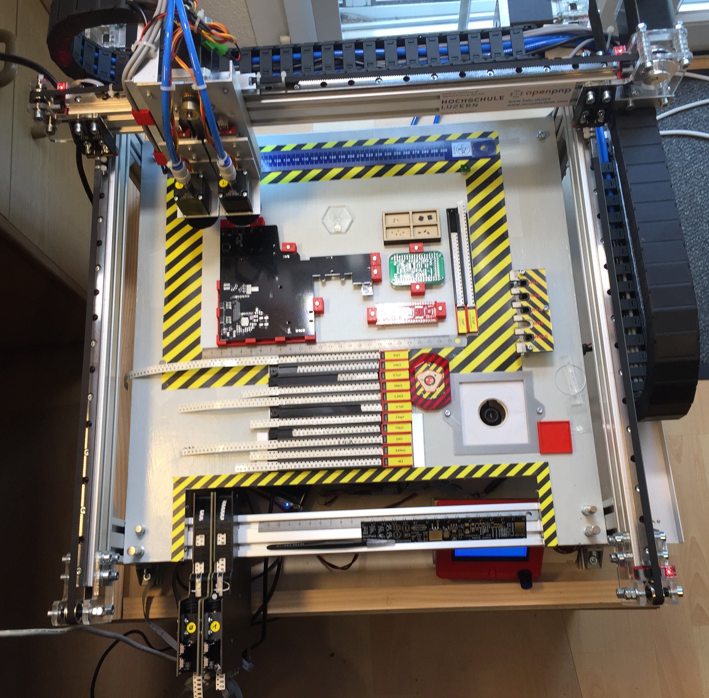
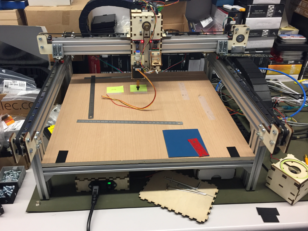
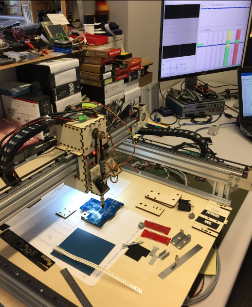
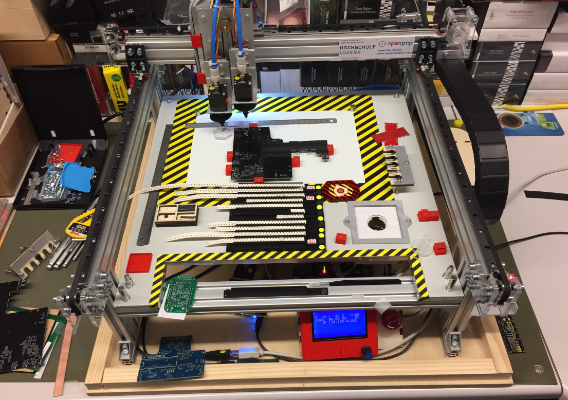
The machine uses 24V stepper motors for X, Y and Z axis. Two smaller stepper motors on the head (C1, C2) can be rotated. Attached to the head is a down-looking camera.
Integrated in the work area are nozzle changers, a bottom camera and different feeders.
Under the base plate all the other electronics (solenoid, pump, USB Hub, feeder and controller board with LCD and power supply.
CAD (KiCAD, Altium, Eagle) data is loaded on a host PC running OpenPnP.
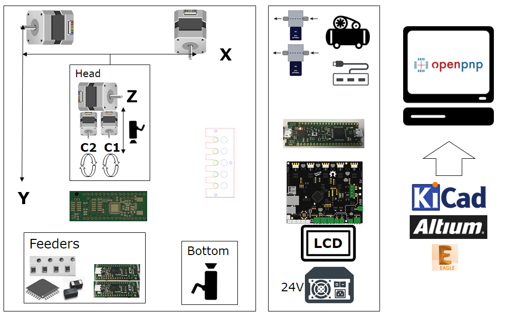
System Overview
Below are pictures of the machine under construction with some details. I hope this gives you ideas and an inspiration to build your own machine.
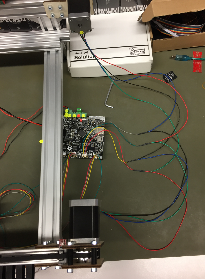
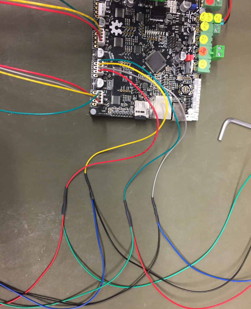
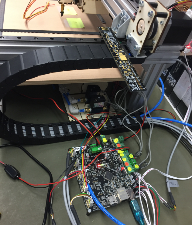
Microcontroller
The heart of the machine is the NXP LPC1769 on the Smoothieboard:

NXP LPC1769
It is responsible for all the sensors and drives all the motors. The picture below shows first tests with a stepper motor:
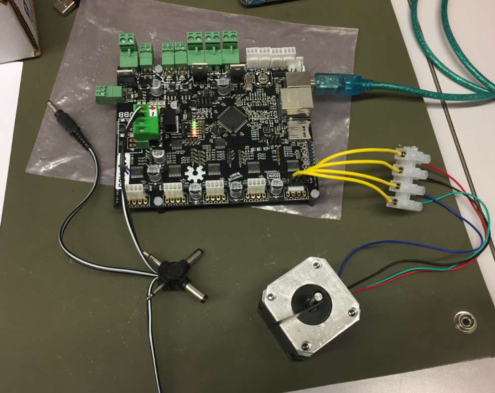
first stepper
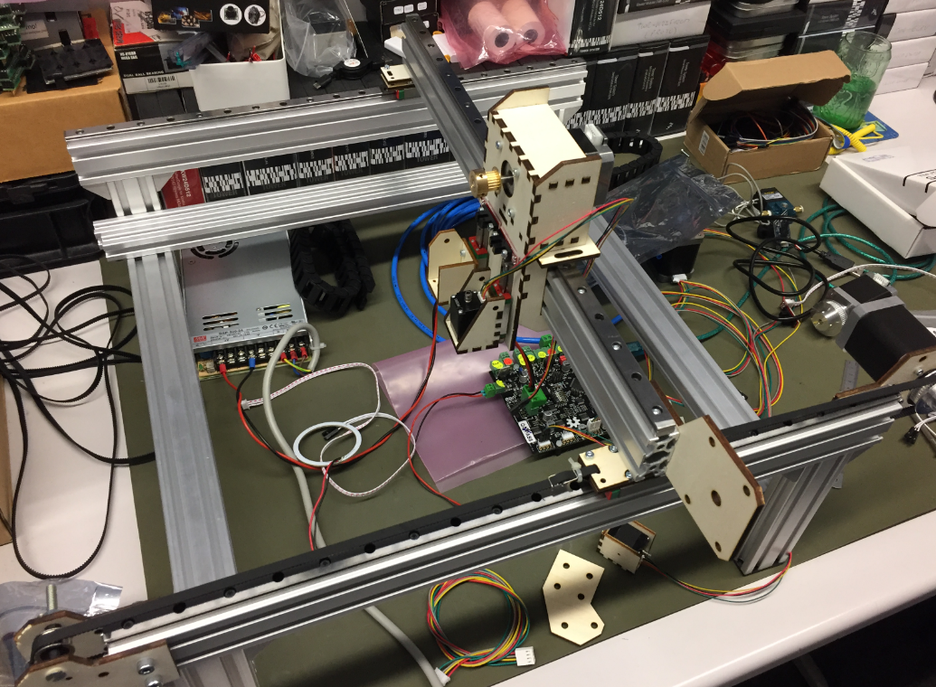
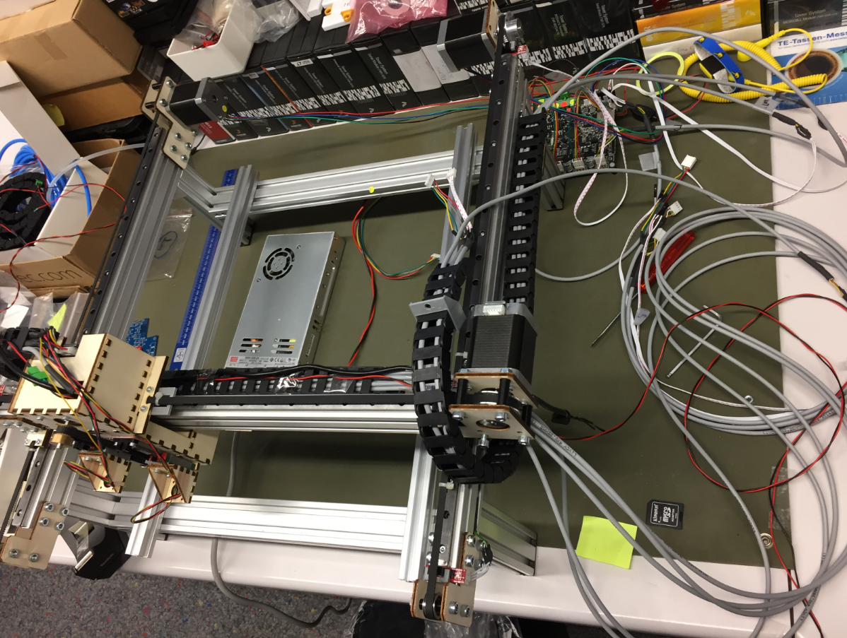
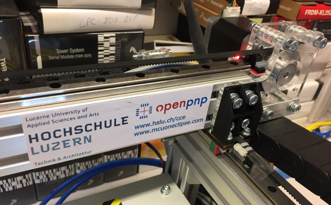
Frame
The frame is constructed with 20×20 and 20×40 standard aluminum extrusion profiles:
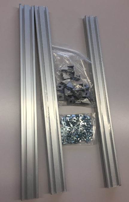
Aluminium
The profiles allow an easy construction of the frame.

Aluminium Frame Construction
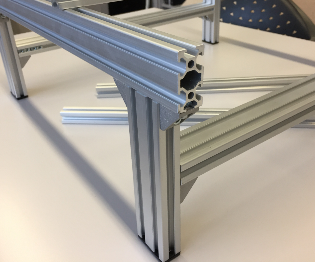
2040 Profiles
Rails
The linear rails arrived very well oiled and in good shape.
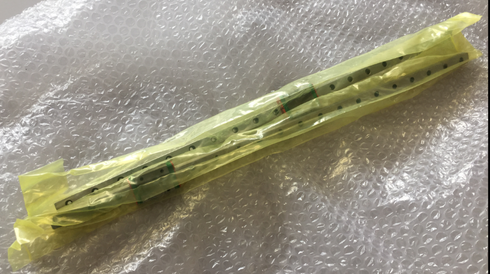
Linear Rails arrived
The rails get attached to the top of the frame:

Rail mounted on frame
It has been an iterative process, and many parts first have been built with a laser cutter and plywood. Below is a picture of an early version:
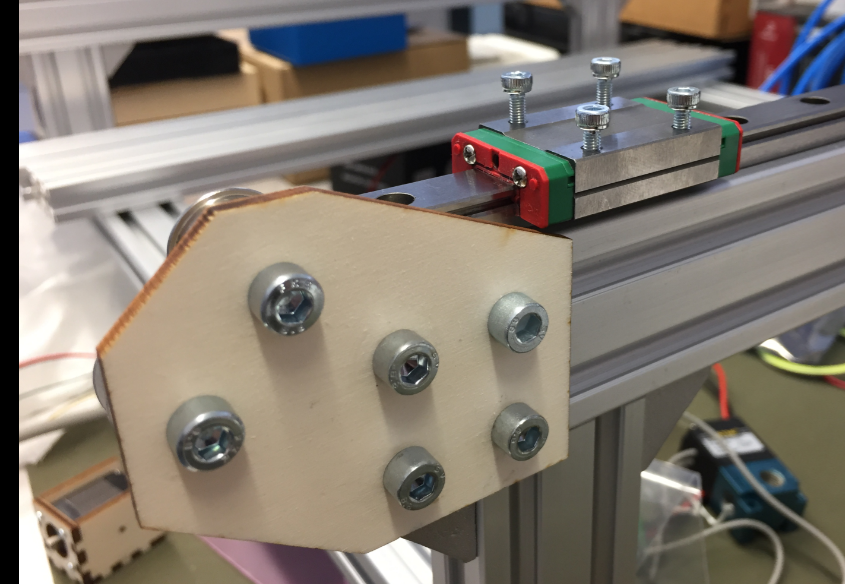
Rail with end bracket
Vacuum Pump
Actuators in the system are 24V. Below is the diaphragm vacuum pump used for the nozzles:
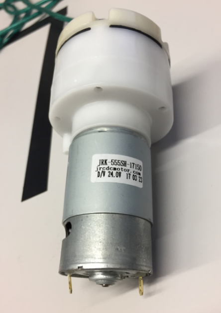
24V Vacuum Pump
Terminals of the pump:

Vacuum Pump Connectors
The pump together with the two high-speed solenoid on a base plate. To reduce noise, the pump has been placed into a box standing on anti-vibration feet:
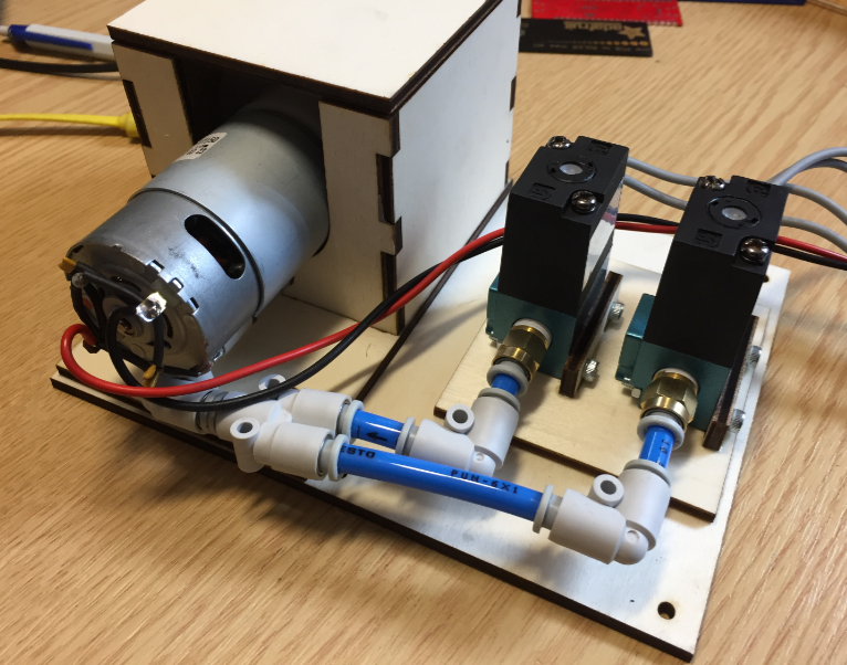
Pump with enclosure

Pump Top View
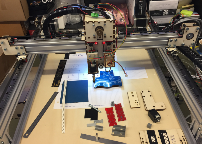
Below a first test with three stepper motors:

Bench
Power Supply
For the 24V 13.4A Power supply I added an on-off switch with integrated fuse holder:

Power Supply with On-Off Switch
Flyback Diodes
As flyback diodes for the pump and solenoids I used the Vishay BYV27-200-TAP:

Protection Diodes
Vacuum Valves
I’m using the STNC TM-06 high frequency valve (24VDC) with 1/8″ pipe connectors:

STNC TM-06 Valve
Below how they are connected to the board with the flyback diodes mounted to the connectors:
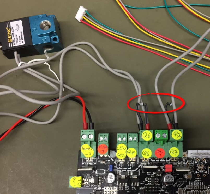
Protection Diodes for Solenoids
For example the M813 G-Gode turns it ON (2-1 connected), and M812 turns it OFF (2-3 connected). The image below shows the air flow:

STNC Directions
That means the vacuum pump will be on connection 1 and the nozzle on connection 2, with connection 3 used to release the vacuum.
End Stops
The total of 6 end stops are optical ones:

End Stops
The first (not ideal) way to mount the end stops:
First way for endstops
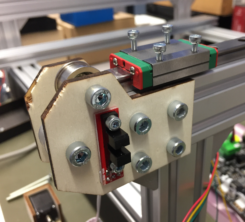
Second version of end stop mounting with 3D printed holder:

3D Printed End Stop Holder

3D Printed End Stop Holder back side
Mounted End Stop

3D Printed End Stop Parts
3D printing end stop blades:
3D Printing End stop Blades
Mounted end stopper blade:

Mounted End Stopper Blade
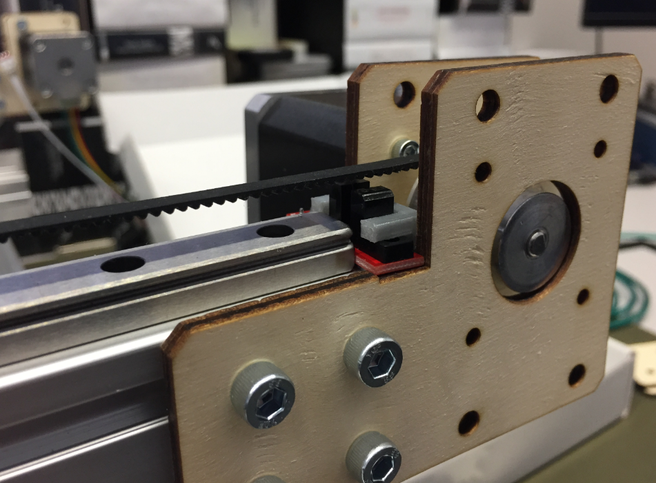
In a next step lowered the end stop position:

Lowered End Stop Position

Belt and Endstop
Pick and Place Head
Very first version of the head:
First Pick Head
Holder for the pick stepper motor:

Holder for the Pick Stepper Motor
Rails for the pick head steppers:

Pick Head Rails
Frame with first pick head:
Frame with first pick head
Pick head with end stops:

Pick Head with End Stops
Because the X axis was not rigid enough, 3D printed brackets were added:

3D Printed Bracket
X-Y-Rail

Mounting Bracket for X-Y Rail
T-Nuts on X-Y Rail:

T-Nuts on X-Y Rail
Y Steppers
Two stepper motors wired together are driving the Y axis. It works, but I would not recommend that approach: better use a single motor with an extended shaft and coupling.
Wiring of Y motors
Y Stepper Wiring
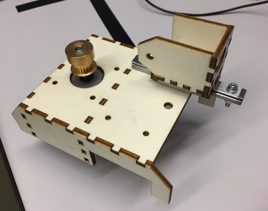
Laser cutting the motor and pulley brackets:
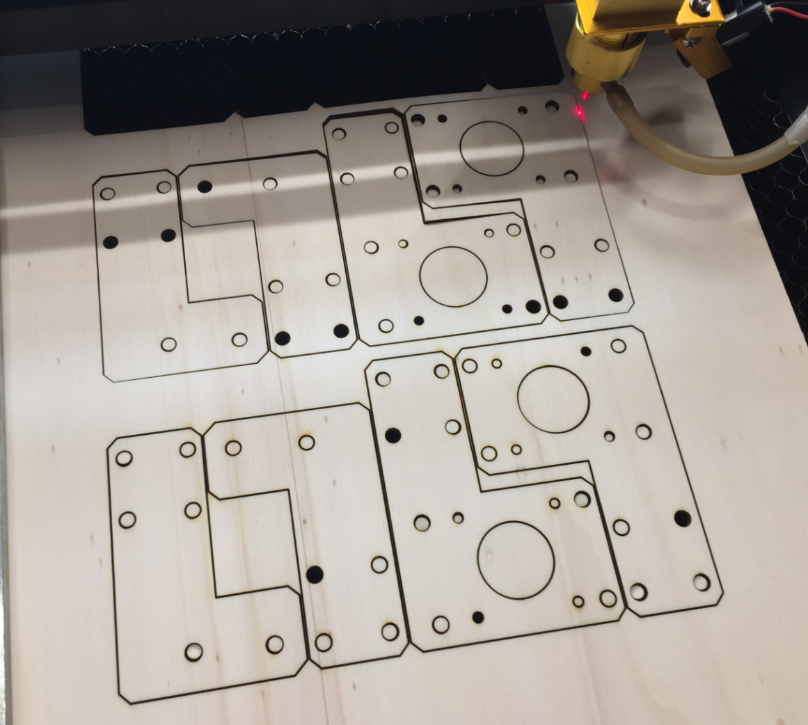
Laser Cutting Motor Brackets
Of course it was an iterative process, and many design ideas did not end up in the final machine. The good thing with plywood is that it is cheap and is easy to construct with it.
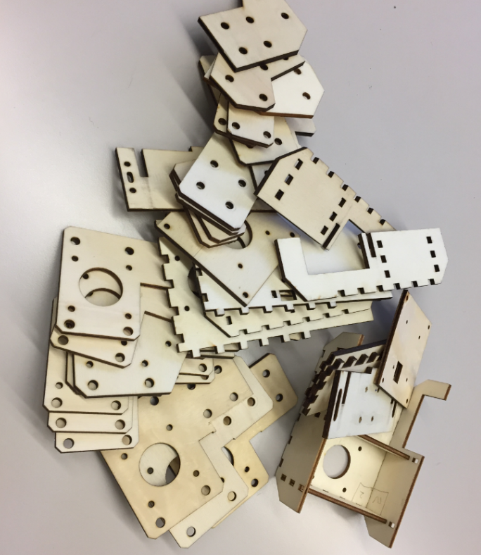
Pile of plywood
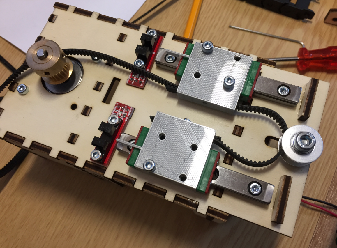
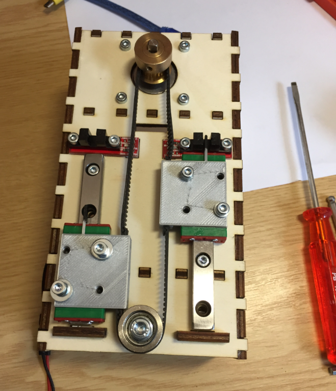
Second Pick Head Design
The second version of the pick head was more compact and easier to attach to the linear rail.
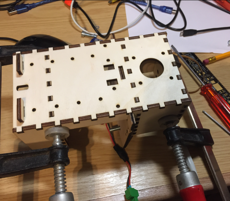
Assembling the Pick Head
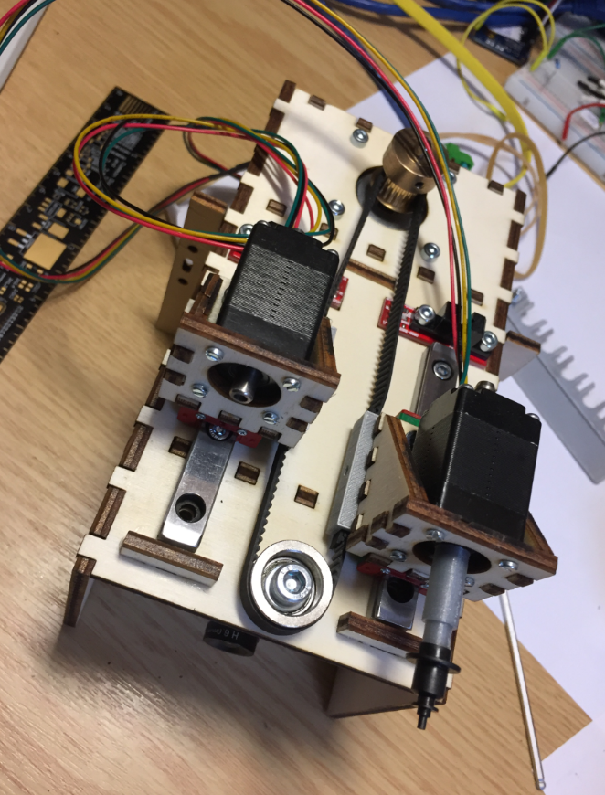
Below the head attached to the X axis:

2nd Pick Head
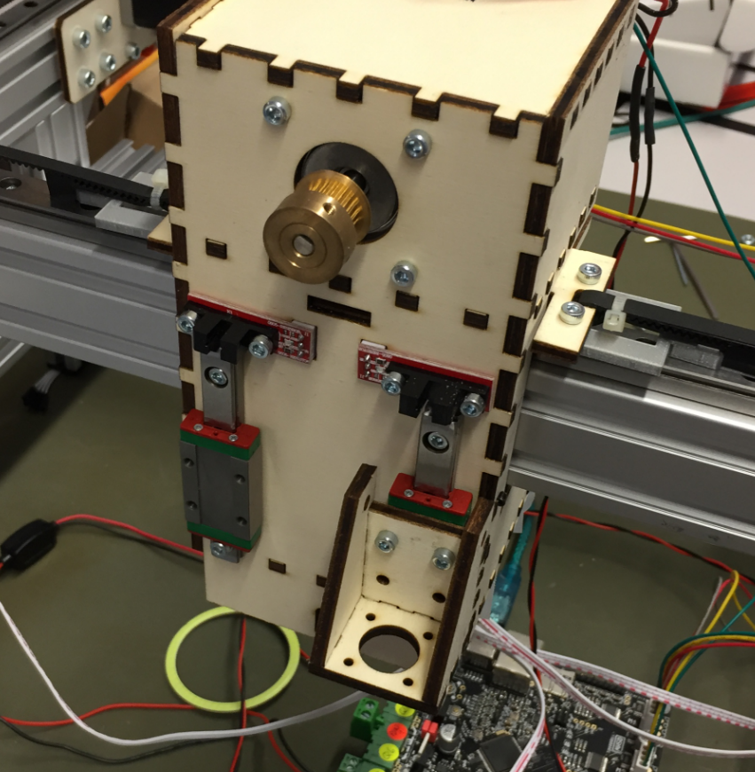
Pick Head 2nd Version
Below an early version of the head with no cable chains attached:

Head without cable chains
I used 3D printed parts to attach the heads with the Z axis belt:
Z-Axis Belt with 3D printed parts
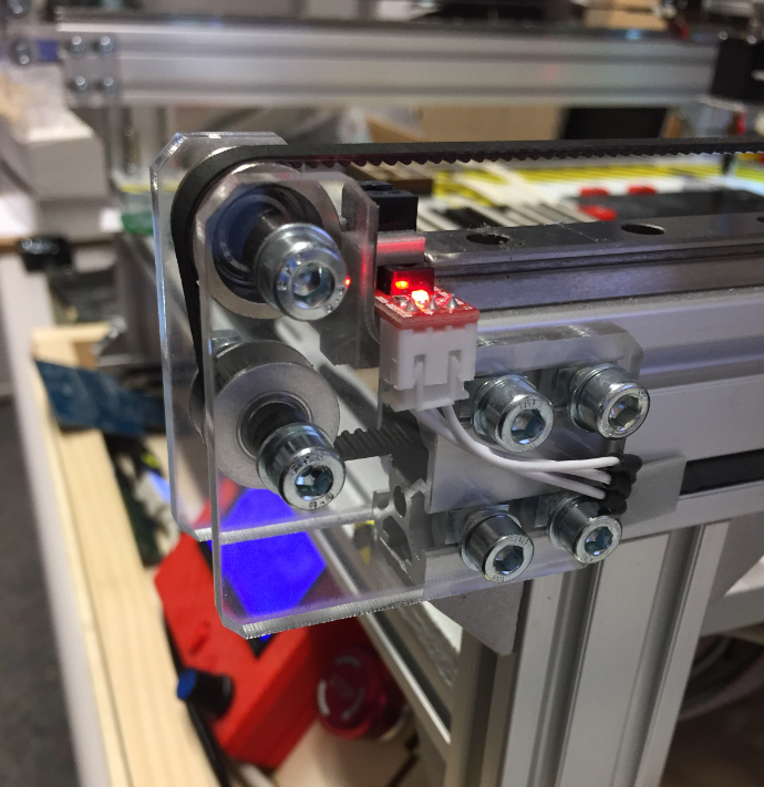
The belt is attached to the linear rails using a press-fit connection, and the connector acts as an end stop the same time:

Press-Fit Belt Holder
Here with the rails, belt and endstop mounted:
Head Rails and Endstops mounted
Here the head with the pick heads:
Pick Heads
Downlooking Camera
Below an early design of the downlooking camera integrated into the bottom of the head:

First version of downlooking camera
First down camera and light tests:
First Camera Tests
First Camara and LED ring holder:
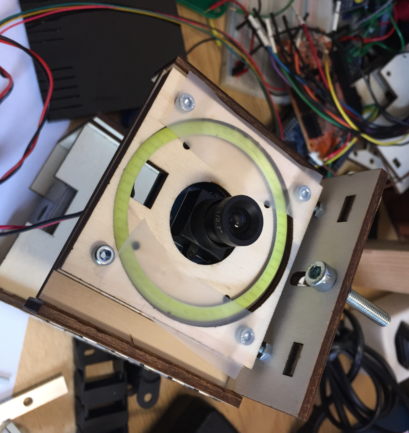
First Camera Holder
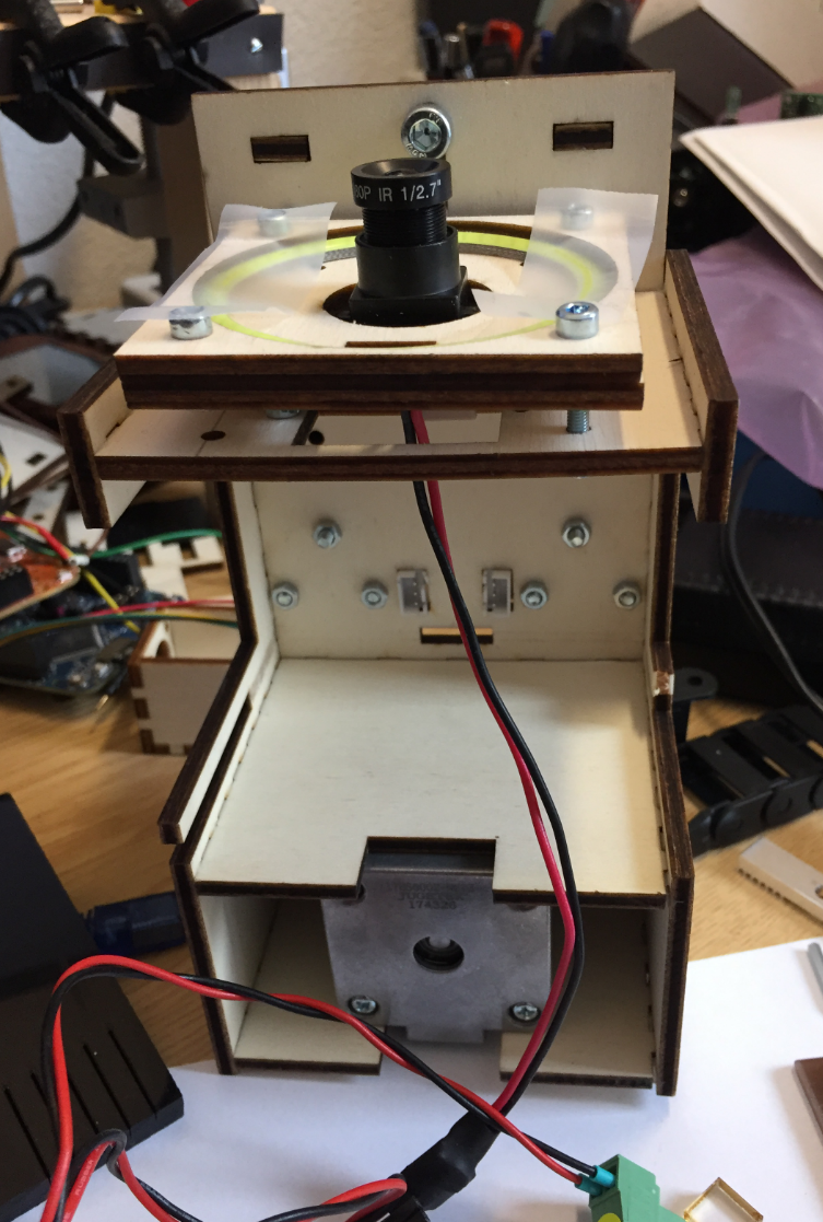
Head with Camera Holder
A plexiglass with a sheet of whiter paper acts as diffuser:

LED Ring diffuser
Pick heads with downlooking camera:

Pick Heads with downlooking camera
Mounted head with first cable chains:
PnP Machine
Metal Pick Head
The next iteration oft the pick&place had is a version built with aluminium profiles. The first step was to use aluminium profiles for the head mounts:
Aluminium Head mounts

Aluminium Motor Mounts
Then the head backplane has been built with aluminium profiles:

Aluminium Profile Pick Head
That way the head was more sturdy than the one made of plywood.

Aluminium Profile Head
Below with the hollow shaft stepper motors mounted, plus a cable chain for the end stops, LED ring and camera USB cable on the left:

Aluminium Profile Pick and Place Head

Machine with Metal Head
Nozzle Holder
Nozzle Holder, magnet holds the nozzle:

Nozzle in Holder

Nozzle and Nozzle Holder
Improved nozzle holder with 1.5 mm space between the plates and acrylic on the top:

Nozzle Holder with Acrylic
Nozzle Holders mounted on base plate
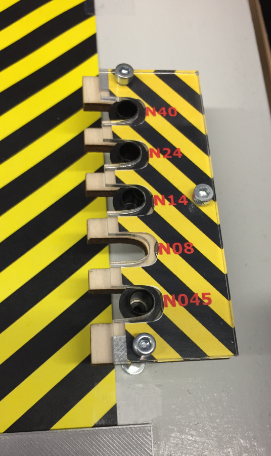
NozzleHolderLabel

Different Nozzles
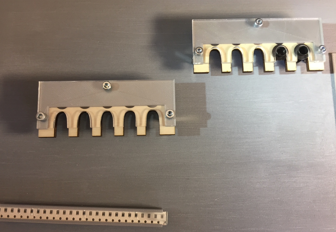
Cut Tape Holder
See 3D Printed SMT Cut Tape Holder for more details.

SMD Strip Holder

Cover

Tape Holder with Magnets

Tape Holder 3D Model

SMD Tape Holder
Feeder
The automatic feeder is designed by Simon Huber. The goal was to create a feeder for SMD parts on rolls.
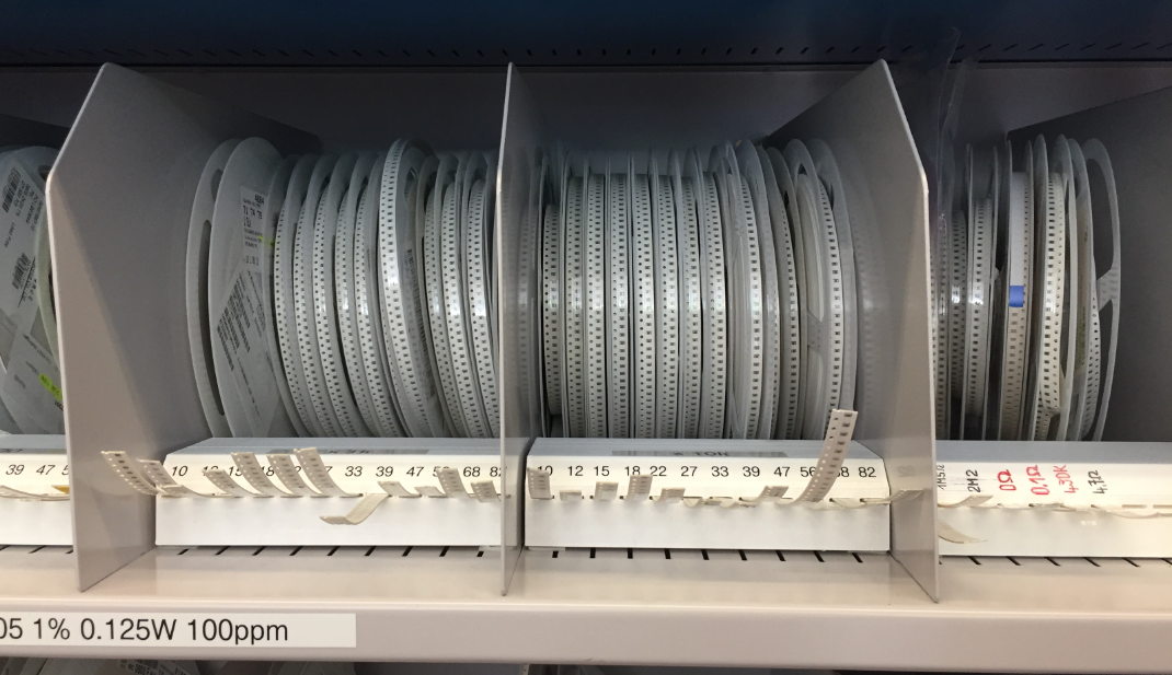
SMD Resistors
The feeder uses 3D printed parts:

3D Printed Feeder

Feeder with SMT Tape
Each feeder uses a NXP K20DX128 (ARM Cortex-M4) as the controller:

AutoFeeder
One DC motor moves the tape and one DC motor peels the cover:

Feeders removing cover
A tinyK20 (NXP K22FN512, ARM Cortex-M4) receives M-Codes from OpenPnP and passes them to all feeders:

tinyK22
The feeders are in a daisy chain, and the machine has space for up to 16 feeders.
Nozzles
The first nozzle stepper motors did not work well. The M5 screw did not match the stepper motor hollow shaft. The designed adapter had too much wobble and was not usable.
First Pick Head with Nozzle Adapter
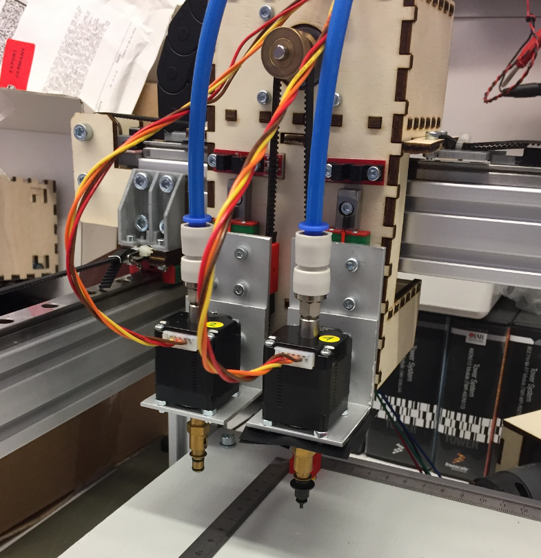
So I had to put aside the nice and small hollow shaft stepper motors. I ordered new (bigger) ones so I can easier attach the nozzle changes and a vacuum tube connector on the back. The new motors had on both sides an M5 screw so I can attach rotation tube adapters and attach easily the nozzle adapter.
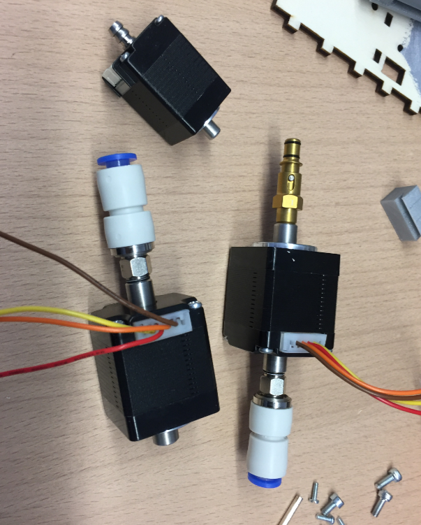
New Nozzle Stepper Motors
Because the motors were bigger, I had to create new motor holders:

New Nozzle Motor on the head
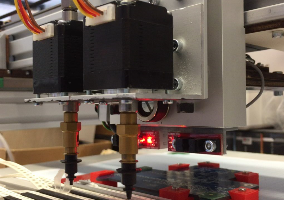
Pick Heads
Cable Chains
The first cable chains were too small to hold all the tubing and cables, so a new one has been installed.Below the machine with the first (too tiny) cable chains:
PnP Machine with small cable chains
Small cable chain attached to the head:

Small cable chain attached to the head

Machine with small cable chains

Machine with second version of head
New cable chains arrived:
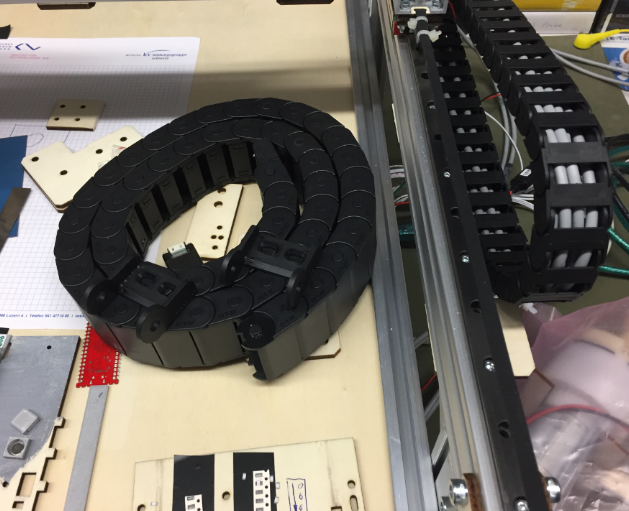
New Cable Chain arrived
That larger (40×15 mm) was able to keep all the cables and tubing.

Bigger Chain holds it all
Below with the new chain attached to the head:

Head with new cable chain

Cable Chain
Side View with Cable Chain
Base Plate
Machine with new base plate
The bottom plate with cutouts for the feeders and the bottom camera:
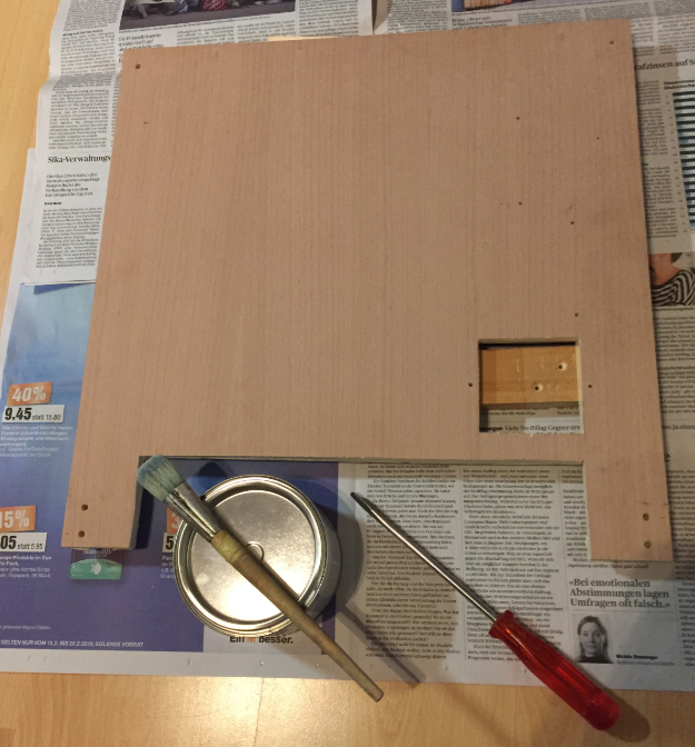
Base Plate ready for paint
It gets painted with three layers of magnetic paint:
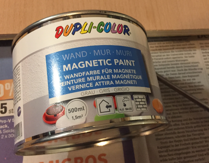
Magnetic Paint

Painted Base Plate with Magnetic Paint
Bottom Camera
Laser Cutting the Enclosure for the Bottom Camera
Assembling the bottom camera enclosure:

Assembling bottom camera enclosure
Assembled bottom camera case:

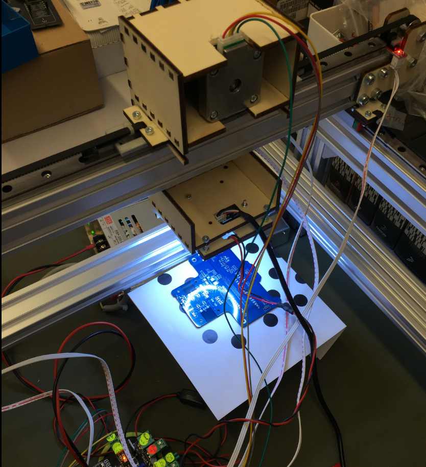
Bottom Camera Enclosure
Testing the camera:

Testing the Bottom Camera
Up camera mounted into base plate:

Uplooking Camera (Bottom Vision) in Base Plate
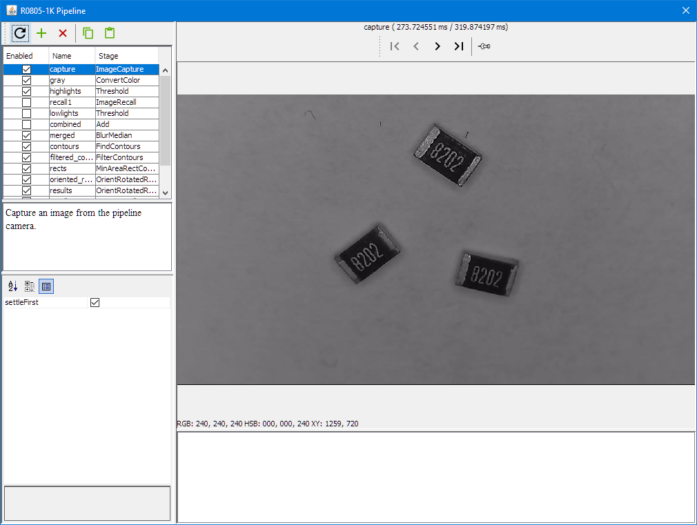
Bottom Vision
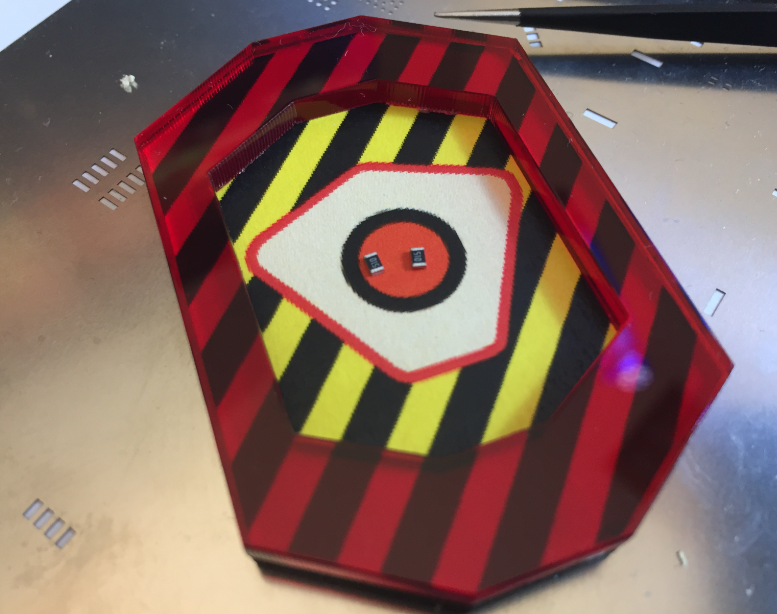
With the bottom camera, OpenPnP can move a part over the camera to correct angle and position with the vision system:

Bottom Vision Capture
It uses a vision pipeline, below with a blur filter applied:
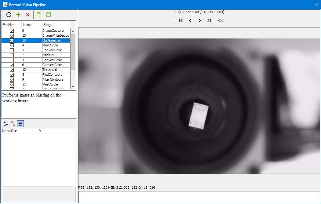
Bottom Vision Gaussian Blur
Masking:
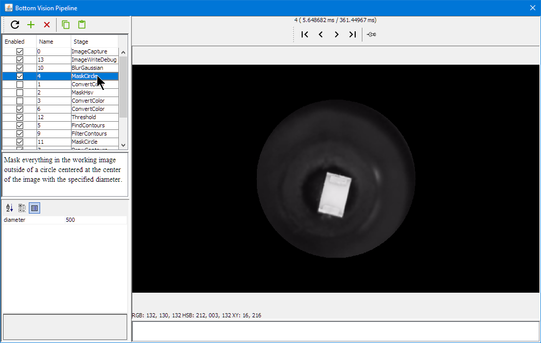
Bottom Vision Circle Mask
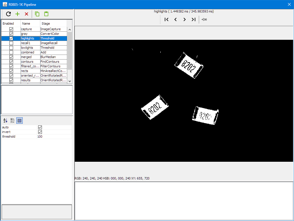
getting the part outline:

Bottom Vision Threshold
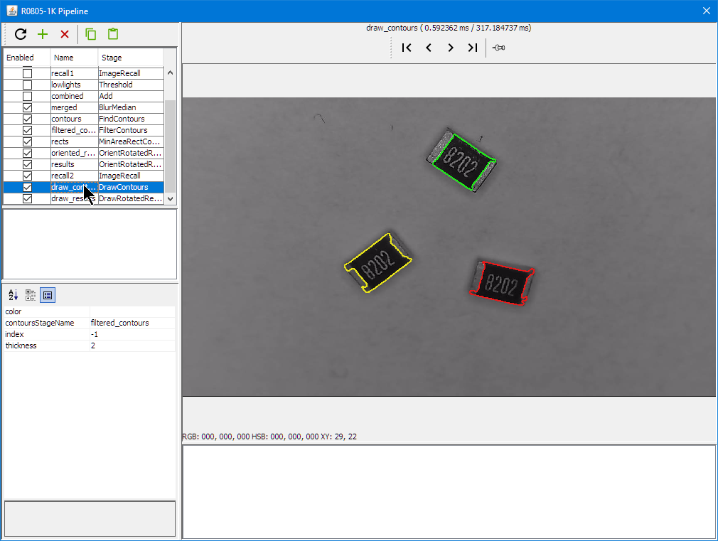
Getting the contours:

Bottom Vision Draw Contours
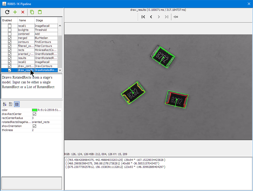
Detecting part position and angle:
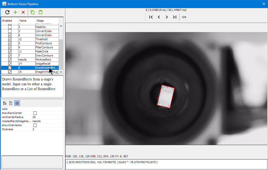
Bottom Vision Rotation Rectangle
OpenPnP includes a loose part feeder: parts can be put into a bin and the vision system can identify it:
LoosePartsFeeder 1
LoosePartsFeeder 2
LoosePartsFeeder 3
LoosePartsFeeder 4
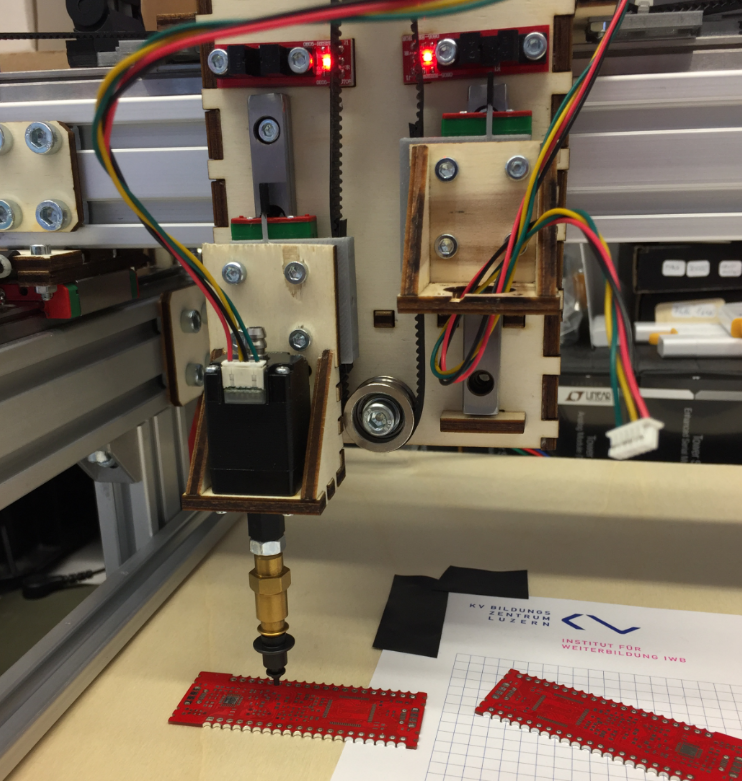
PCB Holder
As the top camera has rather small focus area, I need to keep the feeder pick (see “3D Printed SMT Cut Tape Holder“) height and the PCB surface on the same height. For this I have created 3D printed magnetic PCB board holders.

3D Printed PCB Holder with Red PCB

3D Printed PCB Holder
Graphic LCD
Similar as for my laser cutter (see “Upgrading a Laser Cutter with Cohesion3D Mini and LCD“) I added a graphics LCD to the board.

Machine with LCD Display
http://smoothieware.org/rrdglcdadapter describes the settings and installation of a graphics LCD on the Smoothieboard.
I decided to order an adapter board from 3DWare:

GLCD Adapter Board Top Side
Below the bottom side of the board:
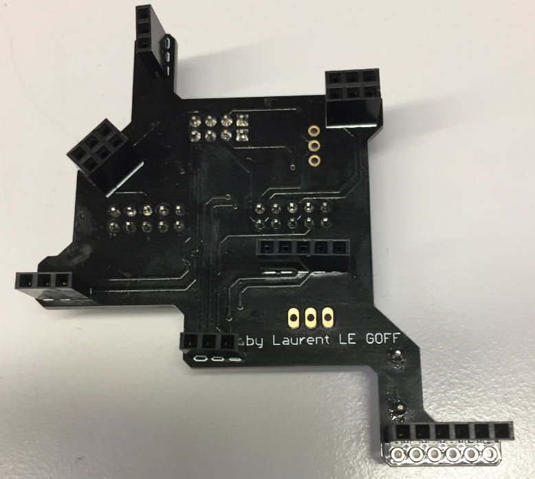
GLCD Adapter Board Bottom Side
Below how the adapter board is installed on the board:
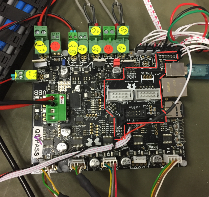
Location of GLCD Adapter on Smoothie
Below the display attached to the board and working :-):

Smoothie with GLCD
Below the (still messy) electronic parts on a base plate:
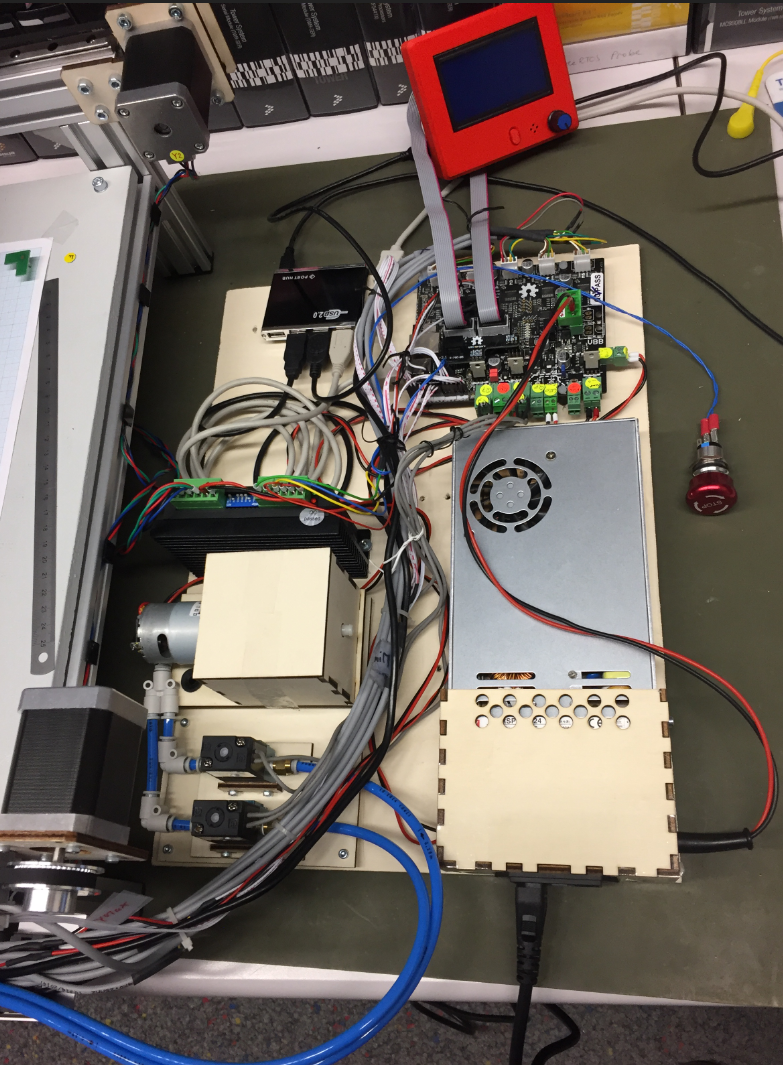
Electronics
Added to the display is an emergency stop button. Below the connection to the controller board:
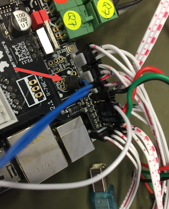
Emergency Stop Connection

LCD with Emergency Stop
OpenPnP Software
The OpenPnP software runs on the host PC.
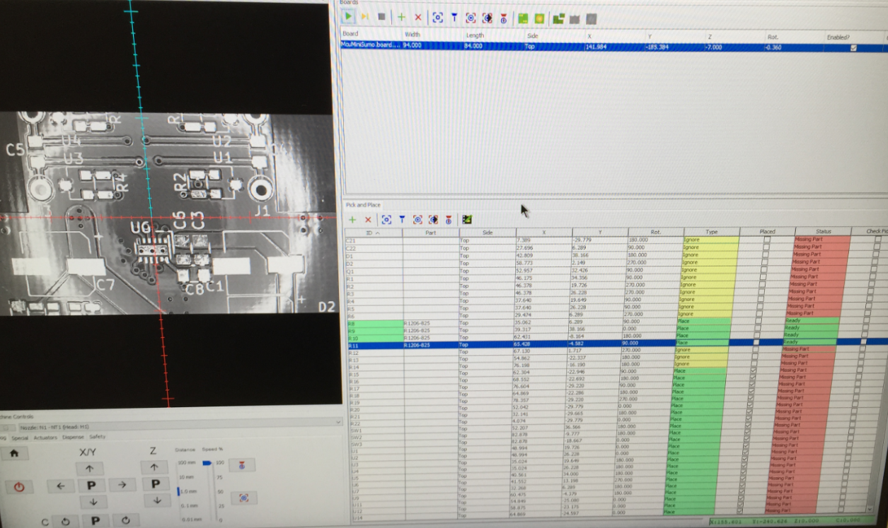
OpenPnP Software
The host PC does all the image processing and sends commands to the machine.
Running an OpenPnP Job
Drop Box
For bad parts or to drop parts, OpenPnP can use a dedicated ‘drop area’. for this I created a custom (laser cut) drop box: It uses 3mm red acrylic on the top:
PnP Drop Container
4mm plywood on the bottom with magnets so it sticks to the machine surface:

PnP Drop Container with magnets
Plexiglas Brackets
The motor and belt brackets originally were cut out of plywood: here I replaced the 4mm plywood with 5 mm laser-cut plexiglas ones which looks nicer :-):
Plexiglass PnP Bracket
X Axis with Plexiglas/PMMA motor bracket
The machine mounted on a 16mm plywood base plate:
Mounted on BasePlate
Summary
It has been a fun project, and the machine works well, but still needs some tuning. I plan to add a solder paste dispenser: that way, if no stencil is available, the machine can add the solder paste to the pads on the board. Another thing is to use pressure sensors to monitor the vacuum for each nozzle. And for the motor auto-feeder I would like to update the design. So there is always something to improve. Currently the machine can place around 500-600 parts per hour down to 0402 size. With this and little setup, we can run small board series successfully.
PS: a big “thank you!” to the OpenPnP community: without all their work and contributions, such a project would not have been possible.
Happy Picking 🙂
Links
- Files of my machine on GitHub: https://github.com/ErichStyger/McuOpenPnP_Machine
- Presentation at the Embedded Computing Conference 2018: http://www.swisst.net/files/swisstnet/de/dokumente/ECC/ECC18/Referate/3C2_Styger_HSLU.PDF
- 3D Printed SMT Cut Tape Holder
- Smoothieboard hardware on GitHub: https://github.com/Smoothieware/Smoothieboard
- Smoothieboard configuration options: http://smoothieware.org/configuration-options
- Smoothieboard supported G and M codes: http://smoothieware.org/supported-g-codes
- Smoothieboard extruder: http://smoothieware.github.io/Webif-pack/documentation/web/html/extruder.html
- LinuxCNC G-Code List: http://linuxcnc.org/docs/2.6/html/gcode/gcode.html#_g_code_quick_reference_table_a_id_quick_reference_table_a
- Reprap G-Code List: http://reprap.org/wiki/G-code
- STNC TM-06 24V valve: https://www.robotdigg.com/product/566/High-frequency-Solenoid-Valve-12-or-24VDC
- GLCD Adapter board: https://www.3dware.ch/Adapter-LCD-s-GLCD-f%C3%BCr-Smoothieboard-De.htm
