
So here I have 50 new NXP Kinetis K22 Robot boards (see “Zumo Robot with Magnetic Encoders“), and they all need to be programmed with the first firmware on the bench:

Programming Robot Boards
The challenge is: how to do this in a fast an efficient way, without the need for an IDE or even host PC machine?
Programming many Boards
The reality is: We do not only need to program these new robot boards: we usually re-program the boards we used in classes every semester to have a ‘clean’ board status.
Well, I could program the boards with my laptop, the IDE (e.g. Eclipse) and a debug probe. Done that several times for a few boards. But that gets painful for more than a handful boards. The next level is to use a script file as in “Command Line Programming and Debugging with GDB“. But still, this needs a host machine plus some level of operator skills.
Still, with many boards and many classes, this gets very painful. I would like to delegate it to someone working at the bench. Without the need to setup or reserve a laptop or other host machine, without the need to deal with different tools and the needs to explain the process every time. What I need is something else: a standalone flash programmer.
Standalone Programmer
I’m not the only one with that kind of problem. Board assembler and assembly lines have the same (well, even larger) problem: they need to program many boards in an easy (automated way). There are different and multiple solutions available for this on the market, e.g. from P&E and Segger.
What we are using is the Flasher ARM. It is basically an advanced version of a J-Link with extra interfaces (LAN and RS-232) and 64MByte memory to store images and scripts to program ARM microcontroller with the push of a button:

Segger Flasher ARM
The Flasher comes with a 20pin ribbon cable, serial cable, ethernet cable, USB cable and a 5V 700mA USB power supply (more about this later).
💡 The kit does not include a 10pin SWD adapter, so I’m using the one I have for my J-Link EDU (green PCB and cable shown in the picture below).

Comparison J-Link and Flasher ARM
The Flasher has three interfaces: USB, RS-232 serial and Ethernet, and supports three programming modes:
- J-Link mode: I can use it like a normal J-Link debug probe. In this mode the probe is connected to the host e.g. with the USB cable.
- Standalone mode: I can program boards with the press of the ‘Start’ button, or I can use the serial port e.g. connected to SPS or other microcontroller to start and check the programming. This is what I would use in a manufacturing line environment.
- Mass Storage Device mode: Powering the Flasher with the start button pressed for 2 seconds enumerates the Flasher like a memory stick. In that mode I can configure the device or copy the data files to it. This is useful as for this no special software is needed to configure the Flasher.
💡 Compared to ‘debug’ programmers, standalone programmers offer more advanced features for factory line programming and added scripting and verify operations. Additionally, factory programming usually comes with some certified programming algorithms and checks which usually are not available in normal debug flash programming routines: it would be very bad if devices would fail after a few years in the field if they were programmed with algorithms which are good enough for debugging, but not good enough for flash retention :-(.
Programming Boards with the Flasher
I’m using the ‘Standalone’ mode with the push button method to program the firmware on the robot boards.
First, I have created an image (S19) (see “Binary (and S19) Files for the mbed Bootloader with Eclipse and GNU ARM Eclipse Plugins“) file of the program I would like to flash to the boards.
With File > Open data file… I load the S19 which then shows up in a memory view:

Open Data S19 file
With the menu Options > Project Settings I configure the process. The first tab is about which connection to use:

Project Settings General
I have the choice between JTAG and SWD and the connection speed:

Project Settings Target Interface
Very important are the CPU settings:
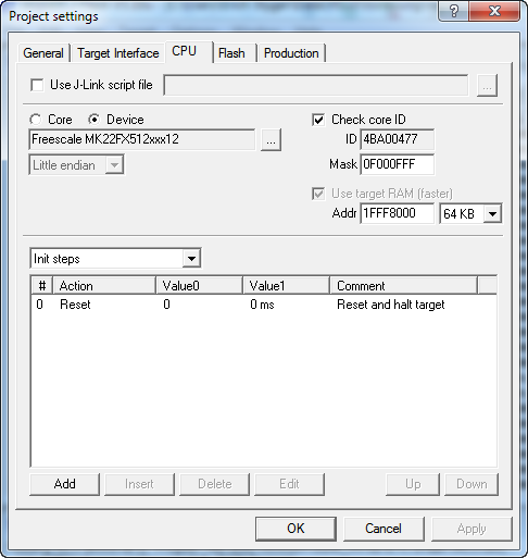
Project Settings CPU
Here I could add extra init or exit steps:

Possible additional init steps
💡 First I was trying to reset the board at the end of the flashing, but there is an easier way in the ‘Production’ dialog.
In the ‘Flash’ tab I can configure the flash sectors of the device:

Project Settings Flash
In the production settings I have configured it to reset the target at the end of the flash programming via reset pin:
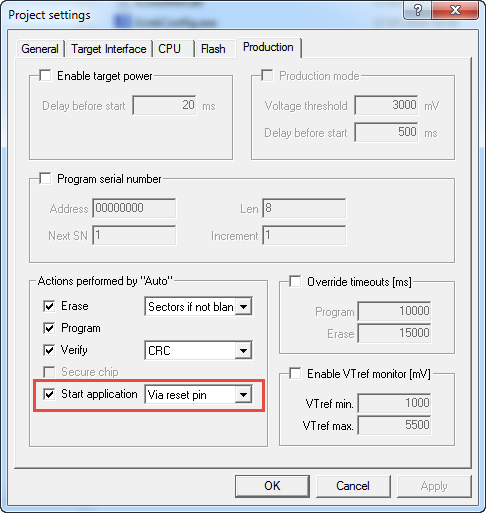
Production Settings
💡 This dialog has a setting about providing target power (5V). I would need 3.3V unless I would make an adapter to the USB port where I could use the 5V.
With Download config & data file to Flasher everything gets stored for standalone programming:
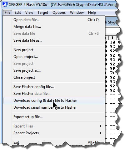
Download config and data to Flasher
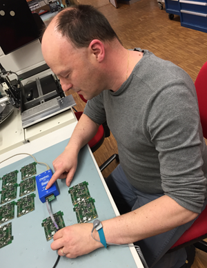
Programming with a Push Button
To program the boards, the Flasher gets powered with the USB power supply included with the Flasher. Another USB power supply is used to power the board:

Bench setup
Now I can program the board with the press of a push button:
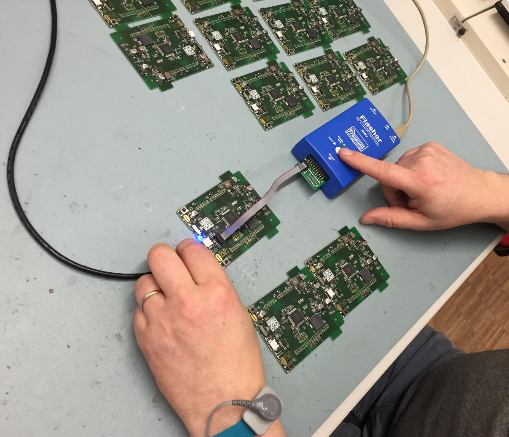
Programming with a push button
Summary
Well, maybe the title of this post is a bit misleading: there is still a host PC involved at the first step to set up the standalone programmer. But after that, no host PC is needed to program the boards. We can set aside the configuration and the image, and using the ‘Mass Storage Device’ mode of the Flasher to load it with new scripts and firmware files.
The Flasher greatly simplifies our process of reprogramming the boards. It is so easy that even I can do it 🙂
Flashing Boards
Could I use a normal debug probe for this? Certainly, but at the price of the setup and the overhead. On the other side, the Flasher has many more advanced features like special erasing, device diagnostics, serial number programming and fully automated factory line programming. I’m not using these right now, but they are worth considering it. Because of these features, such a device is obviously not low cost, but I think still reasonable given the functionality and flexibility they give. As a plus, the Segger Flasher ARM can be used as a normal J-Link too.
Happy Flashing 🙂
Links
- Segger Flasher ARM: https://www.segger.com/flasher-arm.html
- Creating S19 files with Kinetis Design Studio: Binary (and S19) Files for the mbed Bootloader with Eclipse and GNU ARM Eclipse Plugins
- Command line programming with GDB: Debugging ARM Cortex-M Hard Faults with GDB Custom Command

It would be cool if it could program several boards/devices at once by JTAG chaining them together. Is that possible?
LikeLike
I have not done that, but but you certainly can do it according to the manual: you can specify the device on the scan chain, and you can program multiple devices, one after each other on the chain.
LikeLike
Do they explain what sort of “daisy-chaining” JTAG cabling is required to do such bulk programming? Bulk/parallel programming sounds like it might help you given the photo of all those boards on your desk… 🙂
LikeLike
Yes, the J-Link (and therefore the flasher) support J-Tag daisy chaining, but I have not used that myself yet. But that would not have been possible with the boards I have, as they have the SWD on the header only. Chaining JTAG singals is done usually on the board itself, not from one board to another.
LikeLike
I’m going to be looking to use some kind of JTAG daisy-chain programming of Kinetis K22’s soon. I’ll post back my findings should I get it working and the methods/cabling used!
LikeLike
Pingback: Debugging ARM Cores with IP based Debug Probes and Eclipse | MCU on Eclipse
Pingback: Standalone and Command Line Programmer with MCUXpresso | MCU on Eclipse