This is Part 3 of a Mini Series. In Part 2, I described how to set up the development tools and to debug the first project (see “Tutorial: Adafruit WS2812B NeoPixels with the Freescale FRDM-K64F Board – Part 2: Software Tools“). Now it is time to look into the software concepts. The goal is to drive Adafruit’s NeoPixel (WS2812B) with the Freescale FRDM-K64F board:
Adafruit 8×8 NeoPixel Shield with Freescale FRDM-K64F Board
Mini Series Tutorial List
- Tutorial: Adafruit WS2812B NeoPixels with the Freescale FRDM-K64F Board – Part 1: Hardware
- Tutorial: Adafruit WS2812B NeoPixels with the Freescale FRDM-K64F Board – Part 2: Software Tools
- Tutorial: Adafruit WS2812B NeoPixels with the Freescale FRDM-K64F Board – Part 3: Concepts
- Tutorial: Adafruit WS2812B NeoPixels with the Freescale FRDM-K64F Board – Part 4: Timer
- Tutorial: Adafruit WS2812B NeoPixels with the Freescale FRDM-K64F Board – Part 5: DMA
Outline
This article explains the protocol and timing to talk to the WS2812B (or Adafruit NeoPixel) LEDs. It explains an approach with timers and DMA to meet the hardware requirements. I’m using GNU ARM Embedded (launchpad) tools with an Eclipse based IDE (Freescale Kinetis Design Studio v3.0.0). As software drivers I’m using the Freescale Kinetis SDK v1.2.
WS2812 Chaining
The WS2812(B) LEDs have a built-in current driver with a shift register: writing data to the shift register will latch the bits, and the constant current driver will ‘drive’ the current to the Red, Green and Blue part of the LED.
Data is written on a single wire (DIN pin) the first WS2812 in the chain. The first device will ‘keep’ the first 24bits, and everything else is shifted out to the DOUT pin. So to provide data to 2 LED’s, I shift 2x24bits: the first 24bits are for the first device in the chain, then next 24bits for the next in chain, and so on.

WS2812 LED Chain (Source: https://cpldcpu.wordpress.com/2014/01/14/light_ws2812-library-v2-0-part-i-understanding-the-ws2812/)
WS2812 Color Information
Each LED needs 24 bits, encoding the colors Green, Red and Blue with 8 bits each. So it is GRB, not RGB! Each color 8bit determines the brightness of that color, from 0x00 (off) to 0xff (full brightness). the bits are sent MSB (Most Significant Bit) first.
To turn on the red part of the LED at full brightness, with both blue and green off, I have to send the following bits:
0 0 0 0 0 0 0 0 1 1 1 1 1 1 1 1 0 0 0 0 0 0 0 0
To have all (GRB) LED’s with half of the brightness, I send
0 1 1 1 1 1 1 1 0 1 1 1 1 1 1 1 0 1 1 1 1 1 1 1
WS2812 Timing
The WS2812/B need a special timing of these bits. I highly recommend to read Tim’s article (“Light_WS2812 library V2.0 – Part I: Understanding the WS2812“) about the WS2812 timing:

WS2812 Timing (Source: https://cpldcpu.wordpress.com/2014/01/14/light_ws2812-library-v2-0-part-i-understanding-the-ws2812/)
The WS2812B is the never variant, and has slightly different timing. The newer Adafruit NeoPixels are all WS2812B. As the timing has some tolerances, I’m driving it with the following timing for ‘0’ and ‘1’ bits:
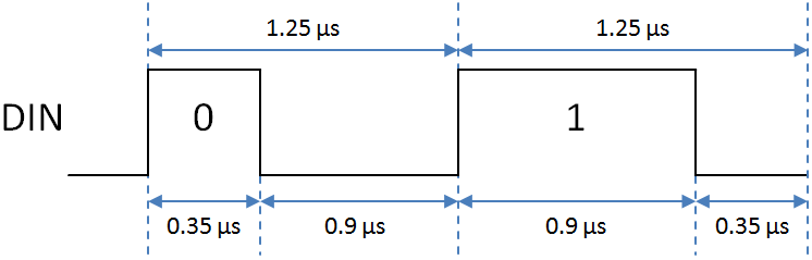
WS2812B Timing
Generating the Bit Stream
There are several possible ways how to generate such a bitstream. One way is to use a GPIO (General Purpose I/O) pin with Bit-Banging (Toggling output pins by normal GPIO port operations):
void Init(void) {
  GPIO_DDR = OUTPUT; /* initialize PORT as output */
  GPIO_DATA = 0; /* bits low */
}

void PutBit(uint8_t bit) {
  if (bit) { /* one bit */
    GPIO_DATA = 1; /* put pin HIGH for 0.9 us */
    WAIT_NS(900); /* wait 900 ns */
    GPIO_DATA = 0; /* LOW for 0.35 us */
    WAIT_NS(350); /* wait for 350 ns */
  } else { /* zero bit */
    GPIO_DATA = 1; /* put pin HIGH for 0.35 us */
    WAIT_NS(350); /* wait 350 ns */
    GPIO_DATA = 0; /* LOW for 0.9 us */
    WAIT_NS(900); /* wait for 900 ns */
  }
}
An even improved version is to avoid checking the bits:
void PutBit(uint8_t bit) {
  GPIO_DATA = 1; /* put pin HIGH */
  WAIT_NS(350); /* wait 350 ns */
  GPIO_DATA = bit; /* LOW if zero bit, otherwise remains HIGH */
  WAIT_NS(550); /* wait for 550 ns */
  GPIO_DATA = 0; /* put pin LOW */
  WAIT_NS(350); /* wait for 350 ns */
}

Writing PORT Bits to Generate Signal
Now put all the bits into an array, and stream it out like this:
#define NEO_NOF_PIXEL        2  /* number of pixels */
#define NEO_NOF_BITS_PIXEL  24  /* 24 bits for pixel */
#define NEO_DMA_NOF_BYTES   sizeof(transmitBuf)

static uint8_t transmitBuff[NEO_NOF_PIXEL*NEO_NOF_BITS_PIXEL]; /* WS2812 Bits */

void Transmit(unsigned char bit) {
  int i;

  for(i=0; i<sizeof(transmitBuff); i++) {
     PutBit(i);
  }
}
But the signal frequency is 800 kHz! So Bit-Banging won’t work, unless you are using hand crafted assembly coding to reach the speed and timing. Additionally I would have to disable the interrupts, as any interrupt can screw up the timing too! Turning interrupts off for a few LEDs will work, but the longer the LED chain, the longer the interrupts have to be turned off. Definitely not good enough.
Using a Timer
Instead having everything done in a loop, why not using timer interrupts instead? Basically setting up three timer interrupts firing each at a 800 kHz frequency, with the timing shifted as such that it matches the WS2812 timing. So I can use one timer with three channels: in the corresponding interrupts I could write to the DATA to generated the bit timing:
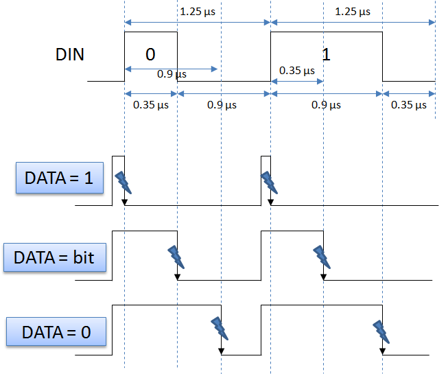
Driving Bits withTimer Interrupt
This is now much better than doing things in a loop. Still it means interrupts happening with 3×800 kHz, or every ~0.35 µs an interrupt! Yikes! My system will be busy with interrupts pretty much all the time: For every interrupt, the CPU needs to stack the registers, change the contect to the interrupt service routine, performe the operations to the DATA register in the routine and return back to the original context. A lot of operations!
Using DMA
So if toggling a pin is too slow, using interrupts creates too many interrupts, why not finding a way to have it faster? The solution to this is DMA (Direct Memory Access). DMA allows todo operations without using the CPU. DMA allows me to read/write memory (and more), and is like a kind of co-processor.
I’m still using that timer. But instead firing interrupts, I will trigger a ‘direct-memory-operation’ in the background, asking to write my data directly to the (memory-mapped) DATA register:

Driving Bits with DMA
That way the operation can happen in the background, without CPU involvement :-). And good new is: many modern microcontroller have DMA capabilities, and the Kinetis K64F on the FRDM-K64F board does have it too :-).
Summary
In this post I explained the concepts behind generating the correct bit stream to drive the WS2812B NeoPixels. As the signal is a high frequency one, I have to utuilize timers with DMA, otherwise the CPU will be loaded too much.
In the next article I’m going to implement the timer with the Kinetis SDK. So stay tuned …
Links
- Understanding the timing of WS2812 and WS2812B: https://cpldcpu.wordpress.com/2014/01/14/light_ws2812-library-v2-0-part-i-understanding-the-ws2812/
- Adafruit Guide on NeoPixels: https://learn.adafruit.com/adafruit-neopixel-uberguide/overview
- Freescale Freedom FRDM-K64F Board: http://www.freescale.com/webapp/sps/site/prod_summary.jsp?code=FRDM-K64F
- Freescale Kinetis Design Studio: http://www.freescale.com/kds
- Freescale Kinetis SDK: http://www.freescale.com/kds

Pingback: Tutorial: Adafruit WS2812B NeoPixels with the Freescale FRDM-K64F Board – Part 2: Software Tools | MCU on Eclipse
Pingback: Tutorial: Adafruit WS2812B NeoPixels with the Freescale FRDM-K64F Board – Part 1: Hardware | MCU on Eclipse
Thanks Erich, another great article 🙂
LikeLike
Pingback: Tutorial: Adafruit WS2812B NeoPixels with the Freescale FRDM-K64F Board – Part 4: Timer | MCU on Eclipse
Pingback: Tutorial: Adafruit WS2812B NeoPixels with the Freescale FRDM-K64F Board – Part 5: DMA | MCU on Eclipse