
I’m using the RS-485 field bus in many of my projects: it is very reliable and robust, and easy to implement. And with ModBus there is standardized protocol used in building automation or industrial control applications. For example I’m using the protocol to communicate between battery systems and an EV Charger.
In this article I show you with an example, how the NXP LPC55S69 can be used with RS-485.
Outline
In this article, I describe how to use the LPC55S69-EVK for communicating over RS-485 (and ModBus if you like). To get you quickly started, I have put an example project on GitHub.
RS-485 is basically a half-duplex serial protocol (like UART) over two wires, with a differential signalling. With a simple protocol or ModBus, it can address and talk to individual nodes on the bus. Because the signal is differential, it is suitable for longer distances up to about 1000 meter, implementing a wired network with multi-drop capabilities.
Wiring
In most of my RS-485 projects I’m using the TI SN65HVD72 bus transceiver:
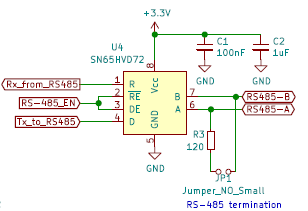
The bus is terminated on each end with a 120 Ohm resistor with a jumper. To have defined states (e.g. in case of disconnected wires, I usually add optional jumpers for pull-ups and pull-downs as in the schematic below:

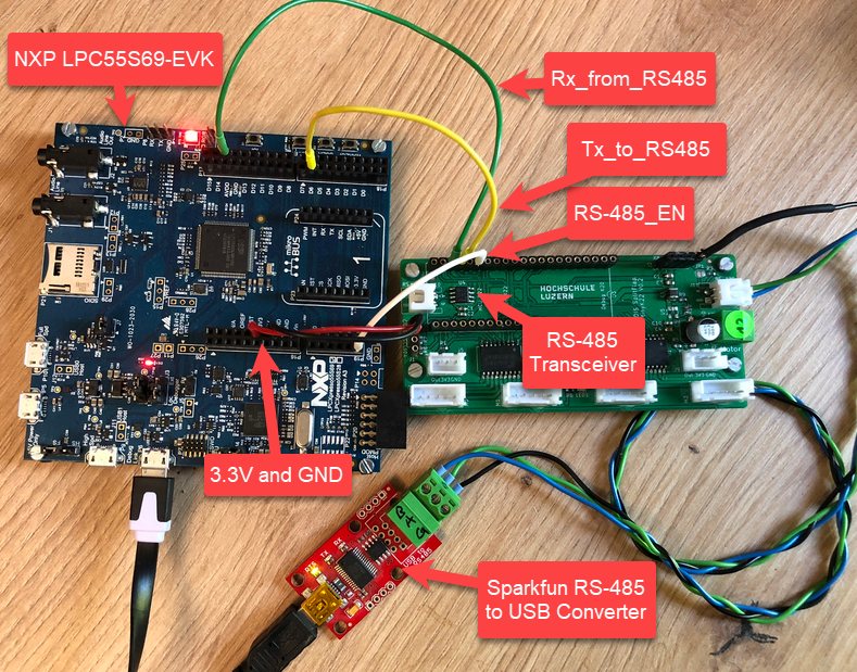
In the picture below I have connected the LPC55S69-EVK with the SN65HVD72 transceiver on the green board, and the RS-485 A/B and ground wire is connected to the Sparkfun RS-485-to-USB-CDC converter board I’m using in other projects too.
Muxing
On the LPC side I’m using the UART with FLEXCOMM1, below is the muxing for the Rx, Tx and RTS lines:
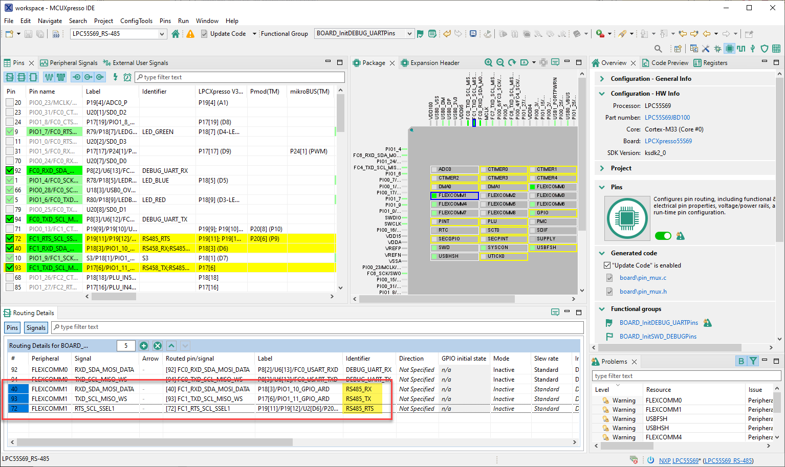
The RTS line is used to toggle the RS458_EN line, which puts the transceiver into Rx or Tx mode. In the driver the RTS can be configured to be automatically set by the UART, or toggled manually as a GPIO pin. The enable (or RE/DE on the transceiver) is HIGH active while sending:
McuLib
The project uses the McuLib on top of the MCUXpresso SDK. The McuLib is a cross-platform driver and utility collection.

The RS-485 driver is inside McuLib\src\McuUART485.c, and configured through McuLib/config/McuUart485config.h
Configuration
The driver is configured through macros which can be overwritten or extended.
Below is the main configuration:
/* ---------------------------------------------------------------------------------------*/
/* McuUart485 */
#define McuUart485_CONFIG_USE_RS_485          (1) /* enable RS-458 driver */
#define McuUart485_CONFIG_USE_MODBUS          (0) /* not using Modbus for now */
#define McuUart485_CONFIG_USE_LOGGER          (1) /* add ability to log data to the console */
#define McuUart485_CONFIG_UART_BAUDRATE       (115200) /* baud rate */
#define McuUart485_CONFIG_USE_HW_OE_RTS       (1)  /* use UART hardware RTS pin */
Which useds the following driver settings to use FlexComm1:
  /* using FlexComm1, on LPC55S69-EVK this is on pin 40 (Rx, FC1_RXD_SDA_MOSI_DATA, PIO1_10) and pin 93 (Rx, FC1_TXD_SCL_MISO_WS, PIO1_11) */
  #include "fsl_usart.h"

  #ifndef McuUart485_CONFIG_UART_PARITY
    #define McuUart485_CONFIG_UART_PARITY                 kUSART_ParityDisabled /* or kUSART_ParityEven or kUSART_ParityOdd */
  #endif

  #define McuUart485_CONFIG_UART_DEVICE                   USART1
  #define McuUart485_CONFIG_UART_SET_UART_CLOCK()         CLOCK_AttachClk(kFRO12M_to_FLEXCOMM1)
  #define McuUart485_CONFIG_UART_WRITE_BLOCKING           USART_WriteBlocking
  #define McuUart485_CONFIG_UART_GET_FLAGS                USART_GetStatusFlags
  #define McuUart485_CONFIG_UART_HW_RX_READY_FLAGS        (kUSART_RxFifoNotEmptyFlag | kUSART_RxError)
  #define McuUart485_CONFIG_UART_READ_BYTE                USART_ReadByte
  #define McuUart485_CONFIG_UART_CONFIG_STRUCT            usart_config_t
  #define McuUart485_CONFIG_UART_GET_DEFAULT_CONFIG       USART_GetDefaultConfig
  #define McuUart485_CONFIG_UART_ENABLE_INTERRUPTS        USART_EnableInterrupts
  #define McuUart485_CONFIG_UART_ENABLE_INTERRUPT_FLAGS   (kUSART_RxLevelInterruptEnable | kUSART_RxErrorInterruptEnable)
  #define McuUart485_CONFIG_UART_IRQ_NUMBER               FLEXCOMM1_IRQn
  #define McuUart485_CONFIG_UART_INIT                     USART_Init
  #define McuUart485_CONFIG_UART_GET_CLOCK_FREQ_SELECT    kCLOCK_Fro12M
  #define McuUart485_CONFIG_UART_IRQ_HANDLER              FLEXCOMM1_IRQHandler
  #define McuUart485_CONFIG_CLEAR_STATUS_FLAGS            USART_ClearStatusFlags
If McuUart485_CONFIG_USE_HW_OE_RTS is set to zero, it uses a normal GPIO pin to control Rx/Tx on the transceiver:
   /* default: pin 92 on LPC55S69-EVK, routed as FC1_I2C_SCL */
    #ifndef McuUart485_CONFIG_TX_EN_GPIO
      #define McuUart485_CONFIG_TX_EN_GPIO       GPIO
    #endif
    #ifndef McuUart485_CONFIG_TX_EN_PORT
      #define McuUart485_CONFIG_TX_EN_PORT       0
    #endif
    #ifndef McuUart485_CONFIG_TX_EN_PIN
      #define McuUart485_CONFIG_TX_EN_PIN        14U
    #endif
If it is set to 1, then it uses the UART hardware to control the CTS pin. The CTS pin is pulled high for sending data, and pulled LOW to be in listening mode. Because the MCUXpresso SDK does not offer an interface to control the needed bits, it is done directly in the driver:
McuUart485_CONFIG_UART_DEVICE->CFG |= USART_CFG_OESEL(1); /* if enabled, use RTS signal for RS-485 transceiver */
McuUart485_CONFIG_UART_DEVICE->CFG |= USART_CFG_OEPOL(1); /* 1: the output enable signal is high active */
McuUart485_CONFIG_UART_DEVICE->CFG |= USART_CFG_OETA(1); /* output enable turnaround time: if set, the output enable signal remains asserted for 1 char time after the end of the last bit */
Usage
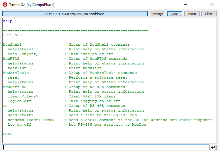
The demo application includes a command-line (shell) interface. Open one terminal to the USB CDC VCOM of the on-board debug interface. The ‘help’ command shows all available commands:
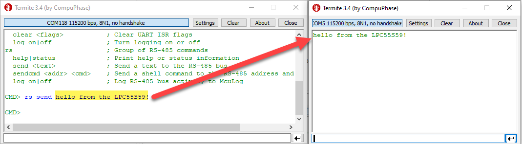
Open another terminal on the other side of the bus (in my case, the Sparkfun RS-485 converter). The Sparkfun converter is used to send and receive data on the bus.
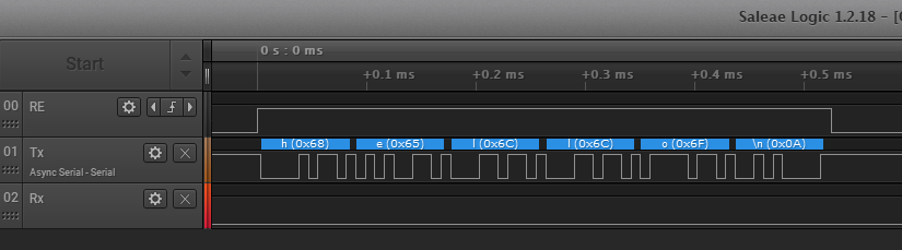
To send text from the LPC55S69, use the ‘rs send’ command, and it should show up on the other (Sparkfun) side:
Text send from to the LPC55S69 is shown in the console:
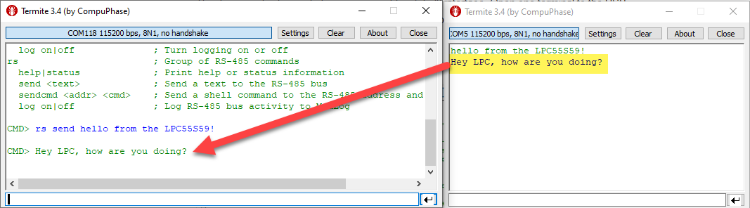
With this, we know that the communication is working.
Summary
It should not be hard to use the RS-485 bus and Modbus protocol with LPC55S69: In the software an UART needs to be configured to control the RTS line to drive transceiver RE/DE, an on the hardware side I need a transceiver which is used for the differential signal. I’m using the RS-485 successfully in many projects.
I just have covered sending simple text over the bus, but of course there are more features available. For example with ‘rs sendcmd’ you can send commands to an address on the bus and execute them on the remote node, or one can use the Modbus protocol, see the Modbus folder inside the McuLib. Be free to check the source code and the comments in it to explore more features like this.
With this, I hope you find that article useful for your own RS-485 and Modbus applications.
Happy communicating 🙂
Links
- Project on GitHub: https://github.com/ErichStyger/mcuoneclipse/tree/master/Examples/MCUXpresso/LPC55S69-EVK/LPC55S69_RS-485
- NXP LPC55S69-EVK web site: https://www.nxp.com/part/LPC55S69-EVK
- Sparkfun Converter RS-485 board: https://www.sparkfun.com/products/9822
- First Steps with the LPC55S69-EVK (Dual-Core ARM Cortex-M33 with Trustzone)
- Controlling an EV Charger with Modbus RTU
- DIY Split-Flap Display
- McuLib: https://github.com/ErichStyger/McuOnEclipseLibrary/tree/master
