
This week I’m sharing my experience “getting started” with the OKdo E1 board. This board, featuring the NXP LPC55S69 150 MHz, dual Cortex M33 core microcontroller was a joy to use. OKdo have provided an online Getting Started guide, and I’ve field-tested this for you. My video tutorial recorded as I follow the guide is less than 7 minutes long… it may take you a little longer if you need to download MCUXpresso IDE or the lpcxpresso55s69 Software Development Kit (SDK) but I am confident that you will quickly have the board up-and-running.
I don’t plan to simply reproduce the steps provided by OKdo. You can read their Quick Start guide here and note that if you go directly to www.okdo.com, you’ll then need to go to Projects, and then View All to find it.

What I found is that the E1 hardware is designed as a subset of the LPC55S69-EVK. So the 3-colour RGB LED, the 4 switches, all of the I2C and SPI drivers, even the USB Full Speed Device examples work simply ‘out of the box’. E1 is a low cost board, and so there is no audio codec, uSD card socket and no populated expansion headers. But the base E1 board is enabled by the lpcxpresso55s69 SDK, and so, once you’ve downloaded this from MCUXpresso IDE (and remember that there is not a dedicated OKdo E1 SDK) then you can just reuse all of that existing software. Genius! I was using MCUXpresso IDE version 11.1.0 (not quite the latest 11.1.1) and lpcxpresso55s69 SDK version 2.7.1. Just note that if you are reading this in the future, then some of the features may have changed in subsequent SDK versions, and your experience may not be 100% the same.

So far I have tested the following drivers from SDK v2.7.1 on the E1 board:
- USB
- Switches Reset, ISP, WAKE/GPIO / USER
- LEDS (R, G, B)
- GPIO, PINT and GINT
- UART, Console, PRINTF()
- High-Speed SPI
- I2C
- PWM
- UTICK
- CTimer
- PowerQuad
- RTC.
… all without issues. But I am getting ahead of myself, because Getting Started is about blinking an LED (again).
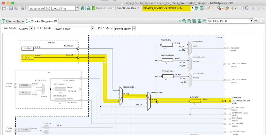
It is necessary to be aware of the missing 16 MHz crystal on the E1 board. But since there are two internal oscillators, and two PLLs inside the LPC55S69, we can run the board at 150 MHz using one of the internal references. I’ll show you the Clock Config tool and how to run the board at 150 MHz (using the internal FRO12M 12 MHz reference and the PLL0) next week. So for now, we just use the OKdo Getting Started material to configure the project to run from the FROHF96M 96 MHz internal reference:
So here it is: Getting Started tutorial with OKdo E1 board:
There are more videos about E1 board, Cortex M33 and LPC55S16 & LPC55S69 on the embeddedpro YouTube channel. Next week I’m going to provide a more full tutorial about the Clocks Config tool with OKdo E1 board. I hope to see you then.

I’m having some problems with my board. I think the jtag didn’t come programmed. When I connect the board through an USB cable to my computer (I tried with Linux and Windows 7) nothing happens.
LikeLiked by 1 person
Unfortunately I don’t own that board, so I cannot try it. Does anything enumerate on the USB bus if you plug it in? If no USB device shows up, then indeed the debug device on the board might not be programmed.
LikeLike
Hi Erich,
Problem solved. It was a problem with my USB cable. I tried another one and worked fine.
Now I want to learn how to use both cores on the microcontroller
LikeLike