“Note to myself: post articles about what students have done this semester…”
Students have turned in their semester project work. I have set for myself a goal to briefly describe to the ‘outside’ world what they did, as an inspirational source :-). So here is a first article about the project completed by Christoph Bühlmann who developed a shield for the FRDM-KL25Z board: a programmable ultrasonic shield:
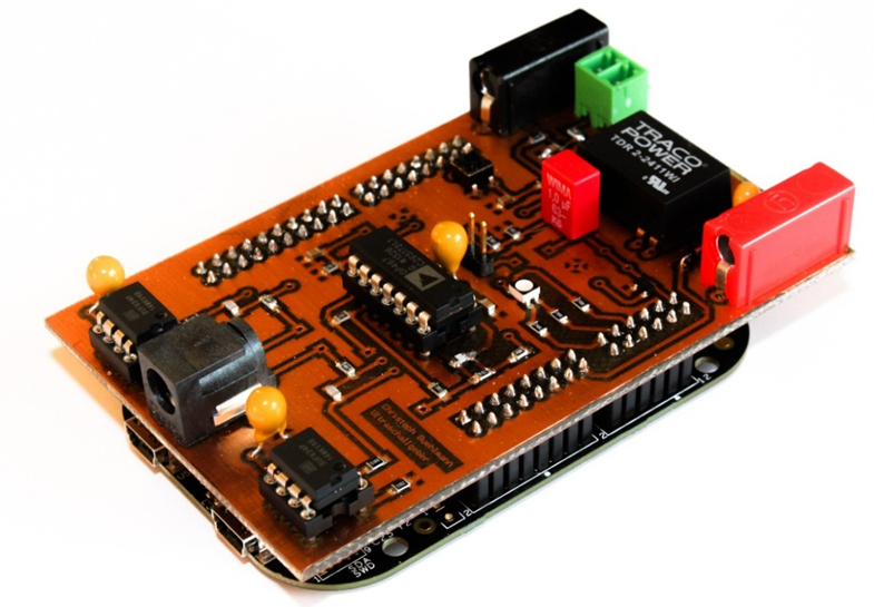
Ultrasonic Shield with Freescale FRDM-KL25Z (Source: Christoph Bühlmann)
The goal was to develop the hardware and software for the FRDM-KL25Z to produce an arbitrary ultrasonic signals which can be used for distance measurement or to do any other advanced usage of the signal. For this, it is important to directly drive the ultrasonic sound bursts. So unlikely with the HC-SR04 I’m using, this one allows custom ultrasonic signals to be sent out :-).
The requirements are:
- Continuous/periodic or ‘single shot’ ultrasonic burst generation based on 8bit values.
- Up to 100’000 values, stored on the device.
- 3 μs or less for a sending a single value.
- Battery or power supply operated
For the transducer the Prowave 400ST160 is used. Below is the overall block diagram:
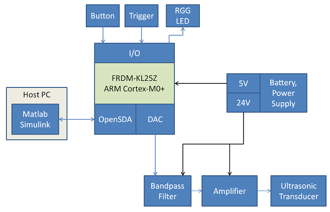
Block Diagram
- With Matlab/Simulink the waveform data is generated.
- The data gets transmitted to the FRDM-KL25Z board using the OpenSDA USB CDC (Serial over USB) connection, up to the maximum flash size of the KL25Z (up to 110 KByte data). The communication involves handshaking, and stores the values in FLASH.
- With a push button either manual or continues signal generation can be triggered.
- Additionally, there is an extra trigger signal so multiple boards can be triggered the same time.
- An RGB LED is used as visual indicator.
- Either a battery or a normal bench power supply can be used to generate the 5V for the FRDM board and the 24V for the amplifier.
- The FRDM board generates the signal with its onchip DAC, goes through a bandpass filter and amplifier to the external ultrasonic transducer.
The board has flexible power supply options: either battery operated or with a normal power supply. The booster logic can be attached to the shield:
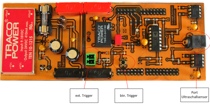
Top View Hardware (Source: Christoph Bühlmann)
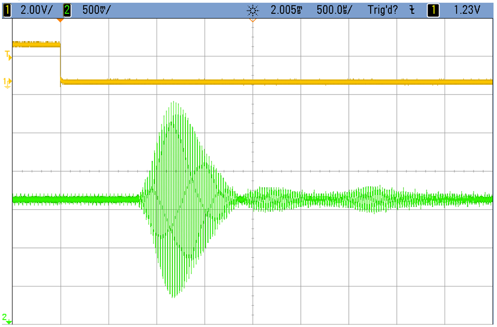
With an external trigger or push button a signal sequence can be started. Below shows the signal generated (orange) after the trigger event (green):
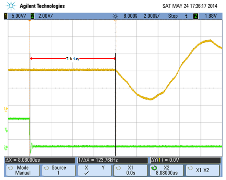
Signal after trigger
With a Simulink model the values are generated:
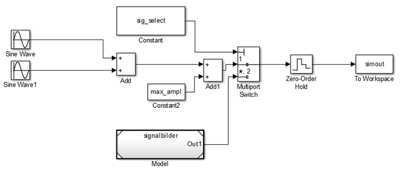
Simulink Model
Then with a GUI in Matlab the signal properties can be configured:
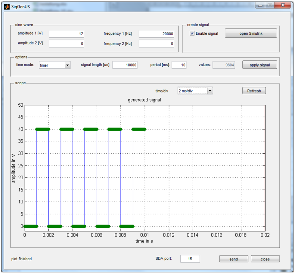
Matlab GUI (Source: Christoph Bühlmann)
From the GUI, the signal then gets transmitted to the FRDM-KL25Z board to generate the signal:
Generated signal (Source: Christoph Bühlmann)
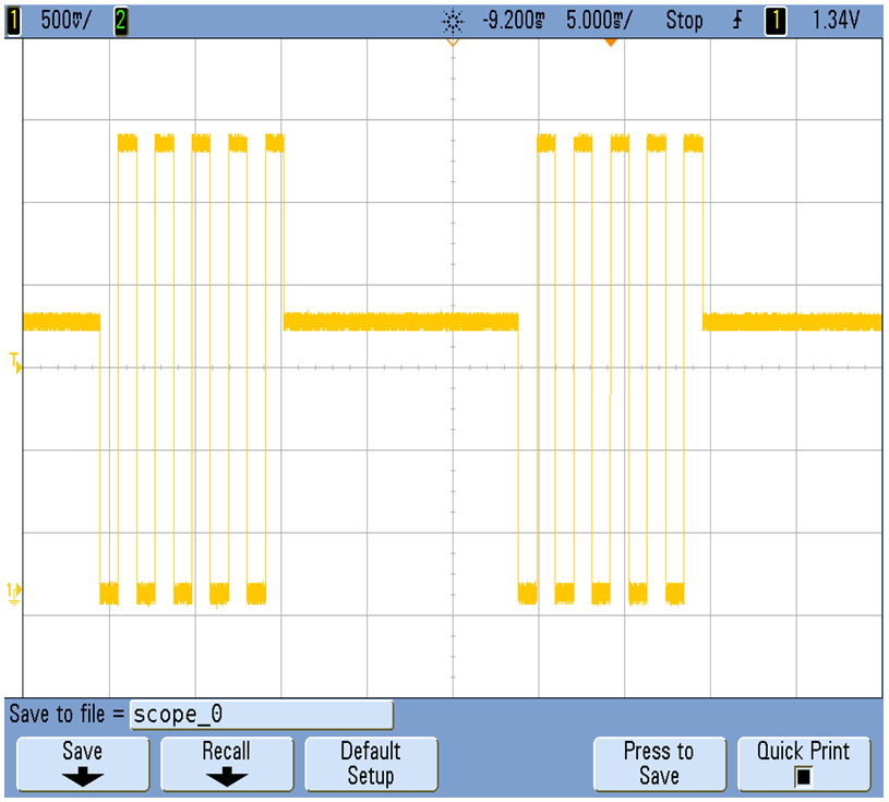
And with this, it is possible to generate custom bursts for distance measurement like the one below :-):
Ultrasonic Burst Signal (Source: Christoph Bühlmann)
Summary
The proof-of-concept works well so far, and custom waveforms can be generated, and the requirements have been met :-). A future extension would be to use DMA for the DAC to improve performance, as this is done now in a main loop. And to build up a network of sensors to build a localization network :-).
Many thanks to Christoph for his work and the material provided for this article!
Happy Transducing 🙂
